I strapped a Raspberry Pi Pico W to my garage door motor and now I can control my garage door from my phone! The Pico W hosts a simple webpage on my local network with three control buttons - one for Up, Stop and Down. Pressing one of the buttons does exactly what you'd expect.
This project writeup will walkthrough the control strategy, electronics, and code required to follow along. If you've never played around with smart-home, MicroPython or WiFi projects before, this project will get you started with all three!

Why do this project? Cause it's super cool! ...and garage door remotes suck. They're a whole extra thing you have to carry in your car or pocket; They take funny batteries and have buttons that wear out or become unresponsive. It's [today-year] and I rely entirely on my phone / biometrics for so many things... why not access control too?
Physical Interface
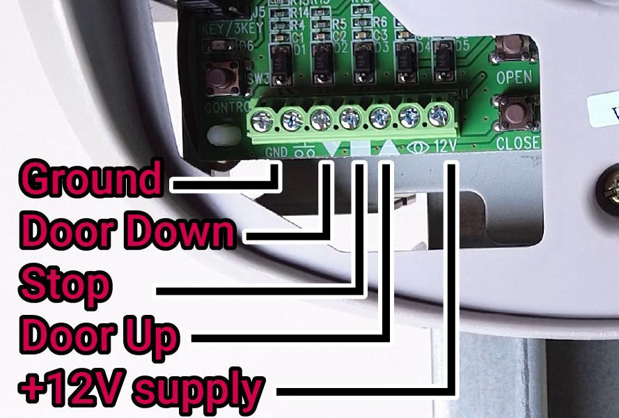
My model of garage door motor has an accessory terminal – there’s a connection for Up, Stop and Down. I expect these are meant to be hard-wired to some button panel that would mount to the wall. I measured the three control terminals and found they were at +12V. A bit of intuition told me that if I pull these to Ground, they would trigger the corresponding action. I bridged the UP terminal to Ground with a piece of wire and the door started raising - result! Note: it's generally a really bad idea to just bridge connections willy-nilly.
This control scheme is called "active-low" and it's very simple to create a circuit to interface a microcontroller (Pico W) with an active-low 12V input (garage door motor)
The following circuit uses a transistor (N-Channel MOSFET) to interface with the door-motor. When the Pico's GPIO is HIGH, the transistor will switch on, pulling the control channel to Ground. When the GPIO is LOW, the transistor is off.
This is the schematic for just one channel - to put it into practice we need three channels (Up, Stop, Down). 12VDC power is also provided by the door-motor, so we'll include a DC-DC converter to power the Pico W.
Bill of Materials
The following is all the hardware used to build the project.
- 1x Raspberry Pi Pico W
- 1x Makerverse Protoboard. I used a Pico Breakout
- 3x 2N7000 transistors (or similar logic-level N-ch MOSFET)
- 3x 10k Resistors
- 1x 5-pin terminal (2.54mm pitch)
- 1x 5V DC-DC Converter
- 2x 20pin Male header (could snap a 40-pin in half)
- 2x 20pin Female header (snapping a 40-pin always breaks one terminal. would need 2 in that case)
- 1x Schottky Diode (if you have a standard rectifier diode, that will work just fine too)
Other tools and consumables:
- light wire
- solder + soldering iron
- side cutters
- screwdriver for installation
Schematic
The following schematic shows how to assemble the components. The circuit is essentially a Pico W powered by a DC-DC converter. Three open-drain outputs interface with the door-motor inputs (not shown).

The 5-pin terminal (J1) supports all the connections to the door-motor. Power (12V, GND) comes in, with the 12V line passing through a DC-DC converter (U1). U1 has the VIN and ~SHTDN pins connected together as recommended by the manufacturer. 5V is output at U1-VOUT which flows through a Schottky diode (D1) and supplies the Pico (U2) at the VSYS pin. D1 ensures we can still connect to the Pico W via USB even while the Pico receives external power from U1. Q1-3 are the output drivers, which connect their respective control channels from J1 to ground - to trigger door-motor functions.
Build
The physical build was pretty straightforward and each step is shown in the project video. The Makerverse protoboard made assembly a breeze - the common rail for the open-drain outputs was very convenient, and making solder tracks between pads was really fast and simple. In all, it took about 2 hours to assemble the board which included filming.


Half of the protoboard is completely unused - if you're short on space you could easily snap this half off. Score along a row of holes with a sharp knife first to create a clean break.
MicroPython Code
For this project we'll work in MicroPython. The following code is for a simple static web server that hosts a page with three door-control buttons. A click or tap on one of the buttons triggers code that toggles the corresponding transistor - driving the door.
"""
Garage Door Controller code
Written by Michael Ruppe @ Core Electronics
    - Version 1.0 July 2022

Hosts a static webpage with three garage door control buttons (Up, Stop, Down)
Outputs: Open Drain channels to pull-down garage door controller channels.

Adapted from examples in: https://datasheets.raspberrypi.com/picow/connecting-to-the-internet-with-pico-w.pdf
"""

import time
import network
import uasyncio as asyncio
from machine import Pin

# Hardware definitions
led = Pin("LED", Pin.OUT, value=1)
pin_up = Pin(20, Pin.OUT, value=0)
pin_down = Pin(17, Pin.OUT, value=0)
pin_stop = Pin(18, Pin.OUT, value=0)

# Configure your WiFi SSID and password
ssid = 'My Network'
password = 'Password'

check_interval_sec = 0.25

wlan = network.WLAN(network.STA_IF)


# The following HTML defines the webpage that is served
html = """<!DOCTYPE html><html>
<head><meta name="viewport" content="width=device-width, initial-scale=1">
<link rel="icon" href="data:,">
<style>html { font-family: Helvetica; display: inline-block; margin: 0px auto; text-align: center;}
.button { background-color: #4CAF50; border: 2px solid #000000;; color: white; padding: 15px 32px; text-align: center; text-decoration: none; display: inline-block; font-size: 16px; margin: 4px 2px; cursor: pointer; }
.buttonRed { background-color: #d11d53; border: 2px solid #000000;; color: white; padding: 15px 32px; text-align: center; text-decoration: none; display: inline-block; font-size: 16px; margin: 4px 2px; cursor: pointer; }
text-decoration: none; font-size: 30px; margin: 2px; cursor: pointer;}
</style></head>
<body><center><h1>Garage Door Controller</h1></center><br><br>
<form><center>
<center> <button class="button" name="DOOR" value="UP" type="submit">Door UP</button>
<br><br>
<center> <button class="buttonRed" name="DOOR" value="STOP" type="submit">STOP</button>
<br><br>
<center> <button class="button" name="DOOR" value="DOWN" type="submit">Door DOWN</button></center>
</center></form>
<br><br>
<br><br>
<p>Last command issued was %s<p></body></html>
"""

def blink_led(frequency = 0.5, num_blinks = 3):
    for _ in range(num_blinks):
        led.on()
        time.sleep(frequency)
        led.off()
        time.sleep(frequency)

def control_door(cmd):
    if cmd == 'stop':
        pin_stop.on()
        blink_led(0.1, 1)
        pin_stop.off()

    if cmd == 'up':
        pin_up.on()
        blink_led(0.1, 1)
        pin_up.off()

    if cmd == 'down':
        pin_down.on()
        blink_led(0.1, 1)
        pin_down.off()


async def connect_to_wifi():
    wlan.active(True)
    wlan.config(pm = 0xa11140)  # Diable powersave mode
    wlan.connect(ssid, password)

    # Wait for connect or fail
    max_wait = 10
    while max_wait > 0:
        if wlan.status() < 0 or wlan.status() >= 3:
            break
        max_wait -= 1
        print('waiting for connection...')
        time.sleep(1)

    # Handle connection error
    if wlan.status() != 3:
        blink_led(0.1, 10)
        raise RuntimeError('WiFi connection failed')
    else:
        blink_led(0.5, 2)
        print('connected')
        status = wlan.ifconfig()
        print('ip = ' + status[0])


async def serve_client(reader, writer):
    print("Client connected")
    request_line = await reader.readline()
    print("Request:", request_line)
    # We are not interested in HTTP request headers, skip them
    while await reader.readline() != b"\r\n":
        pass

    # find() valid garage-door commands within the request
    request = str(request_line)
    cmd_up = request.find('DOOR=UP')
    cmd_down = request.find('DOOR=DOWN')
    cmd_stop = request.find('DOOR=STOP')
    print ('DOOR=UP => ' + str(cmd_up)) # show where the commands were found (-1 means not found)
    print ('DOOR=DOWN => ' + str(cmd_down))
    print ('DOOR=STOP => ' + str(cmd_stop))

    stateis = "" # Keeps track of the last command issued

    # Carry out a command if it is found (found at index: 8)
    if cmd_stop == 8:
        stateis = "Door: STOP"
        print(stateis)
        control_door('stop')

    elif cmd_up == 8:
        stateis = "Door: UP"
        print(stateis)
        control_door('up')

    elif cmd_down == 8:
        stateis = "Door: DOWN"
        print(stateis)
        control_door('down')

    response = html % stateis
    writer.write('HTTP/1.0 200 OK\r\nContent-type: text/html\r\n\r\n')
    writer.write(response)

    await writer.drain()
    await writer.wait_closed()


async def main():
    print('Connecting to WiFi...')
    asyncio.create_task(connect_to_wifi())

    print('Setting up webserver...')
    asyncio.create_task(asyncio.start_server(serve_client, "0.0.0.0", 80))

    while True:
        await asyncio.sleep(check_interval_sec)


try:
    asyncio.run(main())
finally:
    asyncio.new_event_loop()
Install
Installation is straightforward - the 5 terminals on the PCB correspond to 5 terminals on the door-motor's accessory terminals.

During this initial testing phase, I'll just place the cover back on the door-motor - leaving the PCB loose within. This is a temporary solution - though, as they say... nothing is more permanent than a temporary solution.

Things to consider before starting this project
There are a few risks with doing a project like this. Naturally you should weigh them and decide for yourself whether the reward is worth the risk. Some things to consider:
- Safety - Garage doors have their own force-sensitive safety thresholds so I consider this project decently safe: It relies on exiting mechanisms implemented by professional designers. A random trigger of the door may happen because of a firmware bug on the Pico, but I consider this no different to accidentally pressing the remote button
- Security - Time to address the elephant in the room - security (or lack thereof). Building a project like this means you're essentially allowing physical access to your house/garage to anybody that can connect to your WiFi network.
- Potential Damage to your Garage Door Motor - This is a pretty low-cost project! But the cost could explode if you happen to damage your garage door motor. Consider your personal knowledge, project skills and appetite for risk and proceed only if you have a lot of at least two of those.
Conclusion
The project works, and is really responsive! I'm thrilled with how good the user experience is. I'll need to lifetime test the project for several weeks to see if any long-term bugs arise eg. connection issues, timer overflow, python crashing etc.
As a cute additional feature, I'm routing all traffic for http://garage.door to the static IP address of my Pico W. I'm able to do this because I run my own local DNS server. It makes the URL way more memorable than a random IP address, and looks good as a bookmarklet on my phone's home-screen.

If you found this project helpful, have some questions, or want to see something in more detail then be sure to leave a comment below.
Happy Making!

