Pololu IR Beacon Transceiver Pair
Retired Product
Search for an alternative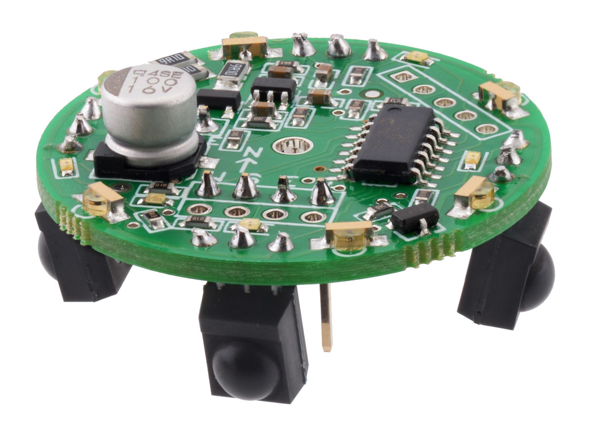 |
The Pololu IR beacons are small infrared transceivers meant to be used in pairs to give autonomous robots simple means for detecting each other. You can use the beacons to build pairs of robots that interact or chase one another, or to make a robot that can identify and return to a home base. For example, you could build a “cat robot” and “mouse robot” that each have an IR beacon, where the cat chases the mouse and the mouse runs away from the cat. The beacons are ideal for autonomous robot contests in which robots compete in pairs, such as MIT’s annual 6.270 autonomous robot design competition, where Pololu's original beacons were used for several years.
 |
These newer IR beacons feature round PCBs with six wide-angle emitters to provide uniform broadcasting in all directions. The operating voltage range has increased to 6 – 16 V, and on-board voltage monitoring enables a more consistent output brightness over the voltage range. Most components are pre-assembled, so all you need to solder is the connectors and sensors (make sure you solder them in from the bottom of the PCB!).
Note: The Pololu IR beacon is a kit; before using it, you need to assemble the beacon by soldering its components onto its circuit board. To use the kit in robotics projects, you need to connect it to your own robot controller. Please note that the IR beacons only work in pairs and that certain kinds of artificial lighting (e.g. some fluorescent lights) can interfere with the sensors.
Device Specifications
- PCB size: 1.35" diameter
- IR modulation frequency: 56 kHz
- Output refresh rate 20 Hz
- Detection range: 6 inches to ~15 feet (typical; actual max range will depend on ambient lighting conditions)
- Supply voltage: 6-16 V
- Data voltage: 5 V
- Number of IR detectors: 4
How the IR Beacons Work
(The following animations show the old IR beacon, but the operating principle is the same in these newer, round units.)
The beacons work by transmitting and detecting infrared light, much like a television remote control. Each beacon has six IR emitters and four IR detectors. The beacons alternate between transmitting and receiving so that they never get confused by reflections of their own transmissions.
 |
The transmit and detect cycle is carried out more than one thousand times per second, and a small microcontroller monitors all four detectors to decide the direction to the other beacon. The beacons have four red LEDs that indicate the direction to the other beacon; if you take two beacons and rotate them, the LEDs will always keep lighting up in the direction of the other beacon.
 |
Interfacing to the beacon is simple — it has four digital outputs that indicate which of its four sides detects the other beacon the strongest. You can establish the direction to another beacon to within a few degrees by rotating the beacon back and forth and noting the point where the output switches from one side to another. An enable input lets you select between active mode and a low-power mode.
IR Beacon Development Kit (Transmit-Only Beacon)
In response to customer requests, the IR beacon is available as just an assembled PCB with no IR sensors or firmware. This item is intended for advanced users who want to customize their IR beacon functionality by writing their own firmware. The main processor is a Microchip PIC16F630, and the PCB includes a footprint for a 5-pin header compatible with the PIC kit 2 programmer. The IR receiver modules are available separately. The schematic is shown below and is the only documentation shipped with this IR Beacon Development kit:
 |
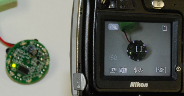
It is important to note that the IR beacon achieves its brightness by pulsing the IR LEDs with very high currents; turning on the IR LEDs continuously will burn them out. When testing the IR beacon, a digital camera can be useful in determining whether the IR LEDs are on. However, some cameras (usually more expensive ones) have better filters that block IR. In the picture below, a point-and-shoot camera shows the IR LEDs shining (in purple) but the DSLR with which the picture is taken does not show the LEDs.
 |
People often buy this product together with:
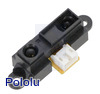 | Sharp GP2Y0A21YK0F Analog Distance Sensor 10-80cm |
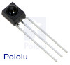 | Vishay TSOP34156 IR Receiver Module, 56kHz |
Dimensions
| Size: | 1.35" diameter |
|---|---|
| Weight: | 11.8 g |
General specifications
| Maximum range: | 15 ft1 |
|---|---|
| Minimum range: | 6 in |
| Minimum operating voltage: | 6 V |
| Maximum operating voltage: | 16 V |
Notes:
File downloads
-
IR Beacon user’s guide (317k pdf)
-
Drill guide for Pololu IR Beacon Transceiver (25k dxf)
This DXF drawing shows the locations of all of the board’s holes.
Recommended links
-
YouTube Video of IR Beacon Pair
This is a customer-produced YouTube video of a pair of Pololu IR Beacons in action.
Exact shipping can be calculated on the view cart page (no login required).
Products that weigh more than 0.5 KG may cost more than what's shown (for example, test equipment, machines, >500mL liquids, etc).
We deliver Australia-wide with these options (depends on the final destination - you can get a quote on the view cart page):
- $3+ for Stamped Mail (typically 10+ business days, not tracked, only available on selected small items)
- $7+ for Standard Post (typically 6+ business days, tracked)
- $11+ for Express Post (typically 2+ business days, tracked)
- Pickup - Free! Only available to customers who live in the Newcastle region (must order online and only pickup after we email to notify you the order is ready). Orders placed after 2PM may not be ready until the following business day.
Non-metro addresses in WA, NT, SA & TAS can take 2+ days in addition to the above information.
Some batteries (such as LiPo) can't be shipped by Air. During checkout, Express Post and International Methods will not be an option if you have that type of battery in your shopping cart.
International Orders - the following rates are for New Zealand and will vary for other countries:
- $12+ for Pack and Track (3+ days, tracked)
- $16+ for Express International (2-5 days, tracked)
If you order lots of gear, the postage amount will increase based on the weight of your order.
Our physical address (here's a PDF which includes other key business details):
40 Aruma Place
Cardiff
NSW, 2285
Australia
Take a look at our customer service page if you have other questions such as "do we do purchase orders" (yes!) or "are prices GST inclusive" (yes they are!). We're here to help - get in touch with us to talk shop.
Have a product question? We're here to help!
Guides

The Maker Revolution
Projects

The Rats Nest VCC Desktop Power Supply

Remote-Controlled Mars Rover

FlipperMate: Hands-Free Pinball

Makers love reviews as much as you do, please follow this link to review the products you have purchased.
Product Comments