
Pololu A4990 Dual Motor Driver Shield for Arduino
Retired Product
Search for an alternative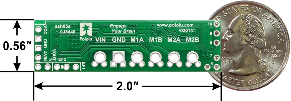 |
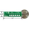
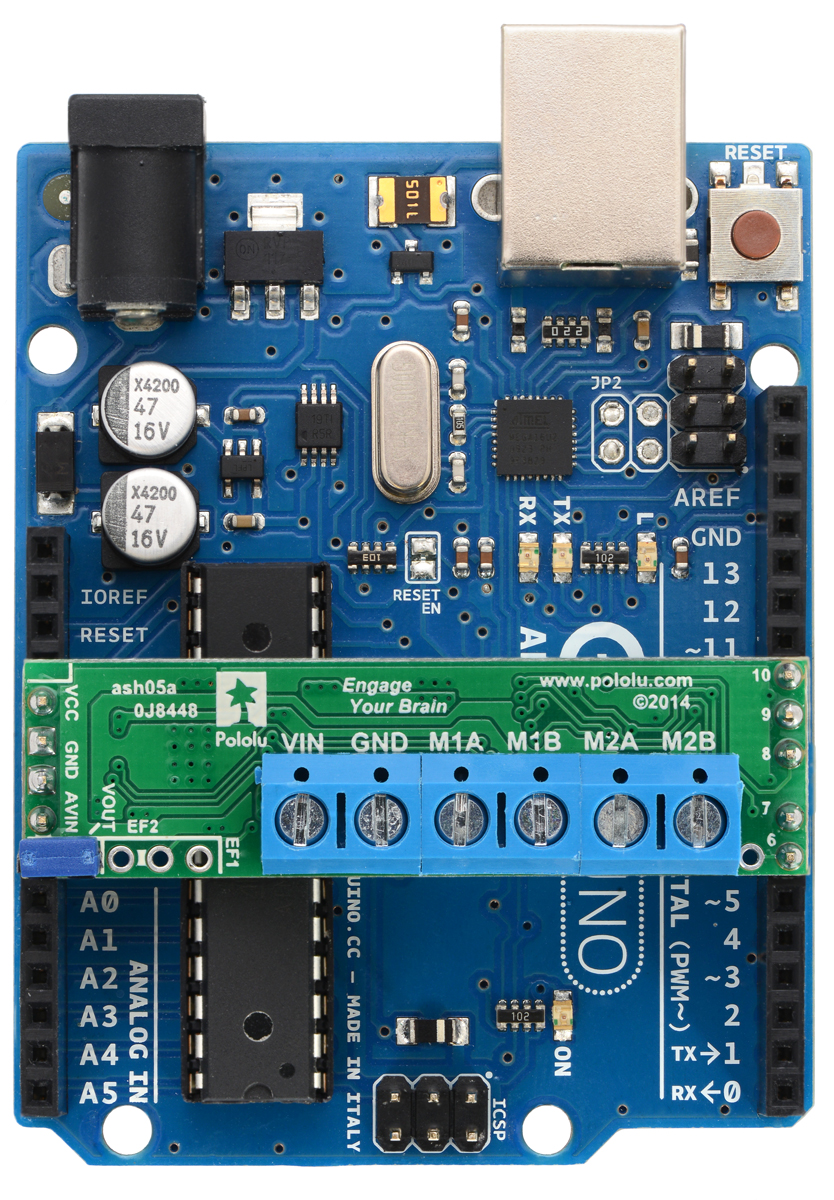
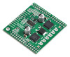
Pololu A4990 Dual Motor Driver Shield for Arduino, top view with dimensions. |
|---|
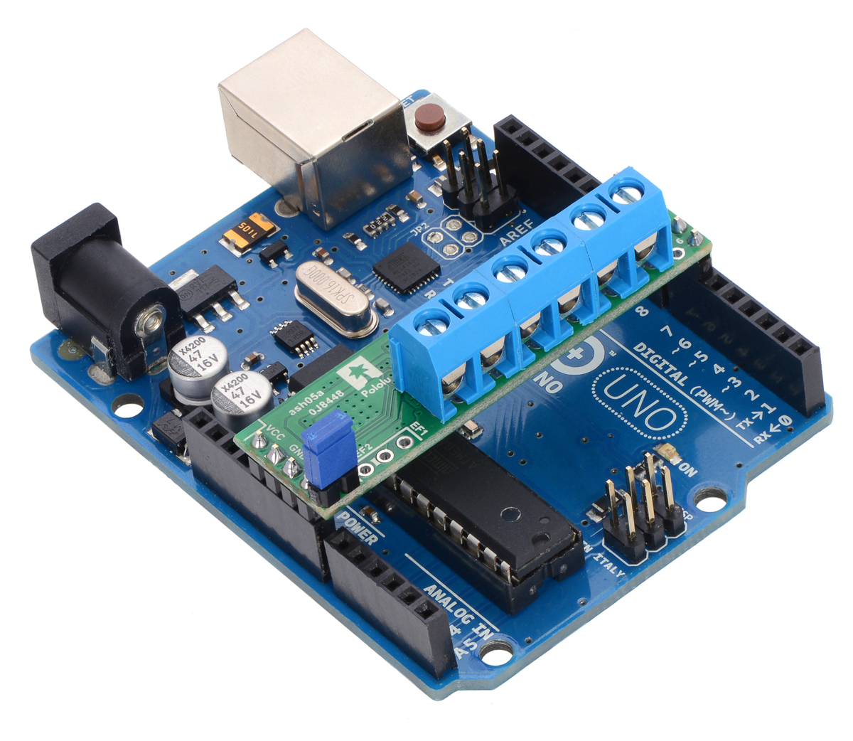
This motor driver shield and its corresponding Arduino library make it easy to control a pair of bidirectional, brushed DC motors with an Arduino or compatible board, such as the A-Star 32U4 Prime. The board features Allegro’s A4990 dual H-bridge motor driver IC, which operates from 6 V to 32 V. It can deliver a continuous 0.65 A to each motor channel, and the current control feature of the A4990 limits the peak motor current to about 0.9 A per channel with the onboard sense resistors, making this shield well suited for low-current, high-voltage motors.
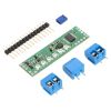
The shield ships fully populated with its SMD components, including the A4990 driver and a FET for reverse battery protection; header pins for interfacing with an Arduino and terminal blocks for connecting motors and power are included but are not soldered in (see the Assembly with included hardware section below).
|
|
The shield uses digital pins 6, 7, 8, 9, and 10 for its diagnostic and control lines. It should be compatible with any board that has a standard Arduino pin arrangement and the ability to generate PWM signals on pins 9 and 10. Compatible control boards include:
This shield is intended to provide a low-cost, basic motor driver option for Arduinos, so it is much smaller than typical Arduino shields and does not include pass-through, stackable headers. For higher-power drivers with more configuration options, see Pololu's larger MC33926 and VNH5019 motor driver shields.
For higher-current alternatives to this shield, please consider the dual MAX14870 motor driver shield or DRV8835 dual motor driver shield. Pololu also have a smaller A4990 carrier for those using something other than an Arduino or with tighter space constraints.
 |
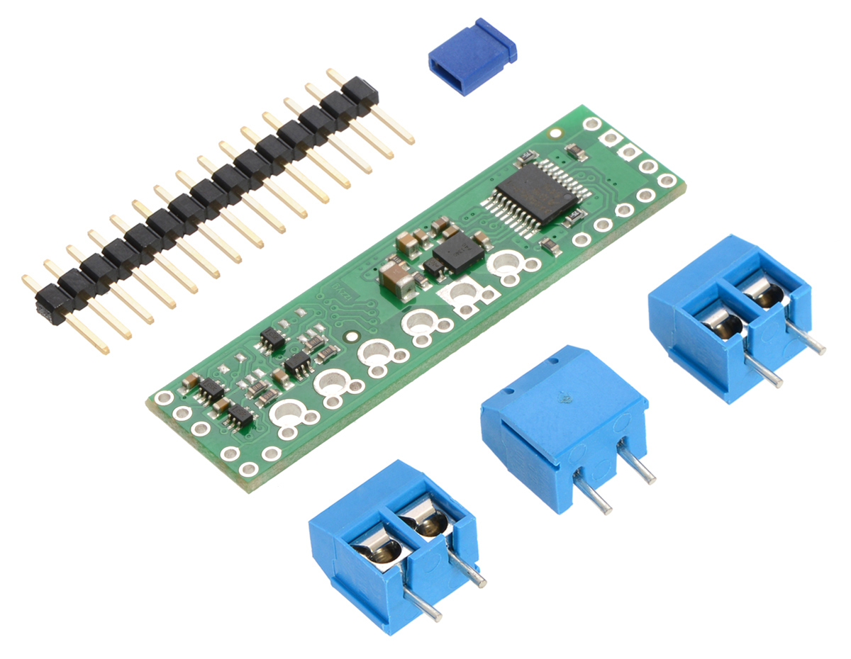
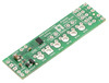
Pololu A4990 Dual Motor Driver Shield for Arduino, top and bottom sides. |
|---|
Features
- Dual-H-bridge motor driver: can drive two DC motors or one bipolar stepper motor
- Motor supply voltage: 6 V to 32 V
- Logic supply voltage 2.5 V to 5.5 V
- Output current: 0.65 A continuous per motor
- Current control limits peak current to 0.9 A per motor
- Can work with ultrasonic (> 20 kHz) PWM frequencies, which allows for quieter motor operation
- Shield can optionally power the Arduino base directly when motor supply voltage is suitable
- Arduino library makes it easy to get started using this board as a motor driver shield
- Robust:
- Reverse-voltage protection on the motor power supply
- Can survive input voltages up to 40 V
- Under-voltage and over-voltage protection
- Over-temperature protection
- Short-to-supply, short-to-ground, and shorted-load protection on the motor outputs
Assembly with included hardware
Before the shield can be plugged into your Arduino, header pins must be mounted to the bottom of the board (the side with all of the surface-mount components) by soldering them into the appropriate holes. The shield ships with a 15-pin 0.1" straight breakaway male header strip that can be broken into smaller pieces and used for this purpose. Four holes along the left side of the board (VCC, GND, GND, and AVIN) and all five holes along the right side of the board (digital pins 6 – 10) should be assembled with male header pins so that the shield will make the appropriate connections to the Arduino. Once assembled, one easy way to ensure that you are plugging the shield properly into the Arduino is to align the gap between pins 7 and 8 on the shield with the gap between pins 7 and 8 on the Arduino’s female headers.
|
|
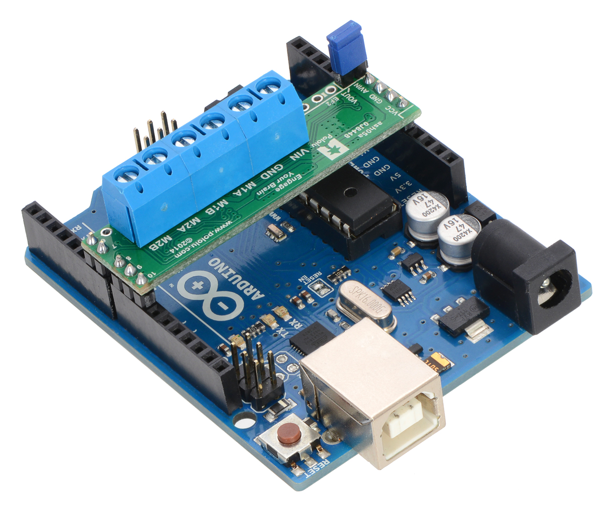
If you want the option of powering the Arduino from the shield, you can solder two male header pins to the lower-left corner of the board (in the silkscreen box labeled “VOUT”). These pins should point up, away from the Arduino. If you then place the included blue shorting block across these pins (as shown in the above assembled picture), reverse-protected shield power will power the Arduino through it’s VIN pin. See the Using the shield section below for more information on this, including some important warnings.
Three 2-pin, 5 mm terminal blocks are included for making easy motor and power connections to the shield once they have been slid together and soldered to the six large through-holes. Alternatively, you can solder 0.1" male header pins to the smaller through-holes above the terminal block holes, or you can just solder wires directly to the shield.
An Arduino is not included.
Using the shield
The shield plugs into Arduino digital pins 6, 7, 8, 9, and 10 on one side and Arduino VIN, GND, GND, and 5V/VCC on the other. The upper-left corner of the shield partially blocks the Arduino’s 3.3V pin, but this region of the board (marked with a white silkscreen box) can be removed if necessary to allow access.
In the shield’s default state, the motor driver shield and Arduino are powered separately, though they share a common ground and the Arduino’s 5V rail serves as the shield’s logic supply. When used this way, the Arduino must be powered via USB, its power jack, or its VIN pin, and the shield must be supplied with 6 V to 32 V through its large VIN and GND pads. Attempting to power the shield from the Arduino is not recommended as this could result in large currents flowing through small traces. However, if the motor power supply is suitable, it is possible to power the Arduino from the shield. This can be accomplished by placing a jumper between the shield pins in the lower-left corner labeled VOUT and AVIN, which connects the reverse-protected motor supply voltage to the Arduino’s VIN pin to power the Arduino. The Arduino’s power jack must remain disconnected at all times in this configuration.
Warning: When powering the Arduino from the motor shield, you must never connect a different power supply to the Arduino’s VIN pin or plug a power supply into the Arduino’s power jack, as doing so will create a short between the shield’s power supply and the Arduino’s power supply that could permanently damage both the Arduino and the motor shield. In this case, it is also important that your shield power supply is an acceptable voltage for your Arduino, so the full shield operating voltage range of 6 V to 32 V probably will not be available. For example, the recommended operating voltage of the Arduino Uno is 7 – 12 V.
The shield has integrated logic gates that simplify the control interface of the A4990 by reducing the number of PWM signals required. Each channel has a speed control input, MxPWM, and a direction control input, MxDIR. Arduino pins 9 and 7 are used to control the speed and direction, respectively, of motor 1, and pins 10 and 8 control the speed and direction of motor 2. The following truth table shows how the shield operates:
| MxDIR | MxPWM | MxA | MxB | operating mode |
|---|---|---|---|---|
| 0 | PWM | PWM | L | forward/brake at speed PWM % |
| 1 | PWM | L | PWM | reverse/brake at speed PWM % |
| X | 0 | L | L | brake low (outputs shorted to ground) |
The A4990 has two diagnostic pins, EF1 and EF2, that offer feedback about the state of the driver. These pins are open-drain outputs that are driven low by the chip to indicate faults (the datasheet describes what each combination of EF1 and EF2 means). Otherwise, these pins remain in a floating state. By default, EF2 is connected to Arduino digital pin 6 through a 1 kO protection resistor; with pin 6 configured as an input with its internal pull-up enabled, a low signal indicates an over-current, over-voltage, or over-temperature condition.
The EF1 and EF2 pins can more generally accessed via the 3-pin row of through-holes in the lower-left corner of the board. If you do not want to monitor the motor driver fault flags or would rather free up pin 6 for some other purpose, you can cut the trace that connects the EF2 pin to its neighboring (center) pin on the bottom side of the shield.
Current limiting
The A4990 can actively limit the current through the motors by using a fixed-frequency PWM current regulation (current chopping). This carrier board connects 0.075 O resistors to the current sense pins, which sets the current limit to a nominal 1 A per channel. In Pololu's tests, the board actually limited the motor current to slightly above 0.9 A.
Real-world power dissipation considerations
Even though the driver limits the motor current to about 0.9 A per channel, the chip by itself will overheat at lower currents. For example, in Pololu's tests at room temperature with no forced air flow, the chip was able to deliver 0.9 A per channel for approximately 15 seconds before the chip’s thermal protection kicked in. A continuous current of 0.65 A per channel was sustainable for many minutes without triggering a thermal shutdown. The actual current you can deliver will depend on how well you can keep the motor driver cool. Pololu's tests were conducted at 100% duty cycle; PWMing the inputs will introduce additional heating proportional to the frequency (unless the A4990 is already PWMing the outputs to limit the current).
This product can get hot enough to burn you long before the chip overheats. Take care when handling this product and other components connected to it.
Schematic diagram
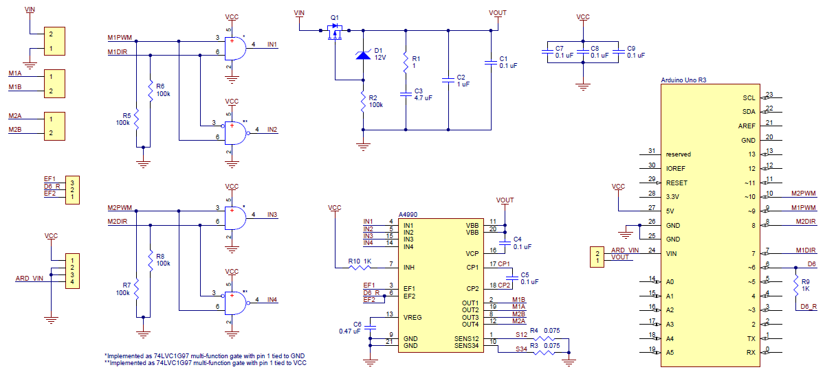 |
Pololu A4990 Dual Motor Driver Shield for Arduino schematic diagram. |
|---|
This schematic is also available as a downloadable pdf (268k PDF).
People often buy this product together with:
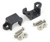 | Pololu Micro Metal Gearmotor Bracket Pair - Black |
 | Pololu Dual MC33926 Motor Driver Shield for Arduino |
 | Pololu DRV8835 Dual Motor Driver Shield for Arduino |
Dimensions
| Size: | 2.0" × 0.56"1 |
|---|---|
| Weight: | 2.5 g1 |
General specifications
| Motor driver: | A4990 |
|---|---|
| Motor channels: | 2 |
| Minimum operating voltage: | 6 V |
| Maximum operating voltage: | 32 V2 |
| Continuous output current per channel: | 0.65 A3 |
| Peak output current per channel: | 0.9 A4 |
| Reverse voltage protection?: | Y |
Identifying markings
| PCB dev codes: | ash05a |
|---|---|
| Other PCB markings: | 0J8448 |
Notes:
- 1
- Without included hardware.
- 2
- Over-voltage protection typically activates at 34 V, but it can trigger at voltages as low as 32 V.
- 3
- Typical results with 100% duty cycle at room temperature.
- 4
- Current is automatically limited to this by the driver; determined by onboard sense resistors.
File downloads
-
Pololu A49990 Dual Motor Driver Shield for Arduino schematic diagram (268k PDF)
Printable schematic diagram for the Pololu A4990 Dual Motor Driver Shield for Arduino.
-
A4990 datasheet (301k pdf)
Datasheet for the Allegro A4990 dual full bridge motor driver IC.
-
Dimension diagram of the Pololu A4990 Dual Motor Driver Shield for Arduino (236k pdf)
-
3D model of the Pololu A4990 Dual Motor Driver Shield for Arduino (6MB step)
-
Drill guide for the Pololu A4990 Dual Motor Driver Shield for Arduino (50k dxf)
This DXF drawing shows the locations of all of the board’s holes.
Recommended links
-
Arduino library for the Pololu A4990 Dual Motor Driver Shield
This library for the Arduino makes it easy to interface with Pololu’s A4990 Dual Motor Driver Shield and drive a pair of brushed DC motors. It has been explicitly tested with the Uno R3, Leonardo, Mega 2560 R3, Due, and Duemilanove (ATmega328P). A sample sketch is included with the library.
Exact shipping can be calculated on the view cart page (no login required).
Products that weigh more than 0.5 KG may cost more than what's shown (for example, test equipment, machines, >500mL liquids, etc).
We deliver Australia-wide with these options (depends on the final destination - you can get a quote on the view cart page):
- $3+ for Stamped Mail (typically 10+ business days, not tracked, only available on selected small items)
- $7+ for Standard Post (typically 6+ business days, tracked)
- $11+ for Express Post (typically 2+ business days, tracked)
- Pickup - Free! Only available to customers who live in the Newcastle region (must order online and only pickup after we email to notify you the order is ready). Orders placed after 2PM may not be ready until the following business day.
Non-metro addresses in WA, NT, SA & TAS can take 2+ days in addition to the above information.
Some batteries (such as LiPo) can't be shipped by Air. During checkout, Express Post and International Methods will not be an option if you have that type of battery in your shopping cart.
International Orders - the following rates are for New Zealand and will vary for other countries:
- $12+ for Pack and Track (3+ days, tracked)
- $16+ for Express International (2-5 days, tracked)
If you order lots of gear, the postage amount will increase based on the weight of your order.
Our physical address (here's a PDF which includes other key business details):
40 Aruma Place
Cardiff
NSW, 2285
Australia
Take a look at our customer service page if you have other questions such as "do we do purchase orders" (yes!) or "are prices GST inclusive" (yes they are!). We're here to help - get in touch with us to talk shop.
Have a product question? We're here to help!
Guides

The Maker Revolution
Projects

The Rats Nest VCC Desktop Power Supply

Remote-Controlled Mars Rover

FlipperMate: Hands-Free Pinball

Makers love reviews as much as you do, please follow this link to review the products you have purchased.
Product Comments