
Pololu 5V, 6A Step-Down Voltage Regulator D24V60F5
Retired Product
Replaced by: POLOLU-2866This product is no longer available. This page is only for reference.
 |

Overview
These high-current step-down (buck) regulators generate a fixed 5 V output from input voltages up to 38 V. They are switching regulators (also called switched-mode power supplies (SMPS) or DC-to-DC converters) and have a typical efficiency between 80% to 95%. The available output current is a function of the input voltage and efficiency (see the Typical Efficiency and Output Current section below), but the input current can typically be as high as 6 A.
A very similar version of this regulator is available with a typical maximum output current of 9 A. The two versions of the board are difficult to tell apart visually, so the bottom silkscreen includes a blank space where you can add your own distinguishing marks or labels. You should not use the colors of the printing on the tall, cylindrical electrolytic capacitors to differentiate the two versions as these colors are subject to change. Pololu also carry two much smaller versions of this regulator, one with a typical maximum output current of 2.5 A and one with a typical maximum output current of 5 A.
The ENABLE pin can be used to put the board in a low-power state that reduces the quiescent current to approximately 10 µA to 20 µA per volt on VIN, and a PG (power good) indicator makes it easy to monitor the state of the main power for your system. The regulator’s output voltage setting can also be lowered by adding an external resistor.
This regulator has built-in reverse-voltage protection, short-circuit protection, thermal shutdown (which typically activates at 160°C), a soft-start feature that reduces inrush current, and an under-voltage lockout that causes the regulator to turn off when the input voltage is below 4.2 V (typical).
 |
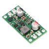
| Pololu 5V, 6A Step-Down Voltage Regulator D24V60F5, side view. |
|---|
Features
- Input voltage: 5 to 38 V (see below for more details on the regulator’s dropout voltage, which affects the low end of the operating range)
- Fixed 5 V output (with 4% accuracy); this can be lowered by adding an external resistor between FB and VOUT
- Typical maximum continuous output current: 6 A
- Integrated reverse-voltage protection, over-current protection, over-temperature shutoff, soft-start, and under-voltage lockout
- Typical efficiency of 80% to 95%, depending on input voltage and load; the switching frequency automatically changes at light loads to maintain high efficiencies
- 800 μA typical no-load quiescent current; can be reduced to 10 µA to 20 µA per volt on VIN by disabling the board
- “Power good” output indicates when the regulator cannot maintain its set output voltage
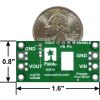
- Compact size: 1.6″ × 0.8″ × 0.3″ (40.6 × 20.3 × 7.6 mm)
- Four 0.086″ mounting holes for #2 or M2 screws
- Smaller holes for 0.1″ header pins and larger holes for terminal blocks offer several options for connecting to the board
Using the regulator
Connections
This boost regulator has six connections: input voltage (VIN), ground (GND), output voltage (VOUT), feedback (FB), ENABLE, and power good (PG).
 |
The input voltage, VIN, powers the regulator and can be supplied with voltages up to 38V. The effective lower limit of VIN is VOUT plus the regulator’s dropout voltage, which varies approximately linearly with the load from around 500 mV to a little over a volt (see below for a graph of the dropout voltage as a function of the load).
The output voltage, VOUT, is set to 5V by default. The output voltage can optionally be lowered by adding a resistor between the FB pin and VOUT as detailed in the Decreasing the output voltage section below.
The regulator is enabled by default: a 100 kΩ pull-up resistor on the board connects the ENABLE pin to reverse-protected VIN. The ENABLE pin can be driven low (under 0.6 V) to put the board into a low-power state. The quiescent current draw in this sleep mode is dominated by the current in the pull-up resistor from ENABLE to VIN and by the reverse-voltage protection circuit, which will draw between 10 µA and 20 µA per volt on VIN when ENABLE is held low. If you do not need this feature, you should leave the ENABLE pin disconnected.
The “power good” indicator, PG, is an open-drain output that goes low when the regulator’s output voltage falls below 90% of what it is set to (i.e. 4.5 V with the default 5 V output setting). An external pull-up resistor is required to use this pin.
|
|


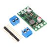
The connections are labeled on the back side of the PCB, and the board offers several options for making electrical connections. The eight smaller through-holes on the ends of the board are arranged with a 0.1″ spacing for compatibility with solderless breadboards, connectors, and other prototyping arrangements that use a 0.1″ grid; you can solder pieces of the included 12×1 straight male header strip into these smaller holes. Alternatively, you can solder the included 2-pin 5mm-pitch terminal blocks to the two pairs of larger holes on the ends of the board. For the most compact installation, you can solder wires directly to the board.
 |
| Pololu Step-Down Voltage Regulator D24V60F5 showing wires soldered directly to the board and passing through the mounting holes for strain relief. |
|---|
The board has four 0.086″ mounting holes intended for #2 or M2 screws. The mounting holes are in the four corners of the board and are separated by 1.4″ horizontally and 0.6″ vertically. In applications where mounting screws are not used and wires are soldered directly to the board, the insulated part of the wires can be passed through the mounting holes for strain relief. The picture above shows an example of this with 20 AWG wire, which was close to the limit of what would fit through the mounting holes.
Decreasing the output voltage
The set voltage can optionally be decreased by adding an external resistor between the FB and the neighboring VOUT pin. The equations below show how the output voltage relates to the value of an external resistor, R:
text (VOUT) = ((5.24 * R) /(16.2 text(kΩ) + R) + 1) * 0.8 text(V)
R = ((text(VOUT) – 0.8 text(V))/(5 text(V) – text (VOUT) ))*16.2 text(kΩ)
For example, to get an output voltage of 3.3 V, you could put a 23.7 kΩ resistor between FB and VOUT.
The minimum VOUT for this regulator is 0.8 V. Please note that the small VOUT pin next to FB is not intended to source much current; its purpose is to provide a convenient spot for connecting a voltage-adjustment resistor.
Typical efficiency and output current
The efficiency of a voltage regulator, defined as (Power out)/(Power in), is an important measure of its performance, especially when battery life or heat are concerns. As shown in the graph below, these switching regulators have an efficiency of 80% to 95% for most combinations of input voltage, and load.
 |
The maximum achievable output current of the board depends on many factors, including the ambient temperature, air flow, heat sinking, and the input and output voltage.
During normal operation, this product can get hot enough to burn you. Take care when handling this product or other components connected to it.
Typical dropout voltage
The dropout voltage of a step-down regulator is the minimum amount by which the input voltage must exceed the regulator’s target output voltage in order to ensure the target output can be achieved. For example, if a 5 V regulator has a 1 V dropout voltage, the input must be at least 6 V to ensure the output is the full 5 V. The following graph shows the dropout voltage for the D24V60F5 regulator as a function of the output current:
 |
Switching frequency and behavior under light loads
The regulator generally operates at a switching frequency of around 470 kHz, but the frequency drops when encountering a light load to improve efficiency. This could make it harder to filter out noise on the output caused by switching. This also causes small variations in the output voltage like those shown in the graph below:
 |
Exact shipping can be calculated on the view cart page (no login required).
Products that weigh more than 0.5 KG may cost more than what's shown (for example, test equipment, machines, >500mL liquids, etc).
We deliver Australia-wide with these options (depends on the final destination - you can get a quote on the view cart page):
- $3+ for Stamped Mail (typically 10+ business days, not tracked, only available on selected small items)
- $7+ for Standard Post (typically 6+ business days, tracked)
- $11+ for Express Post (typically 2+ business days, tracked)
- Pickup - Free! Only available to customers who live in the Newcastle region (must order online and only pickup after we email to notify you the order is ready). Orders placed after 2PM may not be ready until the following business day.
Non-metro addresses in WA, NT, SA & TAS can take 2+ days in addition to the above information.
Some batteries (such as LiPo) can't be shipped by Air. During checkout, Express Post and International Methods will not be an option if you have that type of battery in your shopping cart.
International Orders - the following rates are for New Zealand and will vary for other countries:
- $12+ for Pack and Track (3+ days, tracked)
- $16+ for Express International (2-5 days, tracked)
If you order lots of gear, the postage amount will increase based on the weight of your order.
Our physical address (here's a PDF which includes other key business details):
40 Aruma Place
Cardiff
NSW, 2285
Australia
Take a look at our customer service page if you have other questions such as "do we do purchase orders" (yes!) or "are prices GST inclusive" (yes they are!). We're here to help - get in touch with us to talk shop.
Have a product question? We're here to help!
Guides

The Maker Revolution
Projects
")
Raspberry Pi Cyberdeck (SDR Edition)

Pico-Dog Motion Activated Audio Alarm

WaveJumper: Music Sample Slicer on a Breadboard

Makers love reviews as much as you do, please follow this link to review the products you have purchased.
Product Comments