
Pololu 5-Channel Reflectance Sensor Array for Balboa 32U4 Balancing Robot
In stock, ships same business day if ordered before 2PM
Fastest delivery: Tomorrow*
Disclaimer:
For next-day delivery, the shipping address must
be in the AusPost next-day network, eParcel Express must be selected, and the order must be placed
before 2PM AEST Mon-Thurs excluding NSW Public Holidays. Orders may be delayed due to AusPost
pickup timings and order verifications. eParcel Express is typically a 1-day service within the
AusPost next-day network, though it is sometimes 2+ days.
Quantity Discounts:
- 10+ $10.21 (exc GST)
- 25+ $9.89 (exc GST)
 |
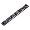
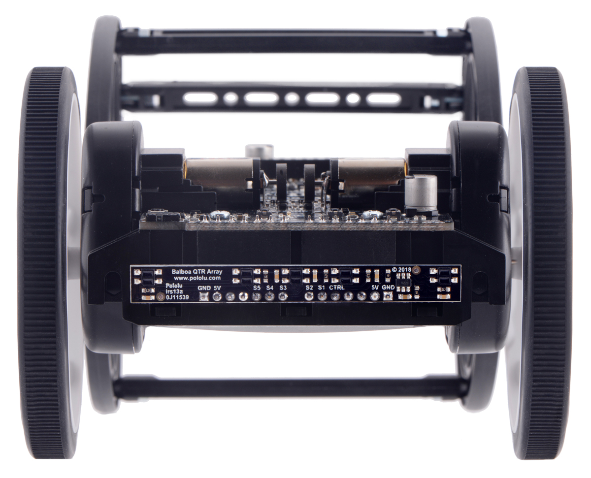
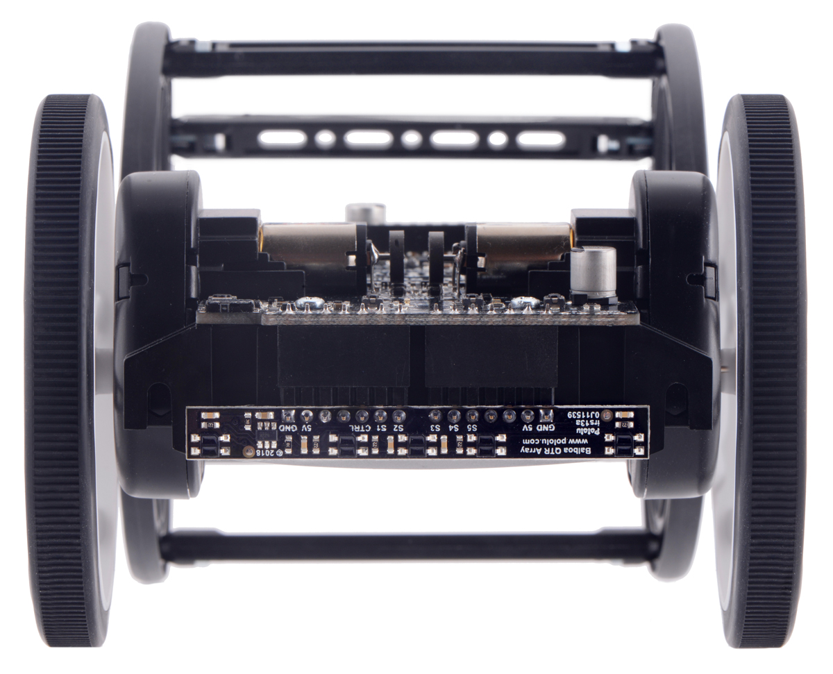
The 5-Channel Reflectance Sensor Array for Balboa provides an easy way to add line sensing to the Balboa 32U4 Balancing Robot. It features five separate reflectance sensors, each consisting of a dimmable IR emitter coupled with a phototransistor that responds based on how much emitter light is reflected back to it. The array is intended for Balboas assembled with 80×10mm wheels that are operating in upright (balancing) orientations.
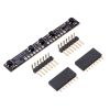
Included components and mounting options
The reflectance sensor array ships with all of the components you need to connect it to a Balboa 32U4 control board:
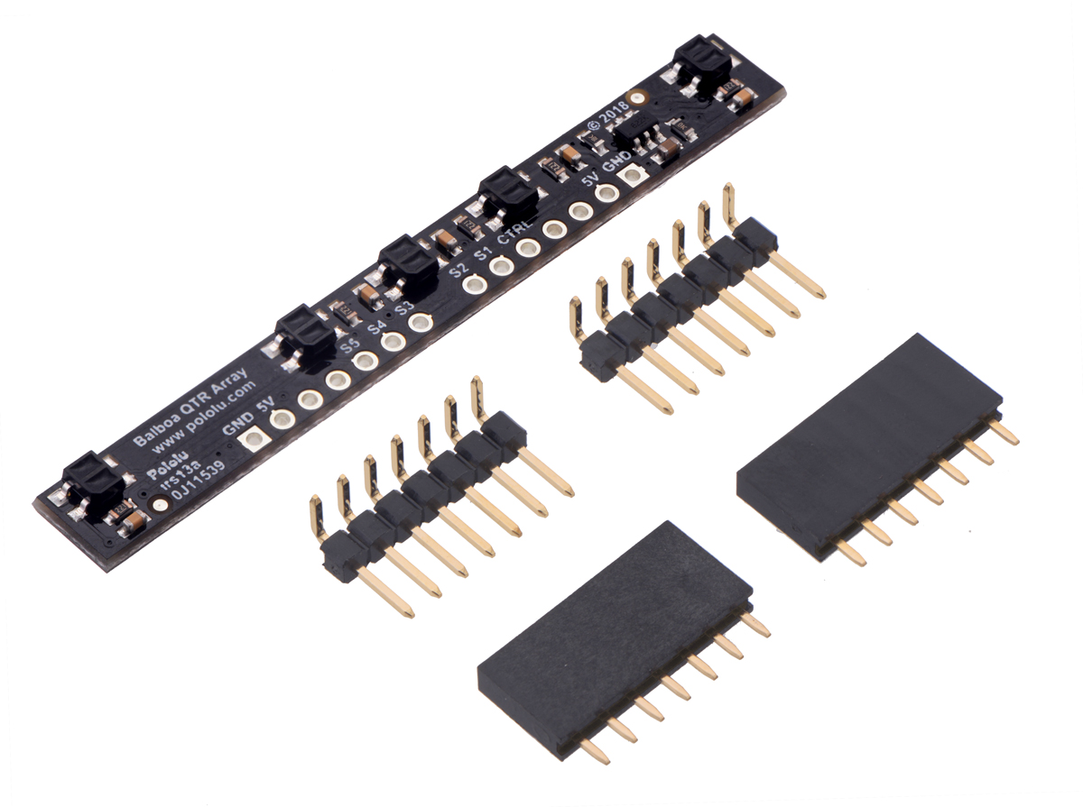 |
The 1×7 female headers should be soldered to the connections near the bottom edge of the control board. You can do this without removing your Balboa control board from the chassis. One female header should be soldered between the pins labeled GND and A3, and the other female header should be soldered between the pins labeled GND and A2. The solder joints should be on the component side of the control board.
|
|
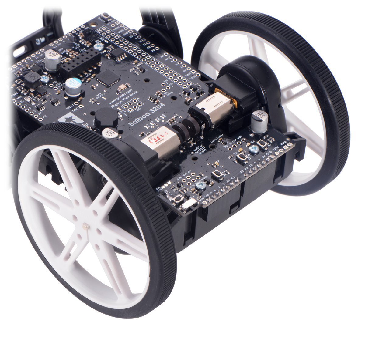
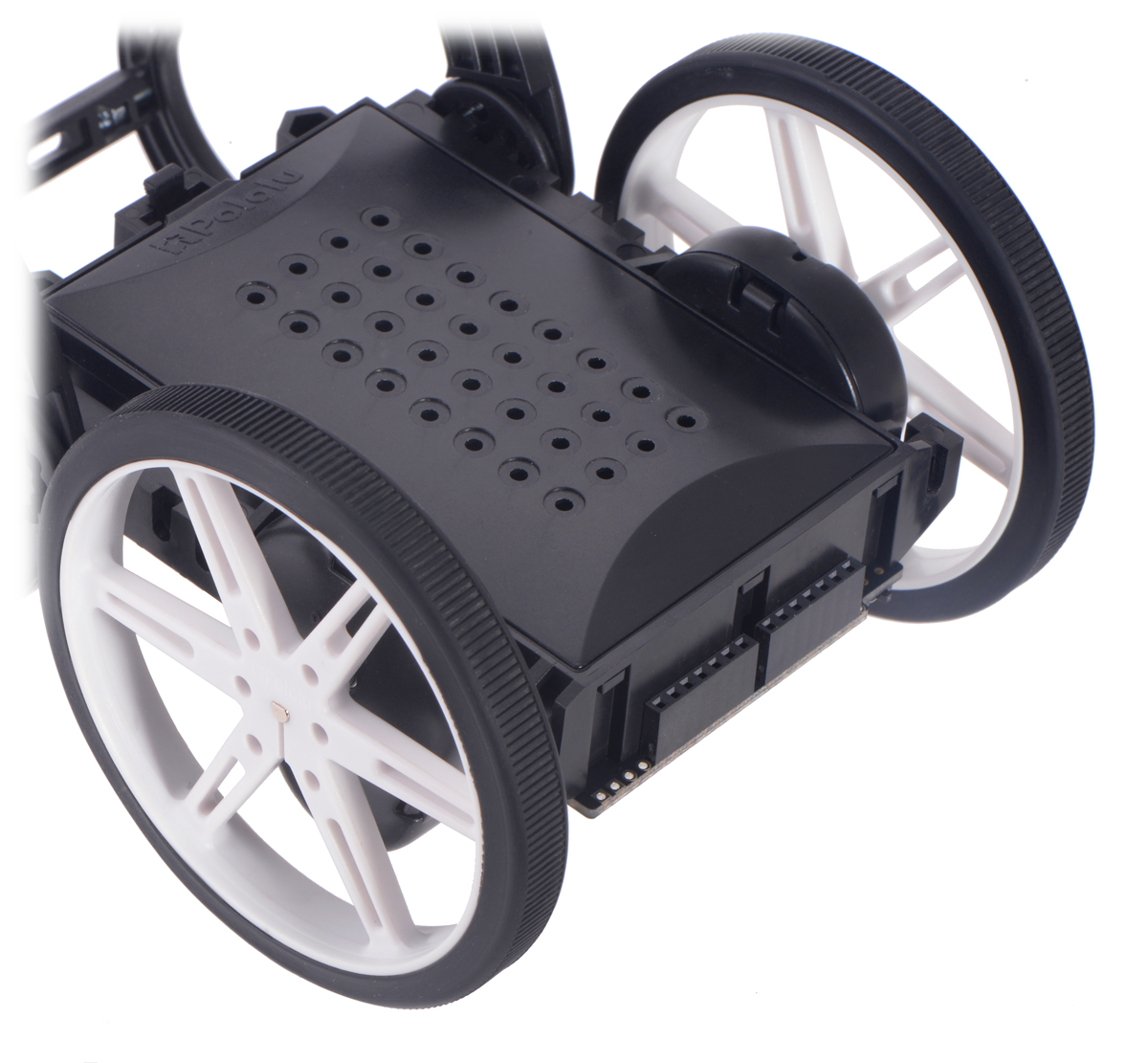
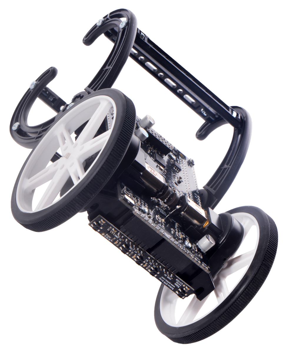
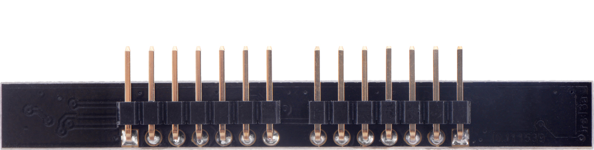
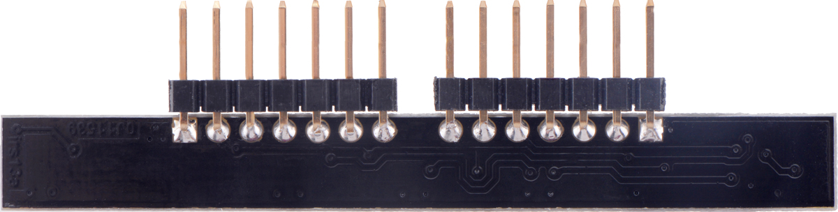
The sensor board can be mounted to the Balboa so that it aligns with the center axis of the chassis or the edge of the chassis, which might make following a line easier (since the sensors will be farther forward when the Balboa is upright). How the included right angle headers are connected to the sensor board determines whether the board will be center- or edge-aligned. See the pictures below for how to position the header pins for each mounting option.
|
|
|
|
Using the sensor array
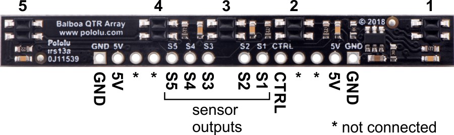
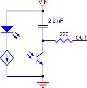 |
Schematic diagram of an individual QTR sensor channel on an RC-type board. This applies only to the newer QTRs with dimmable emitters. |
|---|
The array uses the same sensor modules as Pololu's QTR reflectance sensors and has the same principle of operation as the RC versions, for example, the QTR-MD-05RC. The typical sequence for reading a sensor is:
- Turn on IR LEDs (optional).
- Set the I/O line to an output and drive it high.
- Allow at least 10 µs for the sensor output to rise.
- Make the I/O line an input (high impedance).
- Measure the time for the voltage to decay by waiting for the I/O line to go low.
- Turn off IR LEDs (optional).
These steps can typically be executed in parallel on multiple I/O lines. Because this array works like Pololu's other QTR sensor boards, you can use it with Pololu's QTR Arduino library, which provides methods for controlling the emitters, calibrating the module, and reading the individual sensor values. Keep in mind that how you mount your sensor will determine which I/O lines on the Balboa you are connected to. You can read the silkscreen markings on the sensor board and the Balboa to determine which sensor is connected to which I/O line.
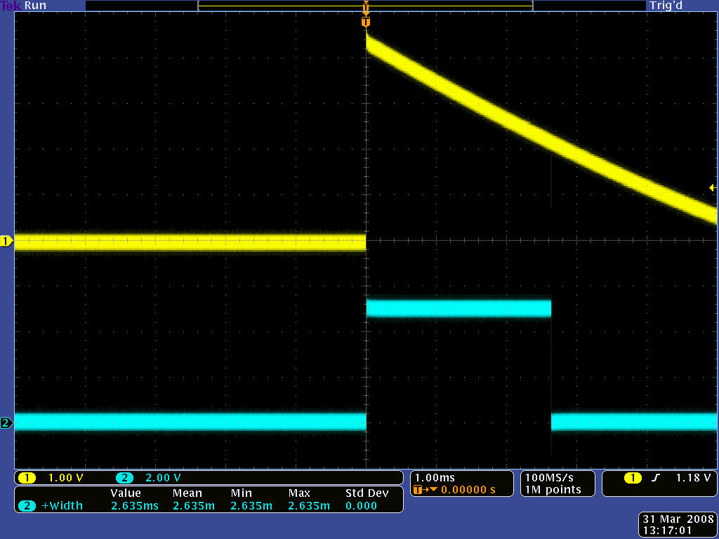
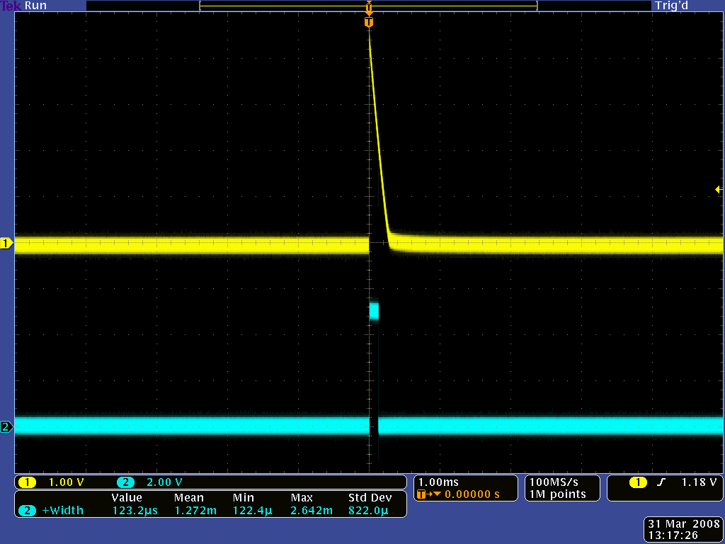
 |
With a strong reflectance, the decay time can be as low as a few microseconds; with no reflectance, the decay time can be up to a few milliseconds. Meaningful results can be available within 1 ms in typical cases (i.e. when not trying to measure subtle differences in low-reflectance scenarios), allowing up to 1 kHz sampling of all sensors. If lower-frequency sampling is sufficient, you can achieve substantial power savings by turning off the LEDs. For example, if a 100 Hz sampling rate is acceptable, the LEDs can be off 90% of the time, lowering average current consumption from 125 mA to 13 mA.
|
|
Emitter control
 |
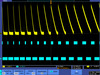
Demo of IR LED dimming on the 5-Channel Sensor Array for Balboa 32U4 (as seen through an old digital camera that can see IR). |
|---|
The sensor array maintains a constant current through its IR emitters, keeping the emitters’ brightness constant. The emitters can be controlled with the board’s CTRL pin.
Driving the CTRL pin low for at least 1 ms turns off the emitter LEDs, while driving it high (or allowing the board to pull it high) turns on the emitters with the board’s default (full) current, which is 20 mA. For more advanced use, the CTRL pin can be pulsed low to cycle the associated emitters through 32 dimming levels.
To send a pulse, drive the CTRL pin low for at least 0.5 µs (but no more than 300 µs), then high for at least 0.5 µs; (it should remain high after the last pulse). Each pulse causes the driver to advance to the next dimming level, wrapping around to 100% after the lowest-current level. Each dimming level corresponds to a 3.33% reduction in current, except for the last three levels, which represent a 1.67% reduction, as shown in the table below. Note that turning the LEDs off with a >1 ms pulse and then back on resets them to full current.
| Dimming level (pulses) | Emitter current (%) | Dimming level (pulses) | Emitter current (%) | |
|---|---|---|---|---|
| 0 | 100.00% | 16 | 46.67% | |
| 1 | 96.67% | 17 | 43.33% | |
| 2 | 93.33% | 18 | 40.00% | |
| 3 | 90.00% | 19 | 36.67% | |
| 4 | 86.67% | 20 | 33.33% | |
| 5 | 83.33% | 21 | 30.00% | |
| 6 | 80.00% | 22 | 26.67% | |
| 7 | 76.67% | 23 | 23.33% | |
| 8 | 73.33% | 24 | 20.00% | |
| 9 | 70.00% | 25 | 16.67% | |
| 10 | 66.67% | 26 | 13.33% | |
| 11 | 63.33% | 27 | 10.00% | |
| 12 | 60.00% | 28 | 6.67% | |
| 13 | 56.67% | 29 | 5.00% | |
| 14 | 53.33% | 30 | 3.33% | |
| 15 | 50.00% | 31 | 1.67% |
For example, to reduce the emitter current to 50%, apply 15 low pulses to the CTRL pin and then keep it high after the last pulse.
Example code
The Balboa32U4 Arduino Library provides a way to easily read sensor values from the reflectance sensor array, and it includes a demo sketch showing how to do so. See this section of the Balboa 32U4 user’s guide for library installation instructions and the library documentation for more information.
People often buy this product together with:
 | Pololu Wheel 80×10mm Pair - Red |
 | Pololu Wheel 80×10mm Pair - Blue |
 | 50:1 Micro Metal Gearmotor HPCB 6V with Extended Motor Shaft |
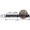
Dimensions
| Size: | 2.52" × 0.29" |
|---|---|
| Weight: | 1.8 g1 |
General specifications
| Voltage: | 5 V2 |
|---|---|
| Peak wavelength: | 940 nm |
| Maximum current draw: | 40 mA3 |
Identifying markings
| PCB dev codes: | irs13a |
|---|---|
| Other PCB markings: | 0J11539 |
Notes:
- 1
- Without included headers.
- 2
- Module is intended to be powered by the Balboa's 5V line.
- 3
- With all LEDs on at max brightness setting.
Documentation and other information
-

Pololu QTR Reflectance Sensor Application Note (Printable PDF)
Information about using the Pololu QTR reflectance sensors, including differences between A-type and RC-type sensors and sample oscilloscope screen captures of sensor outputs.
File downloads
-
Schematic diagram of the 5-Channel Reflectance Sensor Array for Balboa 32U4 Balancing Robot (87k pdf)
-
Dimension diagram of the 5-Channel Reflectance Sensor Array for Balboa 32U4 Balancing Robot (153k pdf)
-
3D model of the 5-Channel Reflectance Sensor Array for Balboa 32U4 Balancing Robot (8MB step)
-
Drill guide for the 5-Channel Reflectance Sensor Array for Balboa 32U4 Balancing Robot (30k dxf)
This DXF drawing shows the locations of all of the board’s holes.
Recommended links
-
The Balboa32U4 library for the Arduino IDE helps interface with the on-board hardware on the Balboa 32U4 control board as well as the optional 5-channel reflectance sensor array for the Balboa.
-
Arduino library for the Pololu QTR Reflectance Sensors
This library for Arduino makes it easy to interface with Pololu QTR Reflectance Sensors.
Exact shipping can be calculated on the view cart page (no login required).
Products that weigh more than 0.5 KG may cost more than what's shown (for example, test equipment, machines, >500mL liquids, etc).
We deliver Australia-wide with these options (depends on the final destination - you can get a quote on the view cart page):
- $3+ for Stamped Mail (typically 10+ business days, not tracked, only available on selected small items)
- $7+ for Standard Post (typically 6+ business days, tracked)
- $11+ for Express Post (typically 2+ business days, tracked)
- Pickup - Free! Only available to customers who live in the Newcastle region (must order online and only pickup after we email to notify you the order is ready). Orders placed after 2PM may not be ready until the following business day.
Non-metro addresses in WA, NT, SA & TAS can take 2+ days in addition to the above information.
Some batteries (such as LiPo) can't be shipped by Air. During checkout, Express Post and International Methods will not be an option if you have that type of battery in your shopping cart.
International Orders - the following rates are for New Zealand and will vary for other countries:
- $12+ for Pack and Track (3+ days, tracked)
- $16+ for Express International (2-5 days, tracked)
If you order lots of gear, the postage amount will increase based on the weight of your order.
Our physical address (here's a PDF which includes other key business details):
40 Aruma Place
Cardiff
NSW, 2285
Australia
Take a look at our customer service page if you have other questions such as "do we do purchase orders" (yes!) or "are prices GST inclusive" (yes they are!). We're here to help - get in touch with us to talk shop.
Have a product question? We're here to help!
- Solderless Breadboard - 830 Tie Points (ZY-201)SKU: CE05314 Brand: Core ElectronicsSolid construction with handy binding posts.
- 22pF Ceramic Disc CapacitorSKU: CE05189 Brand: Core Electronics50V Voltage Rating, 5% Tolerance. Single pitch lead spacing.
-
-


Videos
View AllGuides

The Maker Revolution

Getting Hands-on with Sensors
Projects

WhyzaGC - Feather ESP32 addon to the MightyOhm Gieger Counter

Makers love reviews as much as you do, please follow this link to review the products you have purchased.
Product Comments