
Pololu 3.3V Step-Up Voltage Regulator NCP1402
Retired Product
Search for an alternativeDiscontinuation notice: The NCP1402 IC used by this voltage regulator has been discontinued by the manufacturer. Pololu strongly recommend Pololu's newer 5V U1V10F5 and 3.3V U1V10F3 boost regulators as alternatives. The U1V10Fx voltage regulators are smaller, more efficient, have a lower minimum operating voltage, and can deliver significantly more current than the NCP1402-based regulators. These newer regulators also automatically switch into linear down-regulation mode when the input voltage exceeds the output.
 |
 |
 |
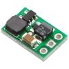
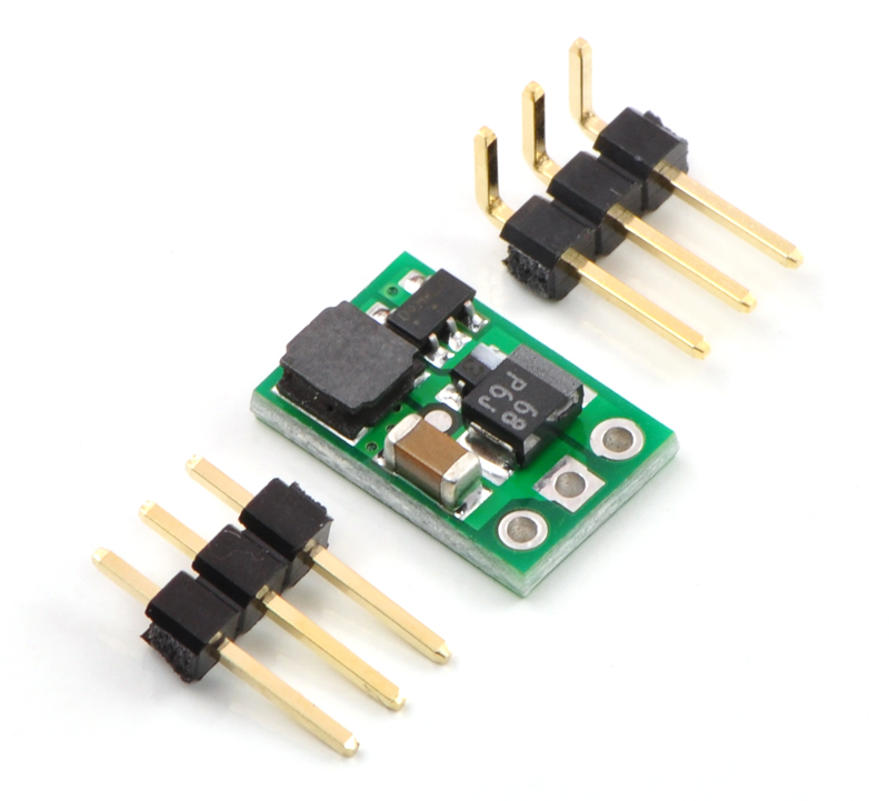
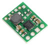
These tiny boost (step-up) switching regulators are based on the NCP1402 boost regulator IC. Their small dimensions of just 0.33" × 0.5" (8.4 mm × 12.7 mm) and a startup voltage of down to 0.8 V make it easy to build 3.3 V and 5 V circuits that are powered by lower battery voltages. The available output current and output voltage ripple depend on the input voltage (see Typical Efficiency and Output Current section below), but the regulator can provide up to 200 mA if the input voltage is high enough.
With low input voltages, the output voltage ripple is under 40 mV peak-to-peak. When the input voltage is close to the output, the output ripple quickly climbs to 150 mV peak-to-peak. Therefore, adding capacitance from the output to ground is recommended for noise-sensitive applications with input voltages close to the output voltage.
Some example applications include:
- Powering 3.3 V or 5 V systems from lower-voltage batteries.
- Powering higher-voltage subsystems in lower-voltage systems (e.g. powering a 5 V sensor in a 3.3 V system).
This regulator is available with a fixed 3.3 V or 5 V output.
For higher-power applications, consider using one of Pololu's adjustable boost regulators or Pololu's U3V12Fx boost regulators. For a regulator that supports similarly low input voltages but higher currents, consider Pololu's U1V11x boost regulators, which offer features that the rest of Pololu's boost regulators lack, such as a true shutdown and automatic linear down-regulation when the input voltage exceeds the output voltage.
Using the Boost Regulator
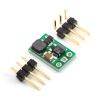
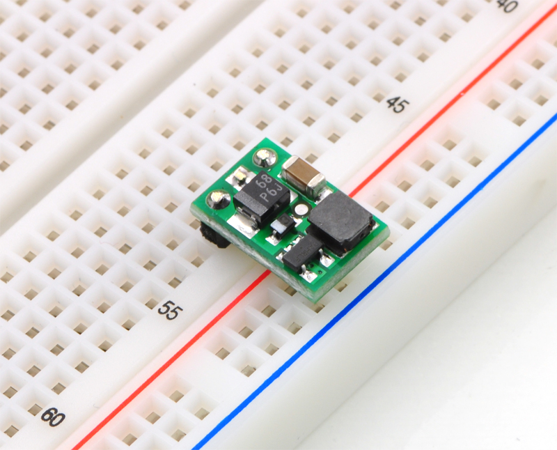
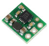
The boost regulator has just three connections: the input voltage, ground, and the output voltage. These three connections are labeled on the back side of the PCB and they are arranged with a 0.1" spacing along the edge of the board for compatibility with standard solderless breadboards and perfboards and connectors that use a 0.1" grid. You can solder wires directly to the board or solder in either the 3×1 straight male header strip or the 3×1 right-angle male header strip that are included.
Feature summary
- Operating voltage: 0.8 V – VOUT
- 3.3 V or 5.0 V output with 2.5% accuracy
- <3 mA typical no-load quiescent current
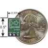
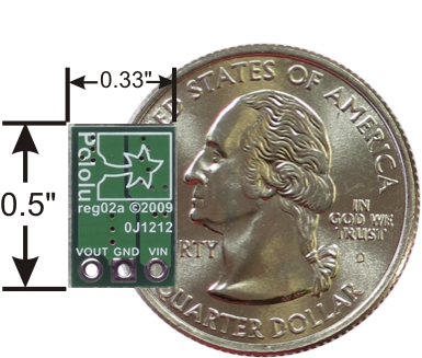
- Small size: 8.4 mm × 12.7 mm × 3.8 mm (0.33" × 0.50" × 0.15")
- Weight without header pins: 0.6 g (0.02 oz)
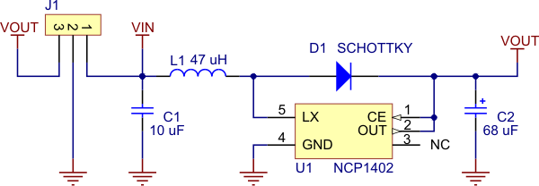 |
Pololu step-up voltage regulator NCP1402 schematic diagram. |
|---|
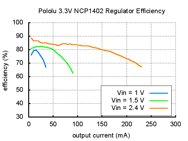
Typical Efficiency and Output Current
The efficiency of a voltage regulator, defined as (Power out)/(Power in), is an important measure of its performance, especially when battery life or heat are concerns. As shown in the graphs below, this switching regulator typically has an efficiency of 75% to 90%.
 |
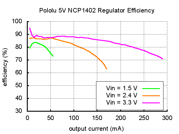 |
The maximum achievable output current is approximately proportional to the ratio of the input voltage to the output voltage. With a 0.8 V input, approximately 5 mA are available before the output voltage begins dropping. The full 200 mA output can be realized from input voltages over approximately 2.4 V (3.3 V version) or 2.7 V (5 V version). Additionally, the maximum output current can depend on other factors, including the ambient temperature, air flow, and heat sinking.
LC Voltage Spikes
When connecting voltage to electronic circuits, the initial rush of current can cause damaging voltage spikes that are much higher than the input voltage. In Pololu's tests with typical power leads (~30" test clips), input voltages above 4 V caused voltage spikes in excess of 6 V, the absolute maximum voltage of the NCP1402. You can suppress such spikes by soldering a 33 µF or larger electrolytic capacitor close to the regulator between VIN and GND.
More information about LC spikes can be found in Pololu's application note, Understanding Destructive LC Voltage Spikes.
People often buy this product together with:
 | Vibration Motor 11.6×4.6×4.8mm |
 | Pololu 3.3V Step-Up Voltage Regulator U1V11F3 |
 | Pololu 3.3V Step-Up Voltage Regulator U1V10F3 |
Dimensions
| Size: | 0.5" x 0.33" x 0.15"1 |
|---|---|
| Weight: | 0.6 g1 |
General specifications
| Minimum operating voltage: | 0.8 V |
|---|---|
| Maximum operating voltage: | 3.3 V |
| Maximum output current: | 200 mA2 |
| Output voltage: | 3.3 V |
| Reverse voltage protection?: | N |
| Maximum quiescent current: | 1 mA3 |
Identifying markings
| PCB dev codes: | reg02a |
|---|---|
| Other PCB markings: | 0J1212 |
Notes:
- 1
- Without included optional headers.
- 2
- This is a function of the boost voltage: the greater the step-up voltage, the less current the unit can supply.
- 3
- With no load. Actual quiescent current depends on input voltage.
File downloads
-
NCP1402 Datasheet (208k pdf)
-
Drill guide for Pololu Step-Up Voltage Regulator NCP1402 (19k dxf)
This DXF drawing shows the locations of all of the board’s holes.
Exact shipping can be calculated on the view cart page (no login required).
Products that weigh more than 0.5 KG may cost more than what's shown (for example, test equipment, machines, >500mL liquids, etc).
We deliver Australia-wide with these options (depends on the final destination - you can get a quote on the view cart page):
- $3+ for Stamped Mail (typically 10+ business days, not tracked, only available on selected small items)
- $7+ for Standard Post (typically 6+ business days, tracked)
- $11+ for Express Post (typically 2+ business days, tracked)
- Pickup - Free! Only available to customers who live in the Newcastle region (must order online and only pickup after we email to notify you the order is ready). Orders placed after 2PM may not be ready until the following business day.
Non-metro addresses in WA, NT, SA & TAS can take 2+ days in addition to the above information.
Some batteries (such as LiPo) can't be shipped by Air. During checkout, Express Post and International Methods will not be an option if you have that type of battery in your shopping cart.
International Orders - the following rates are for New Zealand and will vary for other countries:
- $12+ for Pack and Track (3+ days, tracked)
- $16+ for Express International (2-5 days, tracked)
If you order lots of gear, the postage amount will increase based on the weight of your order.
Our physical address (here's a PDF which includes other key business details):
40 Aruma Place
Cardiff
NSW, 2285
Australia
Take a look at our customer service page if you have other questions such as "do we do purchase orders" (yes!) or "are prices GST inclusive" (yes they are!). We're here to help - get in touch with us to talk shop.
Have a product question? We're here to help!
Guides

The Maker Revolution
Projects

The Rats Nest VCC Desktop Power Supply

Remote-Controlled Mars Rover

FlipperMate: Hands-Free Pinball

Makers love reviews as much as you do, please follow this link to review the products you have purchased.
Product Comments