
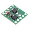


MAX14870 Single Brushed DC Motor Driver Carrier
Available with a lead time
Expect dispatch between Aug 04 and Aug 07
Quantity Discounts:
- 10+ $17.50 (exc GST)
- 25+ $16.95 (exc GST)
 |
MAX14870 Single Brushed DC Motor Driver Carrier, bottom view with dimensions. |
|---|
The MAX14870 from Maxim Integrated is a tiny H-bridge motor driver IC that can be used for bidirectional control of one brushed DC motor at 4.5 V to 36 V. It can supply up to about 1.7 A continuously and can tolerate peak currents up to 2.5 A for a few seconds, making it a good choice for small motors that run on a wide range of voltages. The MAX14870 is a great IC, but its small surface-mount package makes it difficult for the typical student or hobbyist to use; Pololu's breakout board makes it easy to use with standard solderless breadboards and 0.1" perfboards. Since this board is a carrier for the MAX14870, Pololu recommend careful reading of the MAX14870 datasheet (492k pdf). The board ships populated with SMD components, including the MAX14870 and a reverse battery protection circuit.
Pololu also carry a dual MAX14870 motor driver shield that makes it easy to incorporate this great driver into an Arduino project, as well as a dual MAX14870 motor driver for the Raspberry Pi (available with connectors included but not soldered or with connectors soldered for use with a Raspberry Pi).
For similar motor drivers that operate at lower voltages, consider Pololu's BD65496MUV and DRV8838 motor driver carriers.
Features
- Single-channel H-bridge motor driver with shoot-through protection and internal free-wheeling diodes (can drive one DC motor)
- Motor supply voltage: 4.5 V to 36 V
- Output current: up to 1.7 A continuous (2.5 A peak)
- No separate logic supply needed; inputs are 3V- and 5V-compatible
- Simple two-pin DIR/PWM interface (one pin controls direction and another controls speed)
- Under-voltage lockout and protection against over-current/short-circuit and over-temperature
- Carrier board adds reverse-voltage protection
- Active-low fault output indicates over-current or over-temperature condition
- Surface-mount resistor can optionally be added to enable automatic current limiting
- Compact size (0.6"×0.5")
Included hardware
|
|


Two 1×5-pin breakaway 0.1" male headers are included with the MAX14870 motor driver carrier, which can be soldered in to use the driver with breadboards, perfboards, or 0.1" female connectors. (The headers might ship as a single 1×10 piece that can be broken in half.) The right picture above shows the two possible board orientations when used with these header pins (parts visible or silkscreen visible). You can also solder your motor leads and other connections directly to the board.
Using the motor driver
 |
Minimal wiring diagram for connecting a microcontroller to a MAX14870 Single Brushed DC Motor Driver Carrier. |
|---|
Motor and power connections are made on one side of the board and control connections are made on the other. The driver requires an operating voltage between 4.5 V and 36 V to be supplied to the reverse-protected power input, VIN. The VM pin provides convenient access to the reverse-protected supply voltage.
The MAX14870 offers a simple two-pin DIR/PWM control interface, where the DIR pin determines the motor direction and the PWM pin can be supplied with a PWM signal to control the motor speed. The PWM control input is pulled low on the carrier board through a 100 kO pull-down resistor. When the PWM pin is low, the motor outputs are both shorted to ground, which results in dynamic braking of a connected motor.
The EN pin can be driven high to turn off motor outputs, which is useful if you want to let the motor coast. The EN pin is pulled low through a 100 kO pull-down resistor on the carrier board so that the driver is enabled by default.
The following simplified truth table shows how the driver operates:
| EN | PWM | DIR | M1 | M2 | operating mode |
|---|---|---|---|---|---|
| 1 | X | X | high-impedance | high-impedance | coast (outputs floating/disconnected) |
| 0 | 1 | 0 | GND | VIN | “reverse” |
| 0 | 1 | 1 | VIN | GND | “forward” |
| 0 | 0 | X | GND | GND | brake low (outputs shorted to ground) |
This carrier board can also be used with Maxim’s MAX14872 motor driver IC, which is a pin-compatible alternative to the MAX14870. The MAX14872 has the same functionality and performance as the MAX14870, but it offers a different control interface. The two parts share the same datasheet (492k pdf), which makes it easy to directly compare the two. If you are looking for a MAX14872 carrier, you can swap out the MAX14870 on one of these boards for a MAX14872 (if you have the appropriate surface-mount rework tools), or Pololu might be able to manufacture a high-volume custom batch for you. If you are interested in this latter option, please contact us.
Pinout
 |
| PIN | Default State | Description |
|---|---|---|
| VIN | Reverse-protected power supply input; supply this pin with 4.5 V to 36 V. | |
| GND | Ground connection points for the power supply and control signals. The control source and the motor driver must share a common ground. | |
| VM | This pin gives access to the motor power supply after the reverse-voltage protection MOSFET (see the board schematic below). It can be used to supply reverse-protected power to other components in the system. This net connects to the pin labeled “VDD” in the MAX14870 datasheet. | |
| M1 | H-bridge output 1. | |
| M2 | H-bridge output 2. | |
| PWM | LOW | Speed control input; logic high causes the motor to drive. |
| DIR | Direction control input | |
| FAULT | FLOATING | Open-drain, active-low fault output. This pin goes low during an over-current or over-temperature condition. You must use an external pull-up resistor to give this pin a default high value if you want to use it. |
| EN | LOW | Active-low enable input; drive high to tri-state the driver outputs. |
Optional current limiting
The MAX14870 IC features a SNS input that can be used for optional automatic current limiting. By default, this input is connected to ground on the carrier board, which bypasses the current regulation feature. To enable current limiting, you must first cut the trace between the two unpopulated 1206 resistor pads on the top side of the carrier board:
 |
Then, you will need to add your own appropriate surface-mount 1206 resistor to these pads. An example of this is shown below:
 |
The driver tries to keep the voltage on the SNS pin from exceeding 100 mV, so for example, a 100 mO resistor limits the current to 1 A and a 200 mO resistor limits it to 0.5 A. For more information on current limiting, see the MAX14870 datasheet (492k pdf).
Real-world power dissipation considerations
The MAX14870 datasheet recommends a maximum continuous current of 2.5 A. However, the chip by itself will typically overheat at lower currents. In Pololu's tests, Pololu found that the chip was able to deliver 2.5 A for only a few seconds before the chip’s thermal protection kicked in and disabled the motor outputs; a continuous current of 1.7 A was sustainable for many minutes without triggering a thermal shutdown.
The actual current you can deliver will depend on how well you can keep the motor driver cool. The carrier’s printed circuit board is designed to help with this by drawing heat out of the motor driver chip. Pololu's tests were conducted at 100% duty cycle with no forced air flow; PWMing the motor will introduce additional heating proportional to the frequency.
This product can get hot enough to burn you long before the chip overheats. Take care when handling this product and other components connected to it.
Schematic
 |
MAX14870 single brushed DC motor driver carrier schematic diagram. |
|---|
This schematic is also available as a downloadable pdf (138k pdf).
People often buy this product together with:
 | DRV8838 Single Brushed DC Motor Driver Carrier |
 | Magnetic Encoder Pair Kit for Micro Metal Gearmotors, 12 CPR, 2.7-18V |
Dimensions
| Size: | 0.6" × 0.5"1 |
|---|---|
| Weight: | 0.5 g1 |
General specifications
| Motor driver: | MAX14870 |
|---|---|
| Motor channels: | 1 |
| Minimum operating voltage: | 4.5 V |
| Maximum operating voltage: | 36 V |
| Continuous output current per channel: | 1.7 A2 |
| Peak output current per channel: | 2.5 A |
| Maximum PWM frequency: | 50 kHz |
| Reverse voltage protection?: | Y |
Identifying markings
| PCB dev codes: | md30a |
|---|---|
| Other PCB markings: | 0J8951 |
Notes:
File downloads
-
Maxim Integrated MAX14870 DC motor driver datasheet (492k pdf)
-
MAX14870 single brushed DC motor driver carrier schematic diagram (138k pdf)
Printable schematic for the MAX14870 single brushed DC motor driver carrier.
-
Dimension diagram of the MAX14870 Single Brushed DC Motor Driver Carrier (280k pdf)
-
3D model of the MAX14870 Single Brushed DC Motor Driver Carrier (3MB step)
-
Drill guide for MAX14870 Single Brushed DC Motor Driver Carrier (22k dxf)
This DXF drawing shows the locations of all of the board’s holes.
Recommended links
-
Maxim Integrated MAX14870 product page
Maxim Integrated’s product page for the MAX14870, where you can find the latest datasheet and additional resources.
Exact shipping can be calculated on the view cart page (no login required).
Products that weigh more than 0.5 KG may cost more than what's shown (for example, test equipment, machines, >500mL liquids, etc).
We deliver Australia-wide with these options (depends on the final destination - you can get a quote on the view cart page):
- $3+ for Stamped Mail (typically 10+ business days, not tracked, only available on selected small items)
- $7+ for Standard Post (typically 6+ business days, tracked)
- $11+ for Express Post (typically 2+ business days, tracked)
- Pickup - Free! Only available to customers who live in the Newcastle region (must order online and only pickup after we email to notify you the order is ready). Orders placed after 2PM may not be ready until the following business day.
Non-metro addresses in WA, NT, SA & TAS can take 2+ days in addition to the above information.
Some batteries (such as LiPo) can't be shipped by Air. During checkout, Express Post and International Methods will not be an option if you have that type of battery in your shopping cart.
International Orders - the following rates are for New Zealand and will vary for other countries:
- $12+ for Pack and Track (3+ days, tracked)
- $16+ for Express International (2-5 days, tracked)
If you order lots of gear, the postage amount will increase based on the weight of your order.
Our physical address (here's a PDF which includes other key business details):
40 Aruma Place
Cardiff
NSW, 2285
Australia
Take a look at our customer service page if you have other questions such as "do we do purchase orders" (yes!) or "are prices GST inclusive" (yes they are!). We're here to help - get in touch with us to talk shop.
Have a product question? We're here to help!
 Standard Duty 30A Blade Fuse HolderSKU: CE07848Standard duty blade fuse holder. Easy install, just cut loop and connect to your ...

Guides

The Maker Revolution
Projects

The Rats Nest VCC Desktop Power Supply

Remote-Controlled Mars Rover

FlipperMate: Hands-Free Pinball

Makers love reviews as much as you do, please follow this link to review the products you have purchased.
Product Comments