Cameras in combination with artificial intelligence create arguably the most powerful sensor you can ever put on a microcontroller. So that’s exactly what we will do here with an ESP32-CAM Development Board that sports an inbuilt 2MB camera. ESP32 boards are the current IoT gold standard for getting WIFI connectivity into your projects and, because of this, they come in many types and variants. ESP32 boards have become the most versatile WiFi Microcontroller boards available. Makers everywhere have started using their chips in development boards, embedded projects, and commercial solutions, so it is about time we did too!
Recently ESP32 Development boards have started adding all kinds of extra bells and whistles. DFRobot swooped in with the fantastic ESP32-CAM Development board. This board is an ideal solution for IoT applications, prototype constructions, and DIY projects that involves video. You even have the capability to run Edge Deep Machine Learnt (AI) systems using this board.
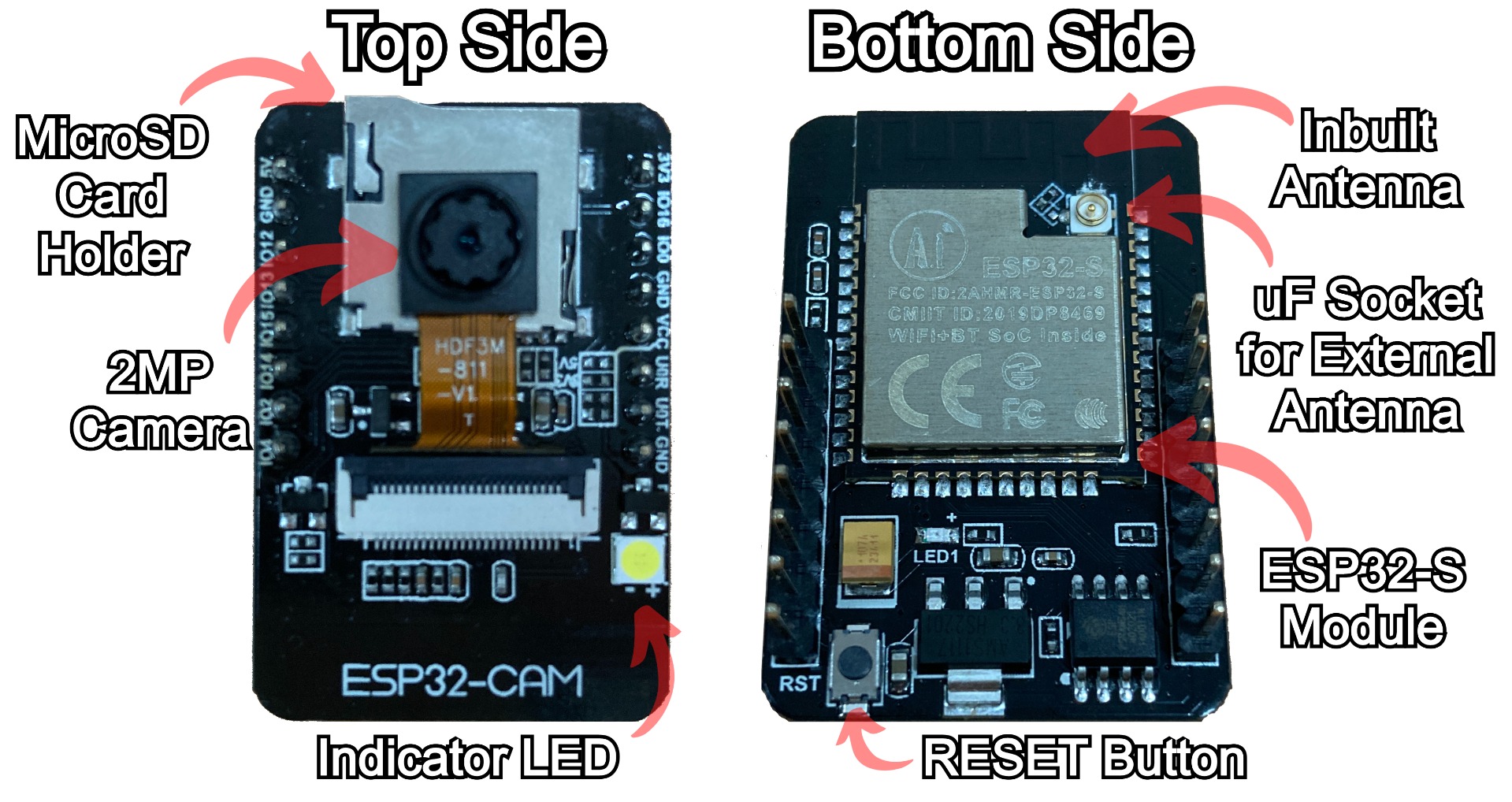
With today's completed system you will require only this board and 5V 2A Power-In to create a fast and robust video stream throughout your local network. This means you can quickly slap this module onto any robotics project and you will be able to see the wide-world direct from the perspective of your robot. Or you can pop it into the corner of your office and you have instantly created a viable security camera that could save video straight to a Micro-SD card. See an annotated image of both sides of the ESP32-CAM development board below.
The content of this guide can be seen below.
- What You Need
- Setting up the ESP32-CAM to be Programmed
- Arduino IDE Set Up for ESP32-CAM
- Procedure to Flash ESP32-CAM
- ESP32-CAM Demonstration
- Where to Now, Attach to Zumo 32U4 Robot, 3D Printed Case, and Audio Capture
- Downloads
These boards do require some finesse to wrangle them into performing exactly how we want. As they are micro-controllers so we will need to upload our scripts to the ESP32-CAM non-volatile flash memory. Non-volatile in this context simply means the data is not forgotten when powered down. This process is often referred to as flashing a program to a microcontroller. Arduino IDE is a great method to upload and flash ESP32 and is exactly what we will do here. That means that our scripts are effectively going to be written in the programming language C and C++. Often development boards will have USB connectivity in-built however our stripped-back ESP32-CAM board has only UART (universal asynchronous receiver-transmitter). Thus we will require a USB to UART Converter to correctly flash the ESP32-CAM when we plug it into the USB of our computer. This may sound complex but I will walk you through each step. Check the ESP32 Development Module below as well as it streaming live video to my computer all through the WIFI and running face detection!

Development boards with ESP32 modules embedded are the current gold standard for achieving effective IoT WIFI connectivity at a price point that is excellent. If you happen to be holding an ESP32 board and want to know exactly what type it is come check out this guide here.
As always if you have any questions, queries, or things to add please let us know your thoughts!
What You Need
Below is everything you need to get started streaming live video from your ESP32-CAM Development Board.
- ESP32-CAM Development Board
- USB to UART Programmer (can use a SparkFun Serial Basic Breakout - CH340G, an ESP-PROG, or an Arduino UNO)
- 5V 4A Power Supply (2A is minimum)
- Female DC Power Jack
- Jumper Wires (Male to Female, Male to Male)
- Breadboard
Setting up the ESP32-CAM to be Programmed
The first step is to set up the hardware in a way that we can flash our ESP32-CAM board. If we were to plug in a 5V wire and a ground wire to the board it would not do anything as we haven't instructed it to do anything. Instructions come in the form of Programming scripts. To get these instructions (I also like the think of instructions as recipes) onto our ESP32-CAM we need to set it up so that it can receive UART data. We will utilise the Arduino IDE software so this data will come out of our computer from a USB port into the ESP32-CAM development board. Thus we will need some way of translating USB data into UART data.
There are boards created to do exactly this task, like this SparkFun Serial Basic Breakout - CH340G. We can also use an Arduino UNO to facilitate correct USB to UART translation and communication. To activate this secret Arduino Uno Power connect any | Ground | pin to the | Reset | pin on the Arduino board with a jumper wire. This allows you to use the UNO as though it were a USB to TTL (UART) serial cable. For a whole bunch of knowledge on programming with USB-Serial Converters check this linked guide. Below are the schematics for setting up the ESP32-CAM for programming with either a USB to UART Adapter or an Arduino UNO.
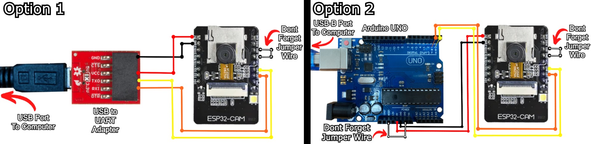
Below shows the ESP32-CAM wired up with either a USB to TTL (Transistor-Transistor Logic) Serial UART RS232 Adaptor or an Arduino UNO and ready to flash. Note that the ESP32-CAM board is situated in a way that you can still access the | RST | button found on the bottom side of the board, you will need to access to press this button during the flash stage to get the board into bootloader mode.

In my configuration above RX goes to TX (UOT) and TX goes to RX (UOR). Sometimes with these ESP32-CAM boards, the UOR and UOT Pins are swapped (without updating the Pinout text written to the PCB). So, during the next chapter, if you are having connectivity issues or hangs when trying to upload swap the RX and TX connections (Yellow and Orange wires) on the ESP32-CAM board. If these two wires are connected up backward and then the system is powered up it will not break your microcontroller. You can freely trial and error.
You might also need to press the ESP32-CAM on-board RESET button multiple times to restart your ESP and print the IP address during boot. Arrange your ESP32-CAM onto the Breadboard so you can access and press the |RST| Reset button.
Arduino IDE Set Up for ESP32-CAM
Now, lets set up our computer so we can quickly program our ESP32-CAM exactly how we want.
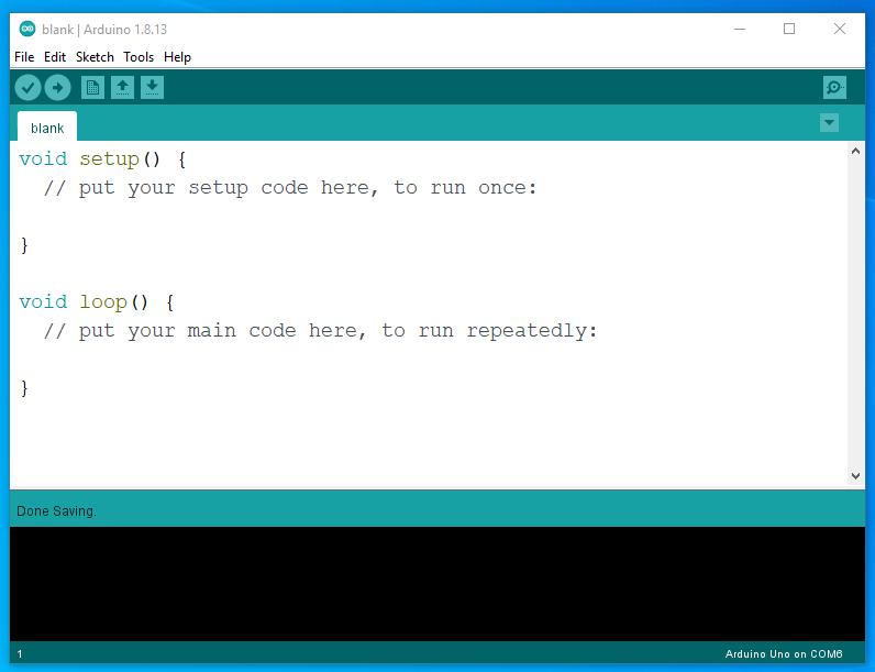
First step is installing Arduino IDE software onto our computer. The Arduino Integrated Development Environment (IDE) connects to micro-controller hardware to upload programs and communicate with them. Use this link to jump to the official software download location. With it installed and running it will look like the image below.
With it installed in your system we now need to adjust some settings inside Arduino IDE to be sure we will have all the packages required and be able to perform a successful flash. First, we will add the ESP32 Board Libary to our fresh Arduino IDE installation. Arduino IDE is capable of flashing all kinds of boards we just need to add the functionality. To do this focus on the top toolbar, click on | Files | hover down to | Preferences | and click on it. In this settings menu find the additional boards section. Copy and paste the following into this section | https://raw.githubusercontent.com/espressif/arduino-esp32/gh-pages/package_esp32_index.json |. If you already have something written here separate each with a comma | , |. Then focus back to the top toolbar, click on |Tools|, hover down to | Board |, and click on | Board Manager |. Then in the search bar type the following | esp32 |. When the library of the same name pops up click on the install button. Having done this, we have all the functionality required to make our ESP32-CAM board work with Arduino IDE. See these above steps happening in the image below.

With that complete focus to the top toolbar and click on | Tools |. Adjust the settings found here so that it matches exactly the image below. The only setting that may be slightly different is the Port Number, just be sure to select the one the ESP32-CAM is connected to.

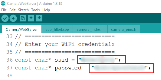
With that complete we now just need the programming scripts to tell our micro-controller what to do. You can find these scripts at the bottom of the page or from the GitHub Repository here! The repository has the potential to update since the writing of the guide. Once you have it downloaded and unzipped on your computer open it by clicking on the | File | button on the top toolbar then hovering down and clicking on | Open... |. Using the newly opened window jump deeper into the directories | ESP32-examples-Camera | and select | CameraWebServer |. We will need to customise the CameraWebServer Script by adding your particular WiFi and WiFi Password credentials. This section can be found in the code from Line 33. Make sure to enclose those details with quotation marks | "YOUR_DETAILS" | and save the script after doing so. See this section in the code with my particular WiFi details that I added blurred out below.
Procedure to Flash ESP32-CAM
With your setup hooked into your computer through the USB port and your Arduino IDE set up correctly with the | CameraWebServer | code opened up and ready it's Time to flash! Click the | Upload | button found on the top left of the interface. This will then compile your code, and send it through to your USB to UART Converter which sends that message into your ESP32-CAM micro-controller. As soon as you see a loading bar in the bottom of the terminal press the reset button on the bottom of the ESP32-CAM board to force it into bootloader mode. Bootloader mode is the mode used for receiving firmware updates. See this button and the loading screen on the image below.
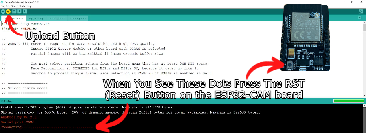
UART is literally 1s and 0s data, it is literally machine code (with a little prefix and addendum to confirm the start and end of transmission)! This process will take less than 5 minutes to complete. For a whole bunch of context on UART Connectivity check out this linked guide. See below for what Arduino IDE will tell you once the uploaded process is complete.

Before progressing any further let us now figure out exactly what IP Address out ESP32-CAM is going to be provided by our Modem/Router. By typing this IP Address into any internet browser of any locally connected device we will be able to access the live camera stream. Focus once more to the top toolbar and click on | Tools |, then hover down and click on | Serial Monitor |. Then after making sure that the baud rate is set to | 115200 baud | and that the jumper wire that connects | Ground | pin to | IO0 | pin is removed from the ESP32-CAM board, press the | RST | (reset) button on the ESP32. Press and hold the button for approximately one second. Having done this the Serial Monitor Window will spit out some details about the connected board and most importantly it will tell you exactly what website to type into your URL. In my case, it was | http:/192.168.1.48 |. See all of this occurring in the image below.
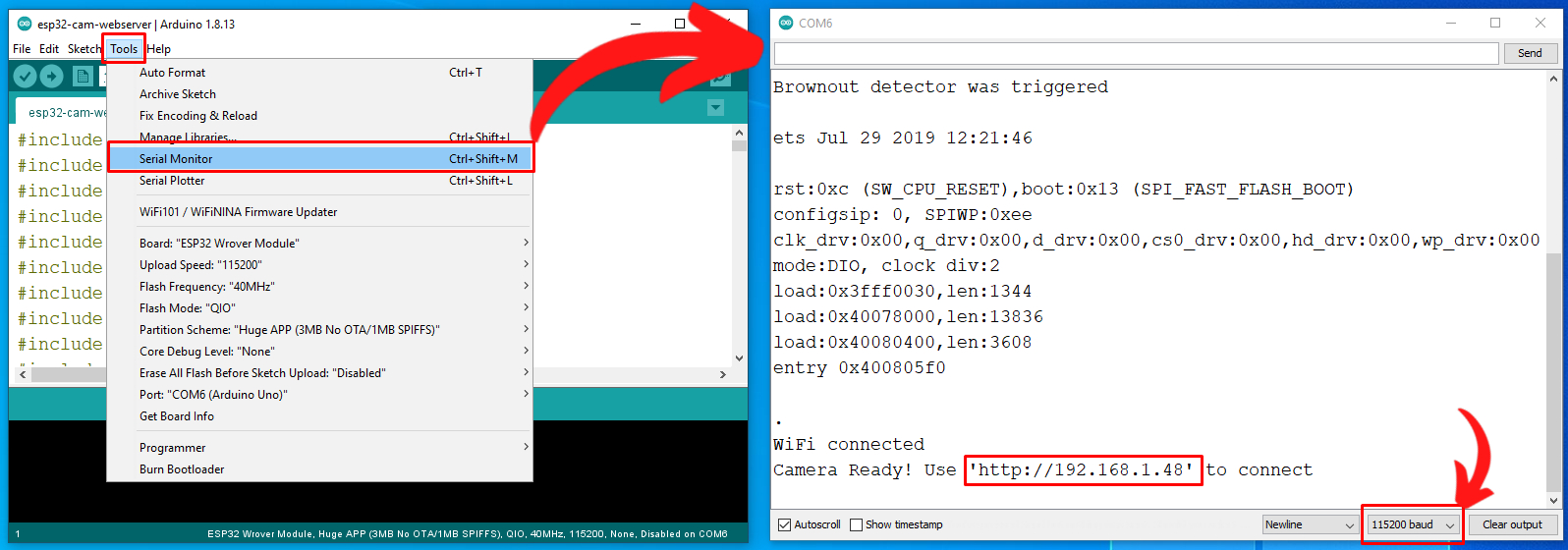
If you don’t select the right baud rate in the Arduino IDE Serial Monitor, you won’t get your board IP address or you will just get gobbledygook gibberish on the screen. The baud rate is the rate at which information is transferred in a communication channel. So make sure you select the right baud rate. In our examples with the ESP32-CAM, we use | 115200 baud |.
As a note, you can also figure out the IP Address of your ESP32-CAM by accessing your Router/Modem Settings. You may find that a simpler/faster approach.
ESP32-CAM Demonstration
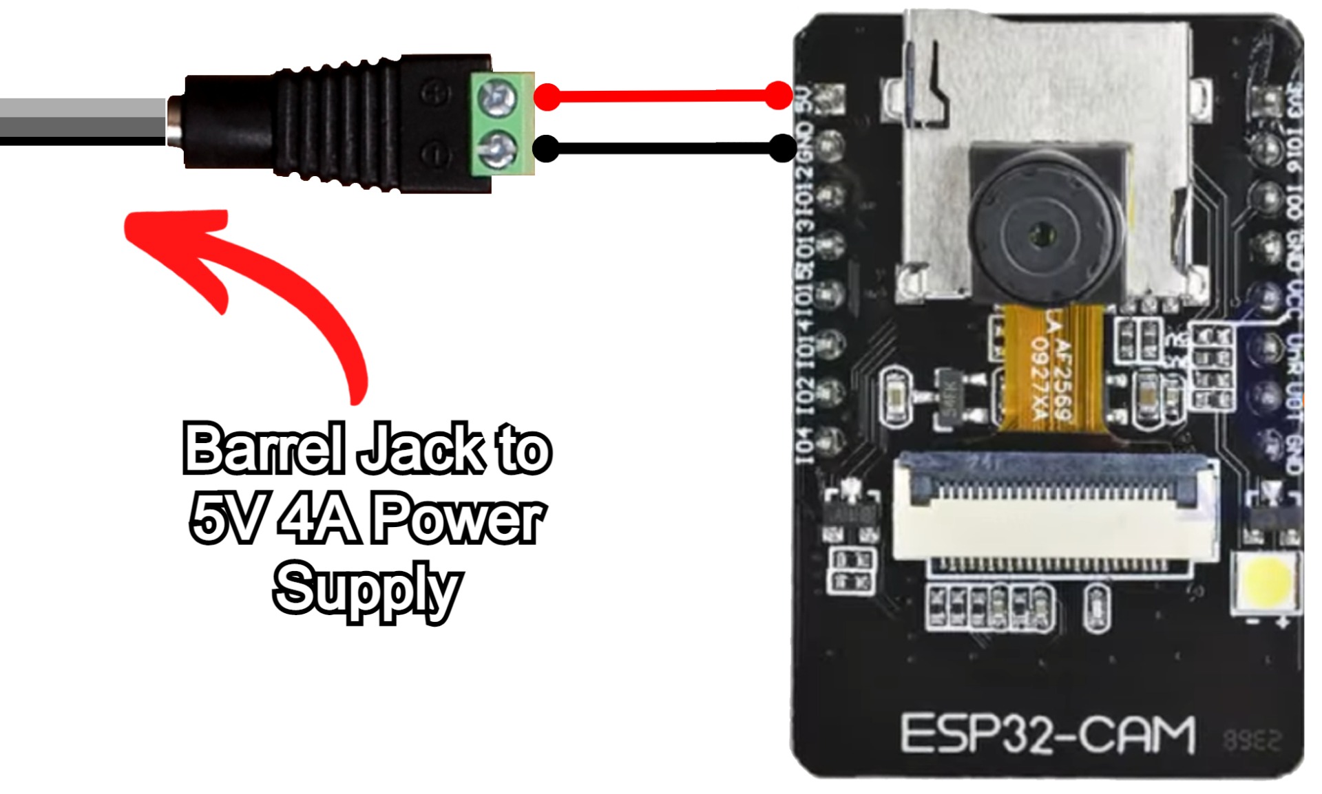
Now, with the software flashed to our ESP32-CAM it's time to play! Hook the ESP32-CAM board up to 5V 2A power and switch it on. Do not forget to remove the ESP32-CAM Jumper Wire. If not removed the board will stay stuck in bootloader mode and not do anything. Bootloader Mode is the mode used for receiving firmware updates, which if you have gotten to this stage you do not need. See the below schematic for exactly this setup.
Now on any locally connected device open up a web browser (Chrome, Safari, or Edge are perfect candidates) and type the IP address you figured out from before straight into the browser. As soon as you do you'll be welcomed by the Graphical User Interface that the ESP32-CAM automatically creates on boot. Scroll down and select Start Stream. As soon as you do your ESP32-CAM Development board will start to live stream a video feed of exactly what the camera sees all through your WiFi! See this in action in the image below.

Heaps of fantastic options here! Every dial that you could want to toggle with a camera module is here and ready to go. You can also lower the resolution and use different forms of Video Stream encoding to increase the Framerate. There's also a very simple Face Recognition AI system built into this software thus we can switch that on and off. You will notice a big dip in FPS (frames per second) when doing this (even with a lower Pixel density), however, it is remarkable that it will work on hardware this stripped back! ESP32 Boards are Sweet! See this face recognition occurring in the image below.

Where to Now, Attach to Zumo 32U4 Robot, 3D Printed Case and Audio Capture
For me, this has to be the easiest way to get eyes on the ground for your projects. To have a complete package of Camera and Video streaming that starts as soon as 5V power is phenomenal. ESP32-CAM boards have been utilised to provide UI remote control for robotic projects as well.
Check the below image to see the ESP32-CAM Development board mounted and powered by a battery-powered Zumo 32U4 Robot. The 5 Volt and Ground Pin were the only parts modified on the Zumo. The ESP32-CAM Module slipped between the metal and plastic on the nose of the treaded vehicle very happily. Now when I drive it around using the little remote I can see exactly what the Zumo robot sees (which, at the time of the photo, happened to be my camouflaged jacket).
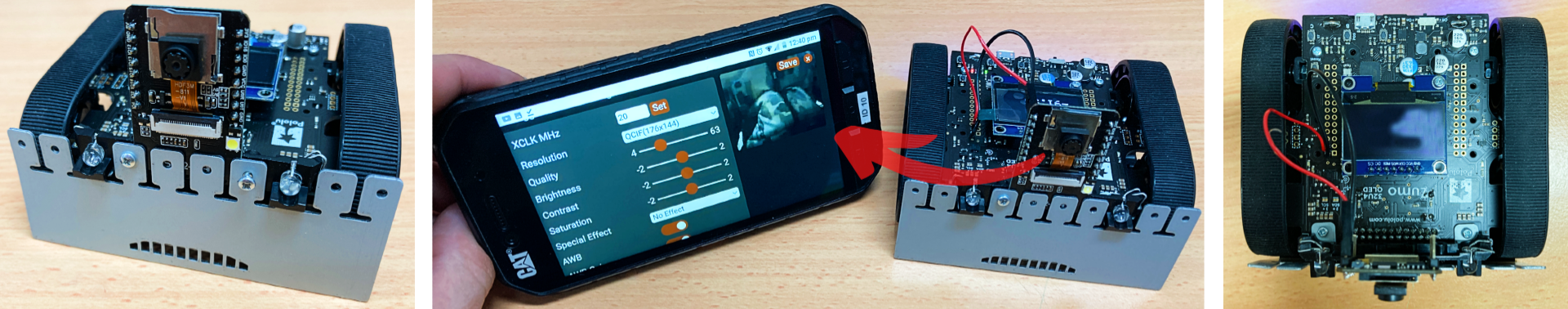
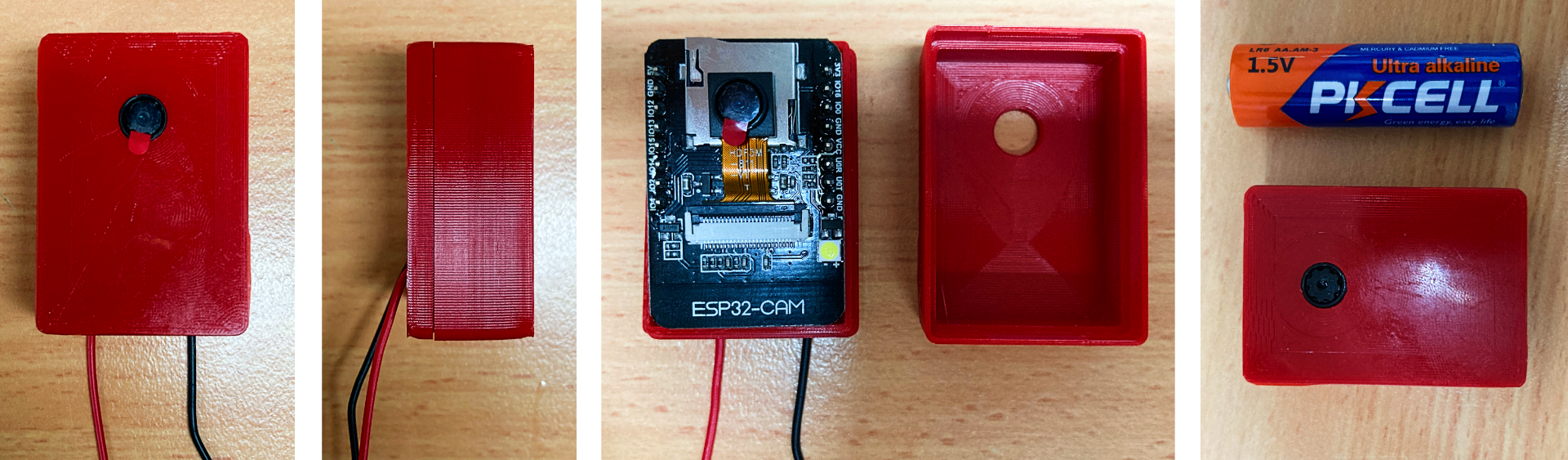
I have also 3D printed several ESP32-CAM cases to figure out which one was best. Usually, these cameras will operate like security cameras so the one I settled on for this article is a simple clean design, something understated, but will provide enough protection from everyday indoor life. Below is one of the cases created using an Ultimaker 2+ 3D Printer and Ultimaker Red CPE. If you want to 3D Print the same case the STL file for this ESP32-CAM case can be found here.
You also have the option of adding Audio to this system. The ESP32-CAM board is capable of having I2S Audio MEMs Microphone attached to it via the GPIO Pins. Then you will be able to record Audio and Video simultaneously to your Micro-SD. The programming code that you will need to flash your ESP32-CAM board to achieve this can be located here along with a Hardware hook-up guide.
Here is another great video guide demonstrating multiple ESP32-CAM Boards transmitting data to an Android Tablet. He (That Project) even installs them into Fake Camera Frames and added recording functionality. Very rad and many other fantastic projects worth checking out there too.
Downloads
Below is a download link for all the scripts utilised in this guide. For ideas on where to go next with this ESP32-CAM Board check out this video of ESP32-CAM WiFi Range Testing - 10km using Directional Antenna. Proper remarkable

