Break your television and monitors free from the confines of their edges with Hyperbian! This is an open-source ambient light software that will improve the way you enjoy your favourite media.
Hyperion for the Raspberry Pi ∴ Hyperion + Raspbian = Hyperbian!
Let me show you exactly how I set up my Ambilight set-up here and teach you how you can do something similar at home. And all without soldering! The contents of this guide can be seen below.
- Images of Final Result
- What You Need
- Schematics
- The Build
- Preparing the Micro-SD Card and Connecting to the Internet Headless
- Accessing and Altering the Settings
- List of Compatible USB HDMI Capture Devices
There is a lot of differing information out there but I will show you exactly what I used and how you can do it too. This is a very sweet setup that you can have too! The example here has 250 LEDs on the back of a little monitor but you do not need to use such a dense LED strip to get a great effect. One major point to remember. This will only work for HDMI devices and will not work for your Television's native UI.
You can also use this setup as an eye strain relief particularly if you are like me watching movies in the dark, I find my eyes get tired faster than if the house lights are on. If you project a simple soothing yellow tone behind your television it will ease pressure on your eyes and let you get to sleep faster after your movie.
As always if you have any questions, queries, or things to add please let us know your thoughts!
Images of Final Result
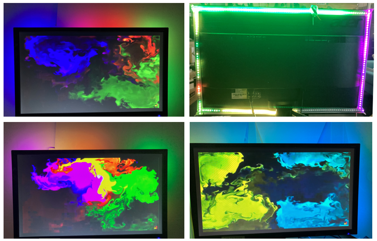
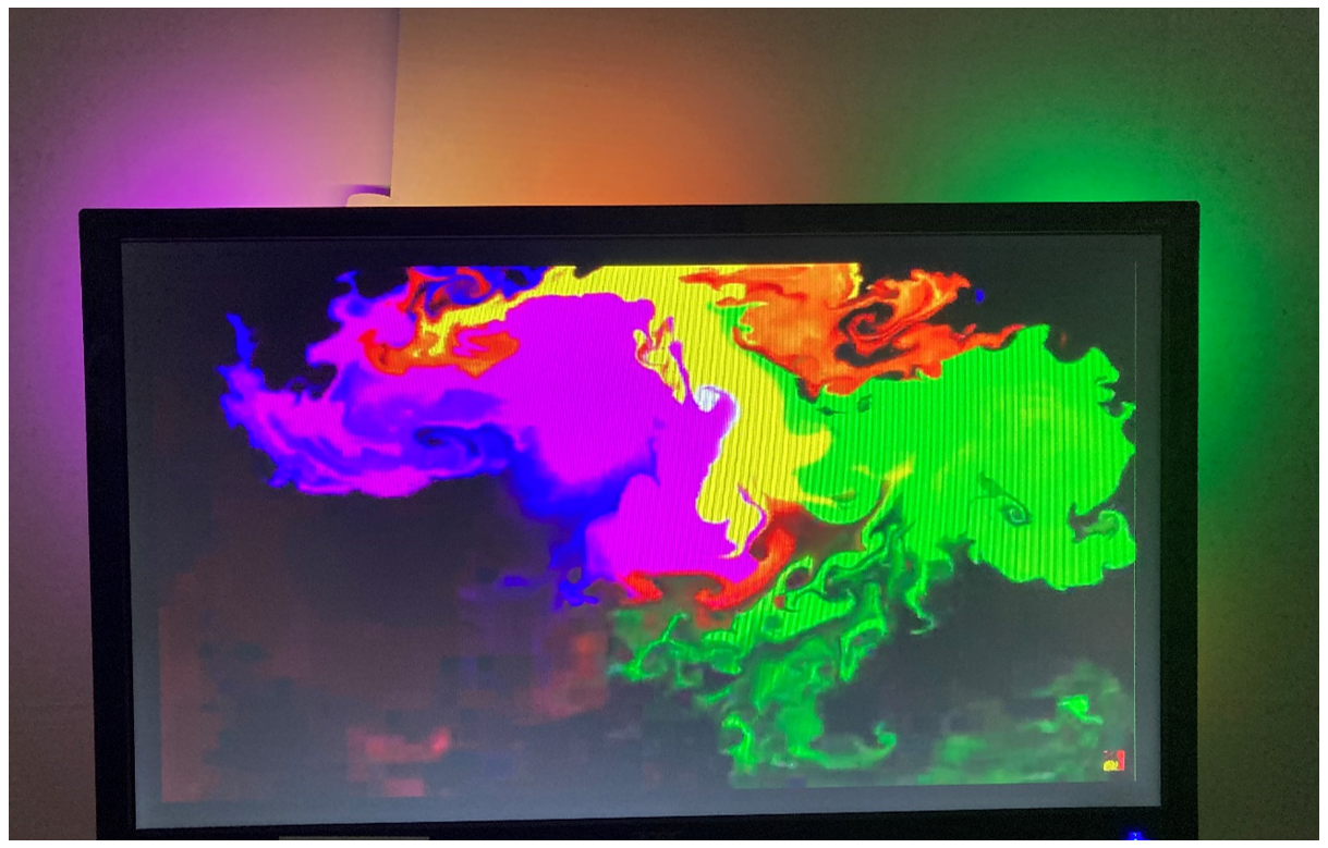
Below is a series of images showing you exactly what the effect will look like on your monitor or TV and you can see how I have arranged the LEDs on the back of the monitor. Looking pretty nice! Static images do not do this setup justice. I used a seriously dense amount of LEDs on the back of this small monitor, you do not need to go this dense particularly as the wall behind the TV will be acting as a surface to diffuse the light. But it is nice seeing how packed in we can get these LEDs nowadays.
What You Need
Below is a list of what you will need and at the bottom some things that you may want for your setup.
- Neopixel (WS2812B) Full Addressable LED Strip (I would recommend not using as dense LED as I have as the light will disperse and using this many LEDs does take some current)
- Raspberry Pi 4 Model B (I have been using a 2 GB). You can do it with older Pi’s but there may be a slight delay to the LEDs colours unless the resolution being captured by the HDMI USB Capture Card is turned right down.
- HDMI Cords x 3
- Micro-SD 16GB Card (and a way to attach it to a computer so you can flash it)
- HDMI Splitter
- Raspberry Pi Case (I use my ONESIE 3D Printable Case)
- 3 Jumper Wires Male to Female
- Double-Sided Tape or Velcro
- Optional: Zipties, Hippo Clips or Solder + Soldering Iron and Wires (depending on if you want to fold the LED strip or solder the corners)
- Optional: A HDMI Switcher would be a good addition to the build if you want multiple sources of HDMI to work seamlessly
Schematics
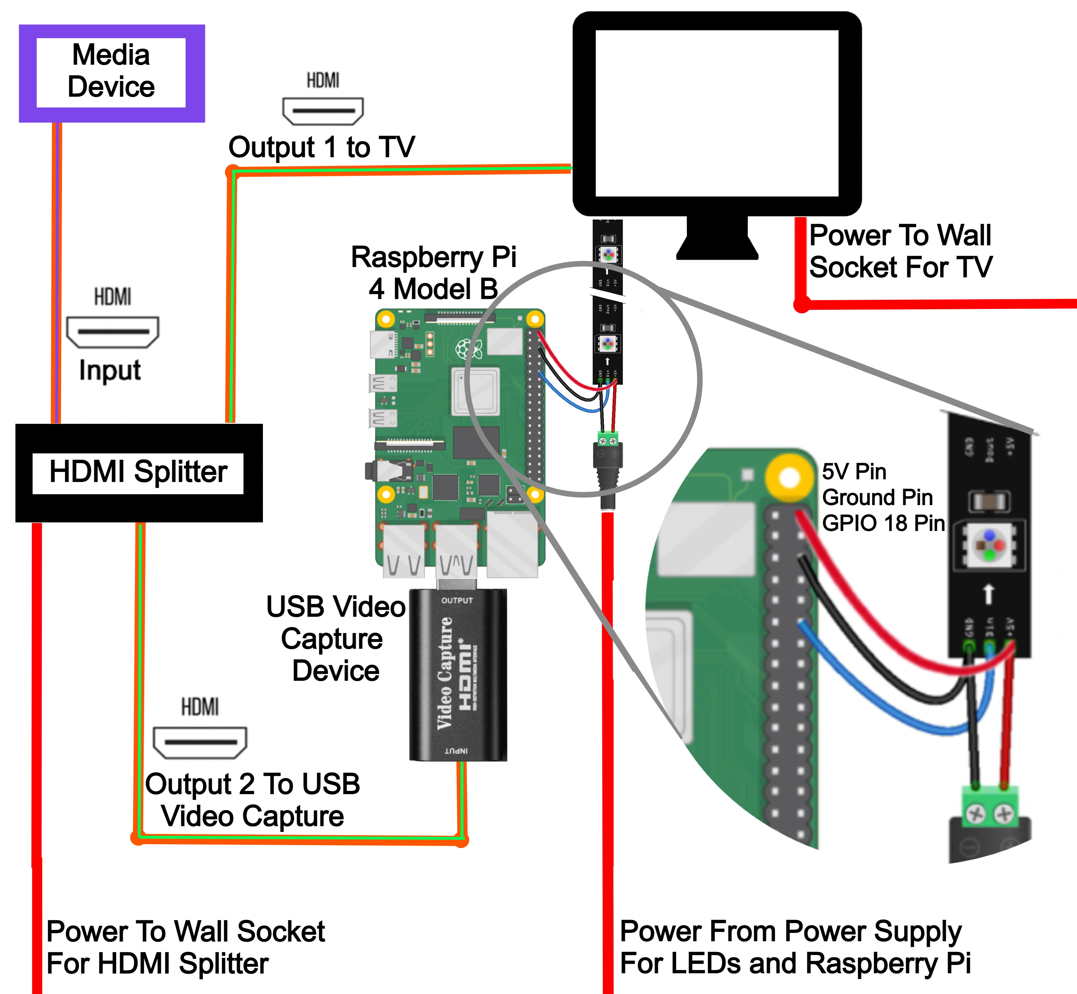
So the best way to approach this to have a plan and there no better way to portray a plan than a good schematic. Below is a diagram of exactly my setup here. Keep in mind the HDMI USB Capture Card has been plugged directly into the Raspberry Pi 4 using a USB Port.
The pins being used on the Raspberry Pi are a 5V Pin for powering it, a shared ground with the LEDs, and GPIO Pin 18 to send the information to the LEDs on what colour they should produce. Some people would say powering the Pi in this manner puts it at risk of power and current surges and would instead remove that 5V power pin and power the Pi through the USB-C cord (by chopping up a USB – C cord and plugging the Positive and negative into the DC Jack with the Positive and negative from the LED strip inserted as well. Or if concerned you could incorporate a Diode to the setup. It is up to you, I have had no issues so far running it this way.
The Build
Attaching the LED Strips to the back of the monitor I have done using double-sided tape and folding the LED strip around itself to make the corners and then securing the corner with zip ties. My LED strips that I have used here were only 1 metre long so I had to combine two strips together. I did this using the connectors and hardware already attached then taping it together. This does affect the light a little however if I wanted to fix this you could pull out the soldering iron, solder, and some wires and tidy it all up. But this project we are keeping solder-free!
Further is an image of all the connections that need to be made for this setup. First shows the HDMI splitter with the white cord being the input, one black cord going to the USB HDMI Recorder, and another going to the Monitor. The second shows the connection to the LEDs and Raspberry Pi and the LEDs to the Power Supply. The third and the fourth show the connection of the Jumper wires to each specific Raspberry Pi Pin.
Strip the two wires without connections coming from the LED just a little so they can connect to the DC power jack. The white cable is the negative so screw it into the negative of the DC power jack and the Red is the positive power so similarly screw it into the Positive jack.
Focusing on the wires coming off the LED strip, the ones which have a connection, attach jumper cables to each (is always good practise to use the same colours).
The red wire is the power wire which I attach to the 5V power of the Pi. If you are using a larger power supply than the 4 Amps I have here I would power the Raspberry Pi instead via the official USB-C power supply and not connect this red wire. The Green wire is the signal wire which I attached to GPIO 18 Pin on the Raspberry Pi. The White wire is the ground of the GPIO Pin which I attach to a ground pin of the Raspberry Pi.
Below is an image of the power into this setup, one going to the splitter, one going to the monitor, one going to the LEDs.
Preparing the Micro-SD Card and Connecting to the Internet Headless
The first step is Flashing the SD Card with the most current version of Hyperbian (download link found here). A great place to learn how to do this can be found here. Once that is complete we will turn on SSH and provide the Raspberry Pi with Internet Network details via files we will leave in the boot folder. Having done this when we turn the Pi on it will create an Options Menu which we can access from any device on our network by typing to the URL the | IP Address of the Pi:8090 |. A great place to learn how to do this can be found at this guide here.
Accessing and Altering the Settings
Start by opening up the LED Hardware Tab which looks like the image below and do the following tasks.
• Change the Controller Type to WS281X in the LED Controller Tab
• Change RGB Byte Order to GRB in the LED Controller Tab
• Configure the number of LEDs you have in your set up in the LED Controller Tab
• Configure where your LEDs start, which direction they go in and how many on each side in the LED Layout Tab.
• Enable the Black Border Detection in the LED Layout tab
Next jump into the Capturing Hardware section to lower the resolution being captured by the USB HDMI Capturing device. I use 720 by 480 Device Resolution. This will result in faster-LED light response times. Also, turn off enable platform capture and turn on enable USB Capture, see image below.
LED Layout Preview menu will give you the max power consumption. This would only occur if all these LEDs go fully white and are at 100%. So because I have way too many LEDs we will need to throttle that power. Here in Image processing under the colour calibration menu, you can lower the max brightness of your LEDs by a percentage value. Under heavy uses, a Raspberry Pi 4 Model B uses a little less than 1 amp so that can be our baseline. We have a 4 amp supply so that leaves us with 3 amps to drive these LEDs. To give us wiggle-room even though this application will never be driving all the LEDs at full brightness we will turn the max brightness to 10 percent but you could go to 15 percent (This is because 19.1 * 15% = 2.865 Amps. Thus 1 + 2.865 = 3.86 Amps which is less than the Maximum 4 Amp from the Power Supply.)
And with that, You are done! Everything should look similar to the image below when you check out your dashboard.
Thus the lights should be functioning properly like in the image below unless you are using one of the many kinds of other effects that you can do with Hyperion. You can find these effects in the Remote Control section.
List of Compatible USB Video Capture Devices
This list is constantly changing and updating so the best way to find out what devices will work with your setup is by typing directly into the terminal | v4l2-ctl --list-devices | which will provide an up to date list of devices that will work.


