
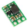
Pololu 12V Step-Up Voltage Regulator U3V12F12
Retired Product
Search for an alternative |

Overview
These boost (step-up) voltage regulators generate higher output voltages from input voltages as low as 2.5 V. They are switching regulators (also called switched-mode power supplies (SMPS) or DC-to-DC converters) and have a typical efficiency between 80% to 90%. The available output current is a function of the input voltage, output voltage, and efficiency (see Typical Efficiency and Output Current section below), but the input current can typically be as high as 1.4 A. This regulator is available with a fixed 5 V, 9 V, or 12 V output:
The regulator’s thermal shutdown prevents damage from overheating, but it does not have short-circuit or reverse-voltage protection.
 |
 |
Features
- input voltage: 2.5 V – VOUT
- fixed 5 V, 9 V, or 12 V output with 4% accuracy
- 1.4 A switch allows for input currents up to 1.4 A
- 2 mA typical no-load quiescent current
- integrated over-temperature shutoff
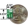
- small size: 0.515″ × 0.32″ × 0.1″ (13 × 8 × 3 mm)
Using the Regulator
Connections
The boost regulator has three connections: input voltage (VIN), ground (GND), and output voltage (VOUT).
The input voltage, VIN, must be at least 2.5 V and should not exceed the output voltage, VOUT. Please be wary of destructive LC spikes that might cause the input voltage to exceed VOUT (see below for more information).
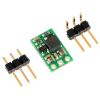
The three connections are labeled on the back side of the PCB, and they are arranged with a 0.1″ spacing along the edge of the board for compatibility with solderless breadboards, connectors, and other prototyping arrangements that use a 0.1″ grid. You can solder wires directly to the board or solder in either the 3×1 straight male header strip or the 3×1 right-angle male header strip that is included.
 |
Typical Efficiency and Output Current
The efficiency of a voltage regulator, defined as (Power out)/(Power in), is an important measure of its performance, especially when battery life or heat are concerns. As shown in the graphs below, this switching regulator typically has an efficiency of 80 to 90%.
 |
 |
 |
The maximum achievable output current is approximately proportional to the ratio of the input voltage to the output voltage. If the input current exceeds the switch current limit (typically somewhere between 1.4 and 2 A), the output voltage will begin to drop. Additionally, the maximum output current can depend on other factors, including the ambient temperature, air flow, and heat sinking.
LC Voltage Spikes
When connecting voltage to electronic circuits, the initial rush of current can cause damaging voltage spikes that are much higher than the input voltage. In Pololu's tests with typical power leads (~30″ test clips), input voltages above 10 V caused voltage spikes in excess of 20 V. You can suppress such spikes by soldering a 33μF or larger electrolytic capacitor close to the regulator between VIN and GND.
More information about LC spikes can be found in Pololu's application note, Understanding Destructive LC Voltage Spikes.
Exact shipping can be calculated on the view cart page (no login required).
Products that weigh more than 0.5 KG may cost more than what's shown (for example, test equipment, machines, >500mL liquids, etc).
We deliver Australia-wide with these options (depends on the final destination - you can get a quote on the view cart page):
- $3+ for Stamped Mail (typically 10+ business days, not tracked, only available on selected small items)
- $7+ for Standard Post (typically 6+ business days, tracked)
- $11+ for Express Post (typically 2+ business days, tracked)
- Pickup - Free! Only available to customers who live in the Newcastle region (must order online and only pickup after we email to notify you the order is ready). Orders placed after 2PM may not be ready until the following business day.
Non-metro addresses in WA, NT, SA & TAS can take 2+ days in addition to the above information.
Some batteries (such as LiPo) can't be shipped by Air. During checkout, Express Post and International Methods will not be an option if you have that type of battery in your shopping cart.
International Orders - the following rates are for New Zealand and will vary for other countries:
- $12+ for Pack and Track (3+ days, tracked)
- $16+ for Express International (2-5 days, tracked)
If you order lots of gear, the postage amount will increase based on the weight of your order.
Our physical address (here's a PDF which includes other key business details):
40 Aruma Place
Cardiff
NSW, 2285
Australia
Take a look at our customer service page if you have other questions such as "do we do purchase orders" (yes!) or "are prices GST inclusive" (yes they are!). We're here to help - get in touch with us to talk shop.
Have a product question? We're here to help!
Guides

The Maker Revolution
Projects
")
Raspberry Pi Cyberdeck (SDR Edition)

Pico-Dog Motion Activated Audio Alarm

WaveJumper: Music Sample Slicer on a Breadboard

Makers love reviews as much as you do, please follow this link to review the products you have purchased.
Product Comments