Hello makers, if you love to prototype circuits and create electronic designs, then you’ll be familiar with the humble solderless breadboard. It’s where most electronic projects begin and is a familiar sight for tinkerers and inventors. However, for a lot of people, getting started with breadboarding can be a confusing step, and understandably so; it’s not the way that you’re used to thinking about circuits. So today we’re going to take a look at everything to do with prototyping and using breadboards. If you’re interested in other prototyping techniques or would like to know more about prototyping a circuit in general, check out our Prototyping a Circuit tutorial. However, let’s crack on and take a look at how breadboards work, and whether or not you should use them for your project.
How Do They Work?
A breadboard is a very simple, yet useful piece of gear. Its name originates from times when circuit prototypes would be made using a wooden board (typically used for cutting bread), and nails/tacks hammered into solder to. This method has evolved into what we have today which is the solderless breadboard.
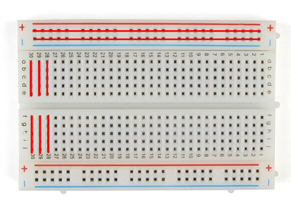
A typical breadboard consists of a 0.1” spaced grid of holes in which you can place component leads (0.1”/2.54mm is the most common standard for through-hole components). Inside each hole is a spring-loaded metal contact which grabs the wire/lead and strips of these holes are connected together to allow components to be connected together. Almost every breadboard will have numbered rows of 5 holes which are connected together, and every row is electrically isolated. Many also have power rail strips on the outside where all the holes in the rail are connected which makes it easy to power your circuit. Check out the diagram below to see which pins are connected.
Breadboards feature a divider down the middle of two spaces, to separate the rows, and allow Dual In-Line packages ICs to be mounted across the divider, which makes standard through-hole prototyping fairly easy.
The best way to connect points together is using jumper wires. These are insulated wires which rigid pins on the end designed to create a secure connection to the breadboard pin. Long flexible jumper wires are great for general connections, while smaller, rigid jumper wires can be used for low profile, fixed connections. Our favourite jumper wires are the DFRobot High-Quality Jumper wires which are the best possible quality wires available, and the Sparkfun Jumper Wire Kit, which contains a bunch of different sized pre-formed, solid core, insulated wires all organised into a divider organiser.
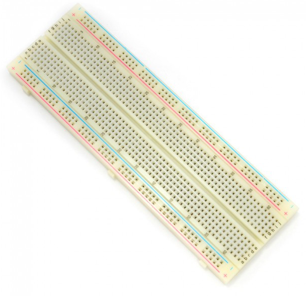
Speaking of connections, breadboards are generally categorized by the number of connection points, or tie points that they have. For example, a full-size breadboard will have 740 or 830 tie points on it, whereas a miniature breadboard will only have 170.
Something to be aware of is that on some breadboards, the power rails are separated in the middle to avoid inductance issues. Normally it is denoted by a break in the coloured line of the rail, and an extra space between the holes, however before diving into using one, it always pays to double check the connection with a multimeter.
If you’re looking at powering your breadboard projects, then look no further than our tutorial on Breadboard Power Supplies.
Pros and Cons of Using Breadboards
So this solderless prototyping system sounds great and all, but what are some of the advantages and disadvantages of using it to prototype your circuits?
Pros:
- Solderless connections make breadboards reusable, and easier to use for people who don’t have any soldering experience.
- The female/male notches on the side allow you to clip multiple breadboards together to create a much larger working area.
- Circuits can be easily modified.
- Quick and easy.
Cons:
- Breadboards are usually only rated for approximately 5W (5V at 1A)
- Connection strips can introduce extra resistance into circuits.
- Breadboards are unsuitable for high-frequency circuits due to the relatively large capacitance (around 5pF) between isolated pins.
- Temporary nature of breadboards means that jumper wires can easily come loose and make debugging difficult.
- Only Dual In-Line packages (DIP) can be used across the center divider due to spacing restrictions. SMD packages and other complex packages require breakout boards in order to be used with breadboards.
This is a bit of a bonus mention because it’s such a great product, but if you’re looking to transfer your temporary breadboard design to a more stable prototype, then check out these awesome Adafruit Perma-Proto boards which retain the layout and form factor of a breadboard, but instead of terminal pins, offer solder pads for a more durable prototype.
But anyway, that is our guide on using breadboards, how to use them, and whether they're going to be the right choice for your project. Check out some of our other prototyping tutorials, and get making!

