I SPI with my Raspberry Pi, something beginning with…S! Serial-Peripheral-Interface (SPI)! Welcome to our Raspberry Pi SPI communication tutorial. Today we’re going to look at how to use the SPI bus on our Raspberry Pi to communicate with SPI enabled devices.
SPI?
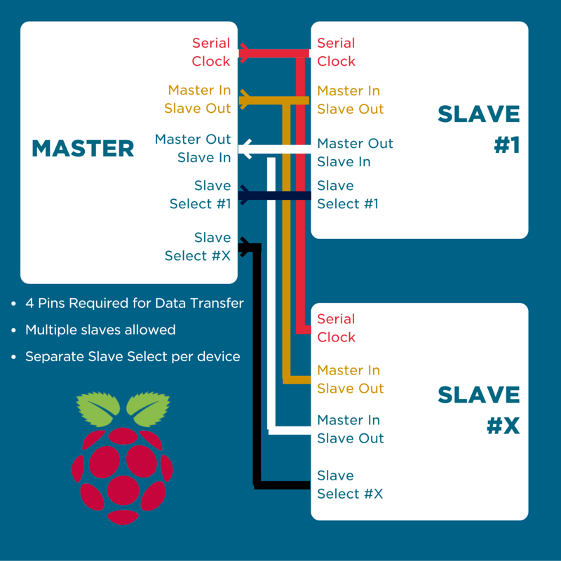
SPI is a synchronous serial communication protocol developed by Motorola for communication in embedded systems over a short distance between a single master device, and multiple slave devices. SPI is a cousin of the I2C communication protocol (check out our I2C with Raspberry Pi tutorial), however it is a faster method of communication than I2C, with the drawback of needing a Chip Select wire for every slave device on the bus.
Like in our I2C tutorial, take a look at the SPI and the Arduino tutorial which covers the ins and outs of SPI communication in a general sense, before moving into Arduino specific content.
As fun and all as today’s High Defintion displays and graphical displays are, it can often by quite useful to display information or graphics on a dot matrix display. You could make a snake game, a simple side scroller, tetris, and many other applications.
Today, we’re going to be looking at using the Sparkfun SPI 8x8 Red/Green LED Matrix which uses SPI to interface with a controller device. This gives us a 64 LED grid to use with 4 different colour options per LED: off, Red, Green, and Yellow (Red Green).
The Gear
To follow this tutorial you will require the following components:
- Raspbrry Pi 3e
- Sparkfun SPI 8x8 LED Matrix (this product has now been retired from Sparkfun, however all the functionality in this article can be transferred to any other SPI device)
- Male-Male Jumper Wires
- Female-Male Jumper Wires
- Logic Level Converter
- Breadboard
Along with this things, you will need everything required to use the Pi 3 board such as a power supply, display etc… for more info on this, check out our Getting Started with Raspberry Pitutorial. As always, we strongly recommend using the Pimoroni Pibow Coupe case. The hardware access and pin labelling will change your life
The Goal
We’re going to use the SPI bus on the Raspberry Pi to create an LED sequence on the LED matrix. Once you understand how to control the LEDs on the matrix, you can write a program to do whatever you want it to do.
Even though another SPI device might operate differently and require different data to be sent to it, it still remains within the structure of SPI communication, which means once you understand how to send/receive data on the SPI bus, you can control any device as per its datasheet. The datasheet for the Sparkfun LED matrix can be found here.
Raspberry Pi Board Setup
Before we do anything though, we need to do a few things to setup our Raspberry Pi board to work with the SPI interface. The first thing to do is make sure that Raspbian is updated to the latest version. To do this, open a new Terminal window and type:
sudo apt-get update
And after the update is completed:
sudo apt-get upgrade
Awesome, now you Raspberry Pi will have all of the latest packages available to use. Now we need to enable the SPI interface on our board. To do this, go to the Menu -> Preferences -> Raspberry Pi Configuration, then under the ‘Interfaces’ tab, select SPI as ‘enabled’, and then reboot.
All the tools and python libraries required to use the SPI bus are now included in the latest build of Raspbian, so we don’t need to worry about downloading any external packages.
Your Pi should now be setup to use the SPI interface in Python.
Communicating with the LED Matrix Backpack
By reading through the datasheet for the backpack (backpack is the term for the controller board built on the back of the LED grid), we can see that controlling the LEDs is quite simple.
Each LED can be controlled by sending a byte to the backpack sequentially (one after the other) along the MOSI line on the SPI bus. It maintains a 64 byte buffer which means that the last 64 bytes to be sent to it are stored in the buffer. The backpack will accept the input when the chip select is asserted (held low for the device). In this time, the first byte you send to it will control the first LED, the second byte will control the second LED and so on. As per SPI protocol, the backpack will send the old buffer data back to the master device via the MISO line on the SPI bus.
Therefore if we want to control all 64 LEDs at once, we need to send a packet of 64 bytes sequentially to the backpack board, with the value of each byte determining the colour of the corresponding LED.
As specified in the datasheet, the colour for each LED can be set as follows:
- Off: 0x00
- Green: 0x01
- Red: 0x02
- Green Red (Yellow): 0x03
*Note that the SPI dev module is taking care of all the timing and nitty-gritty details required to send data on an SPI bus, this allows us to only focus on the data we’re sending*
 The Circuit
 The Circuit
As always, make sure that you’re Raspberry Pi is unplugged from power before connecting anything up to the GPIO pins, this reduces the risk of accidentally shorting something and potentially damaging a pin, or the whole board.
The only issue with our board (they might have fixed it in a later revision, however this backpack is at the end of its life cycle, so maybe not) is that the connectors on either side seem to be counter intuitively named. One set of headers is marked as SPI Output, and the other as SPI Input, however the MOSI pin which is the Master Output, is on the input side.
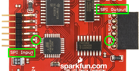
We confirmed the MOSI and MISO pins to be labelled correctly, so just be aware that the SPI Output headers are where you’ll actually plug all the input wires into. Logic huh? This kind of makes sense when you are daisy chaining multiple backpacks, however as long as you match up the colours of the wires as per our diagram, everything should be fine.
The issue with this backpack is that it operates at 5V which makes it troublesome to connect up to our Raspberry Pi, which operates all its GPIO pins including the SPI bus at 3.3V. Never fear though, that’s why we’ve got the logic level converter on there. It is bi-directional which means we could also use it to step down 5V logic signals to 3.3V, very handy to have in your inventor’s tool kit.
The Code
The code below is designed to light the LEDs up sequentially, then turn them all off in the same order. This is accomplished by creating a list and populating it/wiping it then sending that list on the SPI bus each time we make a change. The beauty of the 64 byte buffer on the backpack is that if we only send one byte to it in a block, it will only write to the first LED and will not change the rest of the LED bytes. Thus we can create our sequence by adding a new colour byte to the list, sending it, and repeat. At the end of each cycle, we change the colour.
Write it into your Python3 editor and go Run -> Run Module to run the program inside the Python shell. Make sure that you use Python3 as there might be unexpected results in the older environment due to structural changes.
#import modules
import spidev
import time

#initialise SPIDev
spi=spidev.SpiDev()
spi.open(0,0)
spi.max_speed_hz = 125000
time.sleep(0.0005)

#create our list to send on the SPI bus
to_send = []

#initialise variables
colour = 0x01
delay = 0.05

#set all LEDs to off
for i in range (0, 64):
    to_send.append(0x00)
    spi.xfer(to_send)

time.sleep(0.0005)  #delay for stability

#main loop
try:
    while 1:

        #if to_send list contains less than 64 values, add another byte to the list
        if to_send.count(colour) < 64:
            del to_send[:]
            for i in range(0,64):
                to_send.append(colour)
                spi.xfer(to_send)
                time.sleep(delay)

        #if the list is full (64 items), reset the list and replace each value with 0x00
        if to_send.count(colour) == 64:
            del to_send[:]
            for i in range(0, 64):
                to_send.append(0x00)
                spi.xfer(to_send)
                time.sleep(delay)

        colour = colour   0x01  #cycle through the available colours

        if colour == 0x04:  #when the last colour is reached, reset to 0x01
            colour = 0x01

except KeyboardInterrupt:   #if Ctrl   C is pressed, cleanly exit our program
    for i in range (0, 64):
        to_send.append(0x00)
    spi.xfer(to_send)
    spi.close()
    print("Program Exited")
The key to the way this program operates is the two different methods of data transfer that can be used with the SPI dev module.
Xfer2 will send data on the MOSI line, and keep the CS active between blocks, however the Xfer function will send data on the MOSI line and reset the CS line between each block. This means that when we are sending less than 64 bytes, it still counts as a complete transfer and only writes as many LEDs as bytes that we transferred.
Something to bear in mind is that the SPI protocol dictates that for as many bytes as you send from the master, the slave will output that many bytes back on the MISO line. The backpack datasheet states that it outputs the previous contents of the buffer each time it is refreshed. If we wanted to get feedback from the matrix, we could use the read function to read this data, but for this simple application, it isn’t needed, so we ignore it. For all of the available functions in the SPI dev module, check out the documentation here.
What Now?
Whilst we focused on working specifically with the Sparkfun LED matrix backpack, the functions and tools that we learnt about in the SPI dev module can be used to control any SPI device. The datasheet for each device should specify how it should be controlled within the SPI framework, and you can adapt your program accordingly. Check out our other tutorials and projects for inspiration for your next project, and feel free to let us know if you have any trouble.

