 I²C stands for the inter-integrated circuit and refers to a communication protocol we are going to use to communicate between our Arduino devices. In the past we have investigated the SPI and Asynchronous Serial Communications protocols for this purpose, check them out before we delve into the new topic of I²C communications.
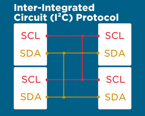
I²C uses 2 signals for transferring data between devices, this halves the SPI’s 4 wire communication protocol. The signals we will use are called:
- Data signal (SDA) – This is where all of our control information and data is sent/received. Everything is sent on this signal and can be sent anywhere on the bus.
- A clock signal (SCL) – This is purely for regulating the speed the data is sent. The slave devices will sample a bit from the data stream in synchronization with this signal.
Devices that use I²C are “open drain” on the data signal. This means that they are only able to pull the line low, eliminating the risk of bus contention which can damage components. Every signal line has an internal pull-up resistor that drive the line back to high when a device is using it.
I²C is a multi-master system, meaning you can have more than one master controlling data being sent on the bus. The bus refers to the family of integrated circuits we are communicating between and the limit for how many devices can ‘be on’ one bus is 1008.
So how do we differentiate between our 1008 devices? We give them all a unique 7-bit address. With each device that uses I2C on the same bus needing an address.
We start the communications on our bus by sending the data line low and holding the clock signal high. This alerts all devices on the bus that we are about to begin communications. We send the address byte after our start condition the first 7 bits is the address with the final bit being a read/write bit.
The slave device then sends back an Acknowledge bit, letting the master know it is on the bus and ready for communications. After the ACK bit, the master begins sending data 1 byte at a time and waits for the acknowledge bit from the slave.
When the master is finished sending the data, it will set the clock line high and reset the data line to high. This effectively ends data transfer on the bus.

Why use I2C?
- Far easier to use than SPI.
- Uses fewer connections than SPI.
- Supports a multi-master system, rather than SPI’s one master, infinite-slaves system.
- 100% compatible with our Arduino Uno.
The Project
If you remember the SPI tutorial, we controlled 8 LEDs with an 8-Pin Shift Register using SPI principles. Today we will be using I²C to build upon that same design, this time controlling 16 LEDs with a 28 Pin Input/output expander called the MCP23017.
We will add the concept of a simple 8-bit binary counter, making our I²C device control a 16-bit binary counter with 16 LEDs, each representing one bit on the counter.
Components needed:
- 1 x Arduino Uno board
- 1 x Solderless breadboard
- 1 x MCP23017
- 27 x Jumper wires
- 16 x LEDs
- 16 x 220 Ω Resistor
- 2 x 4.7K Ω Resistor
Software needed:
- Wire.h library
- Arduino IDE
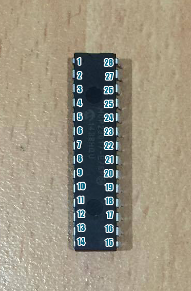
The MCP23017 IC package
The MCP is a 28 Pin, DIP IC that we are going to use as a slave in our LED circuit. If you google for the datasheet of the part and search through it, you will find that the MCP allows us to set the last 3 bits of its 7-bit address (see pins 15-17 in Fritzing Sketch). The first four being set to 0100.

The only relevant Arduino Pins in this project are:
- Pin A4 = SDA
- Pin A5 = SCL
This table represents what each leg of the IC we are using is for. The legs of the IC are labeled as follows: Pin 1 is left of indent on the top of IC, pin 14 is the bottom left pin, pin 15 in the bottom right pin and pin 24 is the top right pin. This convention of increasing counter-clockwise will be the same for all DIP ICs we use. That’s almost everything we need to get started with our circuit. Let’s connect it all up!
The Setup
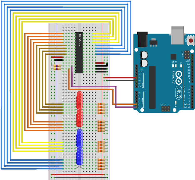
- Connect your MCP23017 to the center of your breadboard over the vertical break, orient the chip such that Pin 1 is at the top left and Pin 24 is at the top right.
- Connect your 16 LEDs and resistors in series on separate lines.
- Connect 5v and GND from the Arduino to the breadboard as shown.
- Connect the MCP23017 to the Arduino according to both the sketch (left) and the table above.
- Use a jumper wire to connect pin 10, 15, 16 and 17 of the MCP to the GND rails. Pin 10 is ground for the IC. 15, 16 and 17 are hardware address pins that we are going to set to 0.
- Use a jumper wire to connect pin 9 and 18 to the 5v rail. Pin 9 is Vcc for the IC and pin 10 is the reset pin, so tying it to Vcc means we will never reset the transfer.
- Finally, connect the LED array in the way shown.
The Code
#include <wire.h>
int counter = 0;
void setup()
{
  Wire.begin();                 // wake up I2C bus

  // set I/O pins to outputs

  Wire.beginTransmission(0x20);
  Wire.write(0x00);             // IODIRA register
  Wire.write(0x00);             // set all of port A to outputs
  Wire.endTransmission();
  Wire.beginTransmission(0x20);
  Wire.write(0x01);             // IODIRB register
  Wire.write(0x00);             // set all of port B to outputs
  Wire.endTransmission();
}
void binaryCount()
{
 counter=counter 1;             //add 1 to counter variable initialised as 0 above
}
void updateLEDs()
{
  byte porta = counter;         // send bits 0..7 of 'counter' to porta
  byte portb = counter >> 8;    // send bits 8..15 of 'counter' to portb

  Wire.beginTransmission(0x20); //Start sending to GPA LEDs
  Wire.write(0x12); // GPIOA    //Writing to GPA0-GPA7
  Wire.write(porta); // port A  //Writing bits 8-15 of counter to these pins, Least Significant Bit first
  Wire.endTransmission();       //End sending to GPA LEDs
  Wire.beginTransmission(0x20); //Start sending to GPA LEDs
  Wire.write(0x13);             //Writing to GPB0-GPB7
  Wire.write(portb);            //Writing bits 0-7 of counter to these pins, Least Significant Bit first
  Wire.endTransmission();       //End sending to GPB LEDs
}
void delayTime()
{
 delay(1);                      //Delay time in ms between GPA_LED updates
}

void loop()
{
  binaryCount();                //Increases counter by one each iteration
  updateLEDs();                 //Changes LEDs to represent "counter's" value
  delayTime();                  //Sets a speed to the counter
}
Upload the code to your board, if you want a more thorough understanding of the coding process read through the comments within the code.
Remember how I mentioned this was going to be similar to our SPI project? Set your delay to <50 to see the counter get through the first 8 bits nice and fast. What you should see after that is port A begin to light up in the same sequence. We have extended our counter a 16-bit binary counter!
Congratulations, you have just used the wire.h library to configure and communicate between 2 devices on the I2C protocol

