
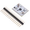


STSPIN220 Low-Voltage Stepper Motor Driver Carrier
Available with a lead time
Expect dispatch between Jul 22 and Jul 27
Quantity Discounts:
- 10+ $16.05 (exc GST)
- 25+ $15.55 (exc GST)
 |
STSPIN220 Low-Voltage Stepper Motor Driver Carrier, bottom view with dimensions. |
|---|
This product is a carrier board or breakout board for the STSPIN220 low-voltage stepper motor driver from STMicroelectronics (ST); Pololu therefore recommend careful reading of the STSPIN220 datasheet (1MB pdf) before using this product. This stepper motor driver offers microstep resolutions down to 1/256 of a step, and it lets you control one bipolar stepper motor at up to approximately 1.1 A per phase continuously without a heat sink or forced air flow (see the Power dissipation considerations section below for more information). Here are some of the driver’s key features:
- Simple step and direction control interface
- Nine different step resolutions down to 256 microsteps: full-step, half-step, 1/4-step, 1/8-step, 1/16-step, 1/32-step, 1/64-step, 1/128-step, and 1/256-step
- Adjustable current control lets you set the maximum current output, which lets you use voltages above your stepper motor’s rated voltage to achieve higher step rates
- Motor supply voltage: 1.8 V to 10 V (for a higher-voltage alternative, consider the STSPIN820 carrier, which operates from 7 V to 45 V)
- Can deliver 1.1 A per phase continuously without additional cooling
- Can interface directly with 3.3 V and 5 V systems
- Over-temperature thermal shutdown, over-current shutdown, and short circuit protection
- 4-layer, 2 oz copper PCB for improved heat dissipation
- Exposed solderable ground pad below the driver IC on the bottom of the PCB
- Module size, pinout, and interface match those of Pololu's A4988 stepper motor driver carriers in most respects
This product ships with all surface-mount components—including the STSPIN220 driver IC—installed as shown in the product picture.
 |
Included hardware
The STSPIN220 low-voltage stepper motor driver carrier ships with one 1×16-pin breakaway 0.1" male headers (for a version of this carrier with header pins already installed, see item #2877). The headers can be soldered in for use with solderless breadboards or 0.1" female connectors. You can also solder your motor leads and other connections directly to the board.
|
|


Using the driver
 |
Minimal wiring diagram for connecting a microcontroller to a STSPIN220 low-voltage stepper motor driver carrier. |
|---|
Power connections
The driver requires a logic supply voltage (3 – 5 V) to be connected across the VCC and GND pins and a motor supply voltage of 1.8 V to 10 V to be connected across VIN and GND. These supplies should have appropriate decoupling capacitors close to the board, and they should be capable of delivering the expected currents (peaks up to 3 A for the motor supply).
Motor connections
The STSPIN220 is intended to control a single bipolar stepper motor. The two sides of one coil should be connected across OUTA1 and OUTA2, and the two sides of the other coil should be connected across OUTB1 and OUTB2.
Warning: Connecting or disconnecting a stepper motor while the driver is powered can destroy the driver. (More generally, rewiring anything while it is powered is asking for trouble.)
Step (and microstep) size
Stepper motors typically have a step size specification (e.g. 1.8° or 200 steps per revolution), which applies to full steps. A microstepping driver such as the STSPIN220 allows higher resolutions by allowing intermediate step locations, which are achieved by energizing the coils with intermediate current levels. For instance, driving a motor in quarter-step mode will give the 200-step-per-revolution motor 800 microsteps per revolution by using four different current levels.
Unlike Pololu's other stepper motor drivers, some of the resolution (step size) selector inputs share pins with the STEP/STCK and DIR pins, and the values of the inputs are latched at power-up or when standby mode is released. After this, the values on the inputs do not affect the microstep mode, and the MODE3 and MODE4 inputs start operating as step and direction controls. The only exception is the case where MODE1 and MODE2 are both driven low, which overrides the latched microstep setting and forces the driver into full-step mode. The previous microstep setting is restored once MODE1 or MODE2 is set high.
There are nine step resolutions available as shown in the table below. The four MODE pins are floating, so Pololu must be connected to logic high or low before operating the driver. For the microstep modes to function correctly, the current limit must be set low enough (see below) so that current limiting gets engaged. Otherwise, the intermediate current levels will not be correctly maintained, and the motor will skip microsteps.
| MODE1 | MODE2 | MODE3 (STEP) | MODE4 (DIR) | Latched step setting |
|---|---|---|---|---|
| Low | Low | Low | Low | Full step |
| High | Low | High | Low | Half step |
| Low | High | Low | High | 1/4 step |
| High | High | High | Low | 1/8 step |
| High | Low | High | High | 1/8 step |
| High | High | High | High | 1/16 step |
| Low | High | Low | Low | 1/32 step |
| Low | Low | Low | High | 1/32 step(1) |
| High | High | Low | High | 1/64step |
| Low | High | High | High | 1/64 step |
| High | Low | Low | Low | 1/128 step |
| Low | Low | High | Low | 1/128 step(1) |
| High | High | Low | Low | 1/256 step |
| Low | High | High | Low | 1/256 step |
| High | Low | Low | High | 1/256 step |
| Low | Low | High | High | 1/256 step(1) |
1 Keeping the MODE1 and MODE2 inputs low after the step resolution configuration forces the driver into full-step mode instead of the selected configuration.
Control inputs and status outputs
The rising edge of each pulse to the STEP (STCK) input corresponds to one microstep of the stepper motor in the direction selected by the DIR pin. Unlike most of Pololu's other stepper motor driver carriers, the STEP and DIR inputs are floating, so Pololu must be connected to logic high or low to ensure proper operation.
The STSPIN220 IC has two different inputs for controlling its power states, STBY/RESET and EN/FAULT:
- When the STBY pin is driven low, the driver enters a low-power mode, disables the motor outputs, and resets the translation table. Pololu call this pin STBY on Pololu's board based on the logic of how it works, but it is a direct connection to the STBY pin on the driver. The board pulls this pin high by default.
- The EN pin is inverted by Pololu's carrier board and presented as ENABLE, which makes it the same way as the enable pins on Pololu's various other stepper motor drivers with this form factor. It is pulled low on the board to enable the driver by default, and it can be driven high to disable the outputs.
The STSPIN220 can detect several fault (error) states that it reports by driving its EN/FAULT pin low. The FAULT pin is not made available by default (to avoid conflicts when using the STSPIN220 carrier as a drop-in replacement for Pololu's other stepper motor driver carriers), but it can be connected to the pin labeled “(1)” or “(2)” by bridging the surface mount jumper labeled “F” on the bottom side of the board to the corresponding pad labeled “1” or “2”.
 |
Jumpers for FLT and VREF pins on the STSPIN220 low-voltage stepper driver carrier. |
|---|
Current limiting
To achieve high step rates, the motor supply is typically higher than would be permissible without active current limiting. For instance, a typical stepper motor might have a maximum current rating of 1 A with a 5 O coil resistance, which would indicate a maximum motor supply of 5 V. Using such a motor with 10 V would allow higher step rates, but the current must actively be limited to under 1 A to prevent damage to the motor.
The STSPIN220 supports such active current limiting, and the trimmer potentiometer on the board can be used to set the current limit. You will typically want to set the driver’s current limit to be at or below the current rating of your stepper motor. One way to set the current limit is to put the driver into full-step mode and to measure the current running through a single motor coil without clocking the STEP input. The measured current will be equal to the current limit (since both coils are always on and limited to 100% of the current limit setting in full-step mode).
Another way to set the current limit is to measure the VREF voltage and calculate the resulting current limit. The VREF pin voltage is accessible via a small hole that is circled on the bottom silkscreen of the circuit board. The current limit in Amps relates to the reference voltage in Volts as follows:
or, rearranged to solve for VREF:
Like the FAULT pin, VREF can be connected to the pin labeled “(1)” or “(2)” by bridging the surface mount jumper labeled “R” on the bottom side of the board to the corresponding pad labeled “1” or “2”.
Note: The coil current can be very different from the power supply current, so you should not use the current measured at the power supply to set the current limit. The appropriate place to put your current meter is in series with one of your stepper motor coils. If the driver is in full-step mode, both coils will always be on and limited to 100% of the current limit setting as (unlike some other drivers that limit it to about 70% in full-step mode). If your driver is in one of the microstepping modes, the current through the coils will change with each step, ranging from 0% to 100% of the set limit.
Power dissipation considerations
The driver ICs have maximum current ratings higher than the continuous currents Pololu specify for these carrier boards, but the actual current you can deliver depends on how well you can keep the IC cool. The carrier’s printed circuit board is designed to draw heat out of the IC, but to supply more than the specified continuous current per coil, a heat sink or other cooling method is required.
This product can get hot enough to burn you long before the chip overheats. Take care when handling this product and other components connected to it.
Please note that measuring the current draw at the power supply will generally not provide an accurate measure of the coil current. Since the input voltage to the driver can be significantly higher than the coil voltage, the measured current on the power supply can be quite a bit lower than the coil current (the driver and coil basically act like a switching step-down power supply). Also, if the supply voltage is very high compared to what the motor needs to achieve the set current, the duty cycle will be very low, which also leads to significant differences between average and RMS currents. Additionally, please note that the coil current is a function of the set current limit, but it does not necessarily equal the current limit setting as the actual current through each coil changes with each microstep and can be further reduced if Active Gain Control is active.
Schematic diagram
 |
Schematic diagram of the STSPIN220 Low-Voltage Stepper Motor Driver Carrier. |
|---|
This schematic is also available as a downloadable pdf (111k pdf).
People often buy this product together with:
 | Stepper Motor: Bipolar, 200 Steps/Rev, 20×30mm, 3.9V, 0.6 A/Phase |
 | DRV8834 Low-Voltage Stepper Motor Driver Carrier |
 | STSPIN820 Stepper Motor Driver Carrier |
Dimensions
| Size: | 0.6" × 0.8" |
|---|---|
| Weight: | 1.4 g1 |
General specifications
| Motor driver: | STSPIN220 |
|---|---|
| Minimum operating voltage: | 1.8 V |
| Maximum operating voltage: | 10 V |
| Continuous current per phase: | 1.1 A |
| Maximum current per phase: | 1.3 A |
| Minimum logic voltage: | 1.6 V |
| Maximum logic voltage: | 5.5 V |
| Microstep resolutions: | full, 1/2, 1/4, 1/8, 1/16, 1/32, 1/64, 1/128, 1/256 |
| Current limit control: | potentiometer |
| Reverse voltage protection?: | N |
| Header pins soldered?: | N |
Identifying markings
| PCB dev codes: | md39a |
|---|---|
| Other PCB markings: | 0J11899 |
Notes:
File downloads
-
STSPIN220 datasheet (1MB pdf)
-
Schematic diagram of the STSPIN220 Stepper Motor Driver Carrier (111k pdf)
-
Dimension diagram of the STSPIN220 Stepper Motor Driver Carrier (326k pdf)
-
3D model of the STSPIN220 Stepper Motor Driver Carrier (5MB step)
-
Drill guide for the STSPIN220 Stepper Motor Driver Carrier (37k dxf)
This DXF drawing shows the locations of all of the board’s holes.
-
AN4923 application note for the STSPIN220: step-mode selection and on-the-fly switching to full-step (414k pdf)
The STSPIN220’s integrated sequencer can provide a resolution up to 256 microsteps, but it is always possible to switch to the full-step operation on-the-fly. This document describes how to select the step resolution and manage the switch between the microstep and full-step operation.
Recommended links
-
STSPIN220 documentation and resources
STMicro’s product page for the STSPIN220 low-voltage stepper motor driver, with links to its most up-to-date datasheet and other resources.
Exact shipping can be calculated on the view cart page (no login required).
Products that weigh more than 0.5 KG may cost more than what's shown (for example, test equipment, machines, >500mL liquids, etc).
We deliver Australia-wide with these options (depends on the final destination - you can get a quote on the view cart page):
- $3+ for Stamped Mail (typically 10+ business days, not tracked, only available on selected small items)
- $7+ for Standard Post (typically 6+ business days, tracked)
- $11+ for Express Post (typically 2+ business days, tracked)
- Pickup - Free! Only available to customers who live in the Newcastle region (must order online and only pickup after we email to notify you the order is ready). Orders placed after 2PM may not be ready until the following business day.
Non-metro addresses in WA, NT, SA & TAS can take 2+ days in addition to the above information.
Some batteries (such as LiPo) can't be shipped by Air. During checkout, Express Post and International Methods will not be an option if you have that type of battery in your shopping cart.
International Orders - the following rates are for New Zealand and will vary for other countries:
- $12+ for Pack and Track (3+ days, tracked)
- $16+ for Express International (2-5 days, tracked)
If you order lots of gear, the postage amount will increase based on the weight of your order.
Our physical address (here's a PDF which includes other key business details):
40 Aruma Place
Cardiff
NSW, 2285
Australia
Take a look at our customer service page if you have other questions such as "do we do purchase orders" (yes!) or "are prices GST inclusive" (yes they are!). We're here to help - get in touch with us to talk shop.
Have a product question? We're here to help!
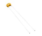
 22pF Ceramic Disc CapacitorSKU: CE05189 Brand: Core Electronics50V Voltage Rating, 5% Tolerance. Single pitch lead spacing.
-
-
-

Guides

The Maker Revolution
Projects

The Rats Nest VCC Desktop Power Supply

Remote-Controlled Mars Rover

FlipperMate: Hands-Free Pinball

Makers love reviews as much as you do, please follow this link to review the products you have purchased.
Product Comments