Introduction
This project started because I needed to replace a water tap timer that had seen better days.
The aim was to use a Raspberry Pi Pico and a couple of PiicoDev boards to do what the water timer did. The actual stopping and starting of the water could be done with a watering system solenoid and is not covered here.
 |
 |
 |
Operation
One switch cycles through the timing intervals, which are displayed on a screen.
Another switch activates/deactivates the timer.
Timing intervals are 30, 60, 90, and 120 minutes with an always ON mode.
The screen shows the number of minutes left to count down when timing.
The project is battery-powered and has a sleep mode.
The output is a relay contact to control power to an external device.
The program is written in Micropython, easy to program and has excellent PiicoDev libraries.
Parts:
- Raspberry Pi Pico SKU: CE07564
- PiicoDev Capacitive Touch Sensor SKU: CE07816
- PiicoDev OLED Display Module (128x64) SSD1306 SKU: CE07911
- Pololu Basic SPDT Relay Carrier with 5VDC Relay (Assembled) SKU: POLOLU-248
- Two AAA Battery Holders for 2 x AAA NiMH 900mAH cells each.
- IP65 Sealed Polycarbonate Enclosure with Mounting Flange - 115(W) x 65(D) x 40(H)mm CAT.NO: HB6249
 |
 |
 |
 |
 |
 |
Design
Basic Operation
Two CAP TOUCH sensors are used as the switches.
Device Inactive
- Sense 1 - cycles through timing options
- Sense 2 - activates the currently selected option and the relay turns on.
Device Active
- Sense 1 – no effect
- Sense 2 - stops the current timing and resets to no timing.
Device Sleep State
- Either Sense will wake it up.
Connection diagram
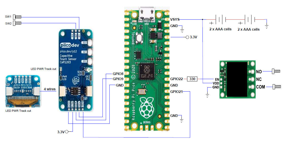
On Board LED
- Single flash on power up
- Timing activated - flashes at 100ms duty cycle
- Flashes 4 times when entering sleep mode
- Flashes once when leaving sleep mode
OLED
The built-in font included in the PiicoDev library is much too small for this project. The display will only show 3 numbers so the font needs to be much larger and scaling is not provided in the Piicodev library.
Graphics files were used as the easiest way to display the count down. Each file takes 1k to 3K of memory in the Pico. The display only shows 5 minute intervals to reduce the number of files. 24 .pbm files were created on a graphics editor. 5 through to 120 and ON.
Dormant Mode
The sleep function for the Pi Pico is called Dormant mode. There is a second mode which does not completely shutdown the Pico but it does not provide enough power saving. Dormant mode is entered when a 32 bit word is written to a register. Dormant mode is exited when an interrupt occurs. The interrupt must be set up before entering Dormant mode and the clocks must be set so the interrupt will work to wake the Pico. The interrupt function is provided by the INT output of the CAP TOUCH sensor connected to a GPIO pin.
During software development, the program would get lost when waking up if the resistor manipulation did not occur in the same def() statement. Initially multiple def() statements were used and the Pico would sometimes wake from sleep, sometimes not. Also, turning the phase locked loop clock PLL_SYS off caused the Pico not to wake correctly or not to wake at all. This clock is not altered by the program
Note: The Pico has a 12 MHz crystal but the system clock runs at 125 Mhz by using the PLL_SYS clock. When the system clock was set to 12MHz the Python script ran very slow and not correctly as things like the CAP TOUCH sense took too long to be acknowledged.
Switch, Relay Connections, and Case
The capacitive nature of the CAP TOUCH sensor makes it ideal for providing water and dust proof connections. Simply connect a sensor pad to a metal bolt protruding through the plastic case. The same has been done for the relay connections. If these bolts are mounted with rubber or silicone gaskets the IP65 rating of the case is maintained. All the electronics remain inside the case sealed against water and dust ingress. The clear cover allows easy display of what the device is doing.
Battery
Power is provided by 4 x AAA NiMH 900mAH cells resulting in a voltage range of about 4V to 5.6V. The Pico runs at 3.3V through a buck/boost regulator allowing a wide input voltage range. The relay was tested over this range and worked correctly. A disadvantage is the cover must be removed to replace or recharge the batteries; something to consider for future design.
Construction
Fitting all the parts into the small case was a challenge. Eventually a design was chosen and the parts mounted on a vero board; which was screwed to plastic standoffs inside the case. The vero board is slightly too short; the top connections for the CAP TOUCH sensor almost miss the board. Something to consider for future design.
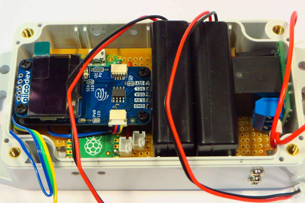
The relay is soldered to the board via 2 of its mounting holes and a short length of wire.
The Pico is soldered by short lengths of wire to the pins used by the circuit.
The battery connectors are staggered so the two battery packs are in series.
Some of the tracks on the vero board provide circuit connections.
As can be seen from the underside view there is not much soldering on the board.
 |
 |
 |
 |
Software:
The software on the Pico consists of the following files:
| main.py | Running Program |
| PiicoDev_CAP1203.py | CAP TOUCH library |
| PiicoDev_SSD1306.py | OLED library |
| PiicoDev_Unified.py | Unified library |
Note: When Micropython sees a file called main.py it runs the file on power-up.
The program loops through checking various states every 100ms. Nothing happens until a sensor button is touched. If NO button is touched for 5 minutes the program enters dormant mode and remains there until a button is pressed.
Countdown from 30 minutes.
 |
 |
 |
 |
Testing, Problem Solving:
OLED Graphics Files
The .pbm files, initially, did not load correctly and caused the program to crash. Yet the PiicoDev logo file provided with the library loaded perfectly. Examination of the created files and the PiicoDev logo file revealed a bug in the PiicoDev library. This has since been fixed by Core Electronics and the library now loads .pbm files created with any editor, correctly. The actual files created for this project were correct in the first place.
Power Consumption (ie battery life).
When not timing current consumption is about 20mA; when timing and displaying countdown about 25mA. The Relay draws about 75mA when activated, so total current draw is about 100mA.
When in sleep mode the current drain is 1.8mA.
Pico = 0.3mA,
CAP TOUCH sensor = 0.4mA,
OLED in power down mode = 1.1mA. (powered off mode)
It is disappointing that the OLED consumes so much when it is supposed to be powered off.
I think the power off function is turning the chip off, while the display still has power even though nothing is showing on it.
So in sleep mode the approximate battery life is about 20 days. Not the greatest.
In timing mode about 8 or 9 hours, probably less. Considering it is powering a relay, not too bad.
In other low power projects using an ATMEGA328P and 4 digit 7 segment display I have achieved around 0.35mA for the whole project in sleep mode; and Half of that is for the display. This would probably be the preferred solution for version 2 of this project. Using the Pico as a countdown timer is a waste of its ability.
Conclusion:
This project was really an investigation into a practical use for the Pi Pico. Being used only as a countdown timer is a waste of the Pico's abilities. This project could be expanded to control a complex watering system, it could have many sensors and control many solenoids. An algorithm could be developed to determine when to water and when not based on environmental sensors.
The choice of a battery for this project was to make it portable and standalone as a simple relay timer.
An important practical part of this project was getting the sleep mode of the Pico to work with Micropython. There was nothing that could produce 0.3mA in dormant mode in any of the libraries searched. The built-in functions in Micropython and Circuit Python did not achieve usable results. The one example on GitHub that seemed to work, did not. The Pico never left Dormant mode, it required a reset of the Pico.
The C SDK for the Pico worked (with some tweaks) but libraries for the PiicoDev CAP TOUCH and OLED sensors did not exist. Programming, loading and running code with the C SDK is not as smooth as Micropython and Thonny. But the resultant compiled machine instructions take up less memory than using the Micropython Interpreter. With more refining of the SDK and development of an IDE maybe this would be the path in the future. As a side note the Pico C SDK implementation using the Arduino IDE was examined, but not seen as a viable option for this simple project.
As a learning experience this was a great project, I explored many options and now have a good understanding of the Pico and the development options available. The project also identified a bug in the OLED PiicoDev library, which makes it more robust and mature.
Still having fun !!!
Attachments:

