This thermometer idea came to me when my little sister asked me “Vince, what’s the temperature?” Answering I said, “Well, I’ll look it up.” So I looked it up but that wasn’t enough for her, This continued for a few days. She then wanted the humidity as well as the temperature and so I decided to build this. A very basic, but effective ‘meter’ that can measure temperature and humidity with a refresh rate of 2 times per/second. It uses the DHT22 sensor for its accuracy and easy to use libraries.
Parts Required
-
1 x 10K Trimpot
-
1 x Breadboard
-
1 x Jumper wires M-M
- 1 x Arduino Pro Mini (5V Microcontroller)
-
1 x 9 Volt Battery
-
1 x Pushbutton latching(I chose red) or 1 x toggle switch
- 5 x M3 Hex Nuts
-
2 x M3 10mm bolts
-
2 x M3 14mm Bolts
- 1 x M3 7mm Bolt (Optional - you can use any other size above 7mm)
-
1 x 3D Printed case
The Build
Follow the Fritzing diagram below for the breadboard circuit.
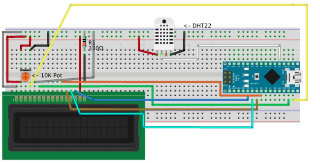
NOTE: You’ll notice in the Fritzing diagram that the DHT22 sensor has only 3 of the 4 leads connected to the circuit; this isn’t a mistake it is by design.
The Code and Library
You can download the code from my Github page.
You will also need to install one library called “ABlocks_DHT.h”. This library makes it easy to read the temperature and humidity without too much trouble. You can download this library from the link above.
Installing the Library
Once you have downloaded the library from the link you can go ahead and install it.
1. In the Arduino IDE (Integrated Development Environment) go to: Sketch> Include Library> Add .ZIP Library…
2. Click on the “Add .ZIP Library…” Button
3. This should bring up a menu saying to add a ZIP file.
4. Navigate to the directory where the ZIP library is and click on the button “Choose”
5. The progress bar should display “Library added to your libraries. Check “include library” menu”
Your library should now be installed.
Main Build
There isn’t much difference between the main build and the prototype the only difference being that we solder the whole project onto an Adafruit Half-sized Breadboard PCB and house it in a 3d printed case.
Solder all the components to the Breadboard PCB following the same circuit as the prototype (the LCD and DHT22 sensor need to be attached to the PCB via jumper wires so it can be mounted in the case.
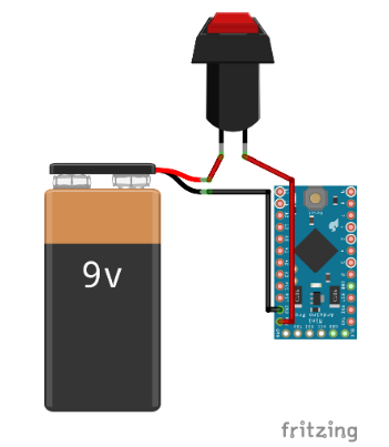
Note: The 9 volt battery clip wires and switch/pushbutton need to be soldered as in the fritzing diagram below:
When you've soldered up the Breadboard PCB you can continue onto the enclosure.
Enclosure
For the enclosure, you will need the M3 nuts and bolts listed above as well as your 3d printed enclosure and soldered up breadboard PCB.
-
Start by removing supports from the 3d printed case
-
Then mount the LCD display inside front of the case
-
Tighten the bolts and nuts.
- Mount the DHT22 sensor on the side of the case with an M3 bolt and nut.
- Mount the switch/pushbutton on the opposite side to the DHT22 sensor
- Add the PCB, Battery, ETC, to the inside of the case. (NOTE: I put a piece of paper on top of the battery to stop shorts amongst the pins on the PCB)
- Put the lid/bottom on the top of the case so it looks like this (NOTE: My Base_4_case.stl part didn’t stay in place well so I added a few pieces of Blu-Tack the edges of the part to hold it in place better. Whether you need this will depend on the tolerances of your 3d printer.)
