I wanted a GPS speedometer that is portable, robust, and looks okay. I had been messing around with 3D printing and exploring GPS modules for a few years and wanted to bring those skills together to design a device that could be readily made by others without too much need for specialist know-how. I wanted it to be as close to kit form as possible. I also wanted to find ways of reducing the development time of a device from inception to finished product – there has to be methods of eliminating design mistakes and reducing the number of print iterations. I was only partially successful at that – I followed many tangents to dead ends and printed hundreds of objects.
I’m happy that the final design achieved my goals:
- Portable – it fits in the hand, can be placed on a flat surface or held in a clamp, and can be powered from any USB outlet
- Robust – it can be handled roughly and won’t fall apart; the cable connection is both physically and electrically secure
- Appearance – a 3D-printed object never looks as good as an injection moulded commercial product, but I reckon this looks pretty good
While a GPS module provides more data than just speed, this device was always intended to be a single-purpose tool and not a multi-tool. The aim was to do just one thing and do it well – be a speedometer.
A deliberate design policy was to have no user controls.
When I started this project I shared my work and progress with the Core Electronics community in the forum. People gave me terrific support and suggestions.
To begin with, I made a box with openings on its sides for the boards. I soldered the wires between the boards while the boards were positioned on the box. The tight spaces made soldering quite difficult. In putting the boards into their places the wires pushed back like springs. While I got it to work I couldn’t recommend this method.
Somewhere along the way, the idea emerged of containing the wires inside a 3D-printed object. Initially, I left the wires insulated and soldered them into the through holes. It worked – the wires were no longer difficult to install. I called this unexpected construction method monobloc.
Soldering wires to the through holes is fine for a permanent assembly but I was developing the design and had to do much desoldering of boards and resoldering. There’s a limit to how many times this can be done without damaging the boards. It’s also good practice to minimise the handling and soldering of the GPS module.
I looked at how a board with soldered pins works so well when inserted into a header block. Taking a female header block apart I saw that the pin gets forced into a tiny metal fork. It’s such a tight fit that it is both physically and electrically stable. So I thought squeezing both the pin and wire into the same hole might work. It did. I found it is easier if the wires are uninsulated. This horrified some of my forum friends – the idea of a bundle of bare wires inside the bloc made them uneasy. What has to be understood is that each wire is inside its own PLA conduit so they cannot connect with other wires.
Using the insertion method rather than soldering means the boards can be easily unplugged and re-inserted without anything being damaged.
This method allows for easy installation of the wiring between boards without soldering and delivers a compact assembly. I’ve used the new technology of 3D printing to do something that can’t be done with old technology.
Even if you don’t want to make this device you might like to print the monobloc and examine how it works and apply the method to other builds.

An early design.
The device uses three electronic modules – a u-blox Neo 6M GPS receiver on a breakout board, an Arduino Nano microprocessor, and a TM1637 7-segment 4-digit LED display. It also has a piezo buzzer. Power is provided by a USB cable to the Nano. There are no switches – the device is turned on by connecting the USB cable to a power source.
The GPS receiver outputs a group of NMEA sentences to the Nano via software serial every second. The Nano sketch extracts just two parameters – speed in kph and UTC time – and displays the speed on the LED display.
The GPS receiver takes a short while after powering up to get a complete positional fix at which point the speed will be available. Before getting a fix, it will receive enough satellite data to have the UTC time. If the time is available but not the speed, the sketch displays the local time. If the speed is available and below 5 kph, the display alternates between the local time and speed.
The displayed speed is accurate although there is a slight lag between the actual current speed and the displayed value. This is generally not a practical problem, but I would like to understand why it occurs.
The sketch sends each sentence to the Nano’s hardware serial port. If the device is being powered from a PC or smartphone, then the data stream can be read and processed by programs such as the Arduino IDE monitor, u-blox’s u-center, or serial terminal programs. I built a custom app for an Android device that visualises the GPS data such as satellite signal strengths and map location. I’ve made that app available.
I do not use a GPS library but simply read each sentence arriving at the software serial port, identify it from the first six bytes, and extract the UTC time from the GPRMC sentence and the speed from the GPVTG sentence. I haven’t found it necessary to do a checksum on the sentences and I assume that if there is a null value in the speed field then a complete fix has not been achieved.
3D printing
Mid-level skill is needed.
Tinkercad
You need a Tinkercad account (free). You do not need to do any design in Tinkercad but you do need to be able to view files. It’s very helpful to rotate the objects and view them from all angles, especially the monobloc. The transparent feature allows the internal details, such as the conduits, to be viewed.
You need to know how to select an object and export it as an STL file for slicing.
Slicing
You need to know how to set the slicing parameters. The most important are:
- Layer thickness
- Wall count
- Infill
- Speed
- Support
- Bed adhesion
You need to understand how to orient an object for printing. I have presented objects at different orientations.
Do test pieces. Modify the parameters to get quick prints. Try scaling to get smaller test pieces. But, actually, I’ve done the hard work – just print them and use them.
Arduino
Mid level.
You need to know how to upload a sketch to the Nano. You don’t need to do any programming to use the sketch I’ve provided.
Electronics
Not required. But take care of the GPS and antenna – handle them as little as possible
Soldering
Not required unless you need to solder header pins to your boards. A soldering iron is used in softening the rails of the GPS & antenna holder.

Components
| Item | Description | Product Listing | |||
| GPS receiver | U-blox NEO-6M GPS module; header pins soldered in; other modules unlikely to be suitable without modifying the monobloc design | Core Electronics | |||
| Microprocessor | Arduino Nano; header pins soldered in | Core Electronics | |||
| Display | TM1637 4-digit 7-segment LED; 0.56 inch high; your choice of colour of the LEDs; MUST have through pins at both ends; can be central semicolon model or 4 decimal points; 0.36 inch high will be suitable if board dimensions are same; header pins soldered | ||||
| Buzzer | Piezo; passive | Ebay | |||
| Cable | Single core copper hookup wire (insulation to be stripped); core MUST be 0.5 mm; MUST NOT be multicore | Jaycar | |||
| 3D Printer Filament | PLA, any colours (black or other dark colours are difficult to work with as details are difficult to see – a light colour filament is almost necessary for the monobloc; I like grey) | Core Electronics | |||
| Screws (6x) | No.4 x 6 mm steel self-tapping | Jaycar | |||
Tools
- Sharp craft knife (for cleaning 3D printed parts and other uses)
- Sanding block (for removing small amounts of material from 3D printed parts that need to fit together)
- Magnetised screwdriver (to install screws inside the housing)
- Soldering iron (not for soldering but to soften the guide rails on the antenna holder and set the ends of sires into the monobloc)
Screws
Screws are your friend. Don’t be a purist and think you must design 3D-printed parts to fit together without help. Well-placed screws make things secure and easy to take apart. A magnetised screwdriver is almost a necessity. To magnetise a screwdriver just attach it to a magnet for 2 hours. It doesn’t have to be a particularly big magnet.


There are seven 3D-printed objects to make. I used Tinkercad for 3D designing and Cura for slicing. All objects were made on Ultimaker 2+ or Ultimaker 2+ Connect printers with PLA filament.
| Part | Print Time (H:MM) | Layer Height (mm) | Speed (mm/s) | Wall Count | Infil (%) | Support | |
| Antenna Retainer | 0:10 | 0.15 | 80 | 4 | 20 | off | |
| Monobloc | 1:20 | 0.15 | 80 | 2 | 20 | off | |
| Case | 2:49 | 0.15 | 80 | 4 | 20 | off | |
| Cable Retainer | 0:17 | 0.15 | 80 | 4 | 100 | off | |
| Bezel | 0:59 | 0.15 | 80 | 4 | 20 | off | |
| Button & Retainer | 0:04 | 0.2 | 100 | 4 | 20 | off | |
The circuit design is simple and can be tested on an assembly of breadboard and jumper wires. Writing a workable sketch was not hard. A breadboard/jumpers assembly is not robust and so unsuitable for a portable device. The main workload by far was in designing 3-D printed objects to securely hold all the components and provide a respectable housing.
I started with a hollow box that would hold the boards on its sides with wires connecting the boards. I managed to build a working device but installing the wires was so difficult I couldn’t recommend it. The confined space makes soldering difficult and you end up with a jumble of wires that push back like springs when you try to put the boards in place. I couldn’t recommend this method.
Somewhere along the way, the idea emerged of constraining the wires in a 3D-printed structure. After some experimenting, the idea developed into a solid block of plastic with small tunnels, or conduits, to hold the wires. The conduits are positioned so that when a wire is inserted it will run precisely between the appropriate pins on the boards. It took much effort to learn how to design and position the conduits, but the payoff is a fast and foolproof installation of the wiring and a compact assembly. To print and use this “monobloc” you do not need to be concerned with how I designed the conduits.
I didn’t expect the conduits to work as I didn’t think they would print successfully. But they do. They’re only 1.5mm in diameter and have to be positioned at all angles. They do not need support to be turned on in Cura – I think the infill provides adequate support to them. If you do turn on support, Cura will put support inside the conduits which would make them unusable. The outside of the conduits may have some drooping but that doesn’t matter. As far as I can tell the insides are always smooth. I’ve yet to be unable to get a wire completely through a conduit.
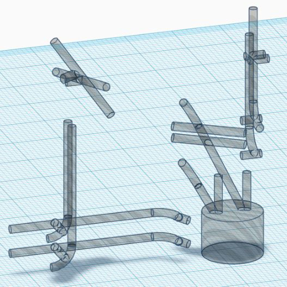
Here’s a Tinkercad image of the conduits without showing the bloc (the orientation is as it would be printed). The large cylindrical hole at the bottom right forms the recess for the piezo buzzer:
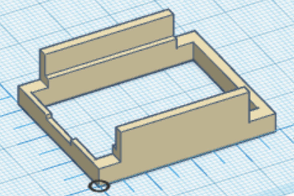
The antenna retainer should be the first object printed. The antenna on this model of GPS receiver is vulnerable to both physical and electrical damage. The cable and its connections are weak and easily broken if the antenna is left unsecured. The retainer holds the antenna securely against the module with the cable safely stowed. Once the antenna is secured within the retainer it should be kept this way permanently. Note that the tiny uFL connector is not designed to be frequently attached/detached. It is rated for only 30 attachment/detachment cycles.
The GPS/antenna assembly should be handled as little as possible as it is vulnerable to electrostatic damage. An anti-static mat and wrist grounding should be used when handling.

The monobloc is the heart of the assembly. I find that a line thickness of 0.15mm and a speed of 80 or even 100 mm/s gives good results.
Conduit openings:
The conduit openings might be closed over to some extent, especially on the top and bottom surfaces. Use the sharp point of a craft knife to ream them out and open them up.
One though-hole for the Nano board is deliberately blocked off at one end. DO NOT OPEN THIS UP WITH A BLADE. The blocking prevents the Nano 5V pin from contacting the antenna receptacle on the GPS board.
The wire must be uninsulated single-core copper of 0.5 mm diameter. I take the insulated hookup wire and strip off the insulation. For most conduits, I use 8 cm lengths of wire, and some require 10 cm.
Typically a wire is inserted into a conduit opening and pushed through using thin-nosed pliers. The pliers grip the wire just a few mm from the opening so the wire moves in just a few mm at a time. Trying to push in more than that will lead to the wire kinking. A wire with a kink or nick should be discarded. If resistance is felt, push, pull, and twist the wire. I have found it always gets past the resistance.
The top image is transparent, revealing the conduits; the right image is the correct orientation for 3D printing.

Threading the Monobloc
I call inserting a wire into and all the way through a conduit “threading”.
There are ten conduits to be threaded:
- Nano 5V to TM1637 5V
- Nano GND to TM1637 GND
- TM1637 CLK to Nano D10
- TM1637 DIO to Nano D12
- TM1637 5V to GPS VCC
- TM1637 GND to GPS GND
- GPS RX to Nano D4
- GPS TX to Nano D3
- Buzzer + to Nano D10
- Buzzer GND to Nano GND
If you use insulated wire when stripping the wire it is important to avoid nicking the wire as threading the conduits can require pulling strongly on the wire and it can break at a nick. With some conduits, the wire is inserted into one opening and pushed through until it emerges from the other opening. Some conduits include a significant change of direction and require a different approach.
Once threaded, I trim the ends and secure them by setting them into the PLA of the bloc with the heat of a soldering iron.
Most of the conduits are not simple single runs directly from one hole to another. Threading requires varying approaches. Here are some pics and notes on how I threaded them. There can be more than one way to thread a complicated conduit.
The following images show just the conduits of interest, rather than all of them. You should be viewing the Tinkercad file while threading a conduit. Rotate the image to view the conduit from all angles. This will aid you when you are threading the conduits.

#7 GPS RX to Nano D4 and 8. GPS TX to Nano D3
These are the simplest as they are direct single runs

#1 Nano 5V to TM1637 5V
#2 Nano GND to TM1637 GND
#5 TM1637 5V to GPS VCC
#6 TM1637 GND to GPS GND


Mounting the components
This is where all the hard careful work pays off. Once you’ve threaded all the conduits in the monobloc, you just push each component into its place. You must get the orientations correct:
- Buzzer: with the recess for the buzzer facing you and to your right (as in the pic immediately above), insert the pins of the buzzer into the pin holes inside the recess with the + pin to the left
- Nano: there are two possible ways to insert the Nano, only one of which is correct; the USB connector must be at the same end as the buzzer (the monobloc’s rear)
- Display: also two possible ways to insert, only one of which will work. With the Nano to the bottom, insert the display with the lettering facing the right way up
- GPS: there is only one possible way to insert the GPS module
All electrical connections should be sound as the holes enforce close and tight contact between the component pins and the wires. Testing can be done by loading the Nano with the sketch and viewing the GPS output in the Arduino IDE monitor. The buzzer, display, and GPS should all be heard/seen to be working.
Components can be easily detached from the monobloc as they are not soldered in.
It’s essential for you to be a Tinkercad user. You don’t need to do any design or modifications of the objects but you need to view and examine the objects in detail, especially the general arrangements and the monobloc.
You need to closely examine the monobloc – you need to understand the conduits (use the Transparent command).
You need to be able to select the object (ensuring it is correctly orientated and sitting on the workplane) and export the STL file.
I’ve put all my Tinkercad designs for this project into a collection called ProjectK and started the names of all designs with “Redchat’s ProjectK-”. I’ve made all of those designs public so if you have a Tinkercad account you’ll be able to view them, make a copy (and edit if you need to), and export STL files for printing.
In Tinkercad, do a search on “Redchat’s” and you’ll see all of the designs on one page, or use this link: Redchat's Tinkercad project files
Some designs are for illustration and are not for printing. Rather than providing the STL files I’m asking you to export them from the Tinkercad designs. Be sure to select only the shape to be printed and not all shapes on the screen and that the object is oriented the way I suggest and it is sitting on the workplane.
Once you’ve printed the antenna holder and the monobloc, you can insert the electronic components, power it up and run the device. All the other printed parts are to do with housing the device.


#define startTitle "GPS Speedometer, Aug 2023" #include#include #define DEBUG //comment out to suppress DEBUG statements #define simRequested 0 //1 for sim mode, 0 for live mode #define buzzerEnabled 1 //1 to enable buzzer, 0 to suppress #define pinBZR 6 //real pin is 6 #define pinLED 13 #define pinCLK 12 #define pinDIO 10 #define pinSoftSerial_RX 3 #define pinSoftSerial_TX 4 #define brightnessNormal 4 #define brightnessMin 0 #define brightnessMax 7 #define GPStimeout 1000 #define durationGPSintroOutput 2000 TM1637Display display(pinCLK, pinDIO); SoftwareSerial mySerial(pinSoftSerial_RX, pinSoftSerial_TX); // RX, TX boolean haveTime, haveSpeed, overflowOccurred; int speedForDisplay, hourLocalasInt, minuteLocalasInt, timeLocalasInt, timeDisplayed; float speed; String RMCsentence, VTGsentence, speedAsString, timeUTCField, speedField; const uint8_t dataAllDots[] = {0x80, 0x80, 0x80, 0x80}, dataDot0[] = {0x80, 0x00, 0x00, 0x00}, dataDot1[] = {0x00, 0x80, 0x00, 0x00}, dataDot2[] = {0x00, 0x00, 0x80, 0x00}, dataDot3[] = {0x00, 0x00, 0x00, 0x80}; const int RunningDotDelay = 20, serialTimeoutDuration = 1000, //milliseconds softSerialTimeoutDuration = 1000, GPStimeoutDuration = 20, serialBaudRate = 9600, softSerialBaudRate = 9600; //****************************SETUP************************************* void setup() { unsigned long startMark, duration; //initialise serial port Serial.begin(serialBaudRate); Serial.setTimeout(serialTimeoutDuration); pinMode(pinBZR, OUTPUT); pinMode(pinLED, OUTPUT); display.setBrightness(brightnessNormal); //make intro message & test hardware Serial.println(startTitle); //to monitor display.showNumberDec(8888); delay(500); display.clear(); //pulse on board LED for (int i = 0; i < 5; i++) { digitalWrite(pinLED, HIGH); delay(50); digitalWrite(pinLED, LOW); delay(50); } //sound buzzer // tone(pinBZR, 2000, 100); Serial.println(); Serial.print("simRequested:"); Serial.println(simRequested); //send GPS output to monitor for a brief duration Serial.println("***TEST GPS OUTPUT***"); mySerial.begin(softSerialBaudRate); mySerial.setTimeout(softSerialTimeoutDuration); startMark = millis(); while ((millis() - startMark) < 2000) { if (mySerial.available()) Serial.write(mySerial.read()); } Serial.println("***TEST DONE***"); Serial.println(); //empty soft serial buffer while (mySerial.available()) Serial.write(mySerial.read()); } //*****************************LOOP******************************** void loop() { while (!mySerial.available());//wait till a byte is avail. Serial.println(); doBusyTasks(); //get GPS output if (simRequested) doSim(); //simulate speed else doIdleTasks(); //process GPS output } //****************************** void doBusyTasks() { //busy period is when GPS is outputting sentences; //read & store all available sentences with as little other //activity as possible; //return when idle for more than GPStimeoutDuration (ms), meaning busy period is over; unsigned long markTimeStart, markTimeEnd, markTimeLastCharRead = 0, markX = 0, markY = 0, elapsedTimeSinceLastCharRead = 0; boolean timeout = false; String sentence; digitalWrite(pinLED, LOW); markTimeStart = micros(); markTimeLastCharRead = markTimeStart; //store time count at start of procedure while (mySerial.available() == 0) {}; //do nothing till first byte arrives //read first two sentences -- RMC & VTG RMCsentence = (mySerial.readStringUntil('\n')) + '\n'; //restore Serial.print(RMCsentence); VTGsentence = (mySerial.readStringUntil('\n')) + '\n'; //restore Serial.print(VTGsentence); //read remaining sentences while (!timeout) { while (mySerial.available() > 0) { //any data from GPS? sentence = (mySerial.readStringUntil('\n')) + '\n'; //restore Serial.print(sentence); markTimeLastCharRead = micros(); //reset time mark } //no data avail., timeout? elapsedTimeSinceLastCharRead = (micros() - markTimeLastCharRead); if (elapsedTimeSinceLastCharRead > GPStimeoutDuration) timeout = true; } if (mySerial.overflow()) { digitalWrite(pinLED, HIGH); // Serial.println(); // Serial.println("Buffer overflowed!"); } } void doIdleTasks() /****************/ { //during period when GPS is NOT outputting sentences; //process stored sentences & take action unsigned long markTimeStart, markTimeEnd; markTimeStart = micros(); // IdentifyAndAssignStoredSentences(); ExtractDataAndProcess(); markTimeEnd = micros(); // Serial.println((markTimeEnd - markTimeStart) / 1000); //ms } void doSim() { Serial.print("SIM mode"); SimulateSpeed(); //simulate till board reset } //****************************** void ExtractDataAndProcess() { Get_timeUTC(); if (haveTime) { GetSpeed(); ManageDisplayContent(); } } //****************************** void GetSpeed() { //the valid flag field is the 8th in the VTG sentence; //need to determine positions of 7th & 8th commas int posAlpha, posBeta = -1; String speedWithoutDecimalPoint; for (int i = 1; i <= 8; i++) { posAlpha = posBeta; posBeta = VTGsentence.indexOf(',', posAlpha + 1); } //get speed as a string, will be in kph with three decimal places speedField = VTGsentence.substring(posAlpha + 1, posBeta); Serial.print("speed:"); Serial.println(speedField); if (speedField != "") { haveSpeed = true; speedAsString = speedField; //convert from string to numeric speed = speedField.toFloat(); //produces a float number to no more //than 2 decimal places int index = speedAsString.indexOf('.'); //find the period speedAsString.remove(index); //remove from 2nd dec place to end speedForDisplay = speedAsString.toInt(); //convert to integer // Serial.print(speedForDisplay); // Serial.println("kph"); } } //****************************** void Get_timeUTC() { //the UTC time field is the 2nd in the RMC sentence; //need to determine positions of 1st & 2nd commas int posAlpha, posBeta = -1; String hourLocalAsStr, minuteLocalAsStr; for (int i = 1; i <= 2; i++) { posAlpha = posBeta; posBeta = RMCsentence.indexOf(',', posAlpha + 1); } timeUTCField = RMCsentence.substring(posAlpha + 1, posBeta); if (timeUTCField != "") { Serial.print("UTC:"); Serial.println(timeUTCField); haveTime = true; //determine local time hourLocalAsStr = timeUTCField; hourLocalAsStr = hourLocalAsStr.substring(0, 2); minuteLocalAsStr = timeUTCField; minuteLocalAsStr = minuteLocalAsStr.substring(2, 4); hourLocalasInt = hourLocalAsStr.toInt() + 10; minuteLocalasInt = minuteLocalAsStr.toInt(); if (hourLocalasInt > 12) hourLocalasInt = hourLocalasInt - 12; timeLocalasInt = (hourLocalasInt * 100) + minuteLocalasInt; // Serial.print("local:"); // Serial.println(timeLocalasInt); } else { haveTime = false; DisplayRunningDot(); } } //****************************** void DisplayEights() { uint8_t data[] = { 0xff, 0xff, 0xff, 0xff }; display.setSegments(data); delay(200); display.clear(); } //****************************** void SimulateSpeed() { int interval = 500; //generate a speed value, changing it every set time interval //from 35 to 44 Serial.print("SIM"); for (speedForDisplay = 35; speedForDisplay <= 44; speedForDisplay++) { speedForDisplay = speedForDisplay; DisplaySpeed(); speed = speedForDisplay; delay(interval); } //from 44 to 35 for (speedForDisplay = 44; speedForDisplay >= 35; speedForDisplay--) { DisplaySpeed(); speed = speedForDisplay; delay(interval); } //from 35 to 85 for (speedForDisplay = 35; speedForDisplay <= 85; speedForDisplay++) { DisplaySpeed(); speed = speedForDisplay; delay(interval); } } void DisplaySpeed() { //display the speed on the TM1637 display // display.showNumberDecEx(speedForDisplay, 0b00100000, false, 4, 0); // display.showNumberDecEx(speedForDisplay, 0b00000000, false, 4, 0); display.showNumberDec(speedForDisplay); } void DisplayTime() { //displaying takes a significant time, //so only do it if time has changed if (timeLocalasInt != timeDisplayed) { display.showNumberDecEx(timeLocalasInt, 0b01000000, false, 4, 0); timeDisplayed = timeLocalasInt; } } void DisplayRunningDot() { display.clear(); display.setSegments(dataDot0); display.setSegments(dataDot1); display.setSegments(dataDot2); display.setSegments(dataDot3); display.setSegments(dataDot2); display.setSegments(dataDot1); display.setSegments(dataDot0); } void ManageDisplayContent() { //display speed, running dot or time if (haveSpeed && speed > 4) DisplaySpeed(); else if (haveSpeed && speed <= 4) { DisplayTime(); delay(1000); display.clear(); DisplaySpeed(); delay(1000); // DisplayTime(); } else if (haveTime) DisplayTime(); else DisplayRunningDot(); }
Ideas for Improvement
- Automatically adjust display brightness based on time of day – needs to be dimmed at night
- Automatically adjust the computation of local time for daylight saving
- Correct the algorithm that derives local time – 10:00 am is displayed as 22:00
- Develop a way of selecting sim mode without needing to recompile and reinstall the sketch
- Put the display to sleep if the speed is zero for a specified length of time
- Find out what causes the lag between actual speed and displayed value
I put a lot of effort into developing techniques to reduce the number of print iterations. These arise either because the device is a new design and trial and error cannot be avoided, or because of design mistakes that don’t become apparent until components are printed and tested.
The device comprises four electronic components and seven 3D-printed components. All of the 3D-printed components have to be well-designed and free of mistakes for the entire assembly to work.
By far the most valuable technique to reduce print iterations was to make virtual models of all the electronic components – GPS module, antenna, Nano, display, and buzzer. I made these to an accuracy of 1 mm. The models need to be detailed to the extent that all sub-components on a board that could make contact with other components are included. This isn’t as difficult or time-consuming as it might at first seem. The models can be reused in other projects and you might find suitable models already in the public domain (I’ve made my models public).
After creating accurate virtual models of components, do an on-screen “assembly” of your 3D creations with the components – if they don’t “fit” on-screen then the real objects won’t fit.
To test a particular functionality, print just a section of the object rather than the entire object.
Reduce print times of test pieces by reducing infill and wall count. Reducing the scale of a test piece to say, one-half, can be helpful.
I built an Android app using MIT App Inventor that can receive the NMEA sentences via an OTG cable and visualise the GPS data. This is handy for monitoring the GPS during startup. The satellite signals are shown as bar graphs. All the GPS-derived parameters are shown, such as satellite signal strengths, latitude, longitude, altitude, and course. A map can be selected that will show your current location.
The app is public and can be downloaded here:

All 3D printing was done at the maker spaces of the Melbourne City Council libraries – where the equipment is fabulous and the staff stupendous.
Melbourne library maker spaces
Thanks also to Core Electronics forum contributors for being a great sounding board in my early efforts.
