

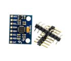
LSM6DSO 3D Accelerometer and Gyro Carrier with Voltage Regulator
Available with a lead time
Expect dispatch between Jul 27 and Jul 28
Quantity Discounts:
- 10+ $28.75 (exc GST)
- 25+ $27.85 (exc GST)
 |
This board is a compact (0.5" × 0.9") breakout board for ST’s LSM6DSO inertial module, which features a 3-axis digital linear accelerometer and 3-axis digital rate gyroscope; Pololu therefore recommend careful reading of the LSM6DSO datasheet (3MB pdf) before using this product. The LSM6DSO is a great IC, but its small package makes it difficult for the typical student or hobbyist to use. It also operates at voltages below 3.6 V, which can make interfacing difficult for microcontrollers operating at 5 V. This carrier board addresses these issues by incorporating additional electronics, including a 3.3 V voltage regulator and level-shifting circuits, while keeping the overall size as compact as possible. The board ships fully populated with its SMD components, including the LSM6DSO, as shown in the product picture.
The LSM6DSO inertial measurement unit (IMU) has many configurable options, including dynamically selectable sensitivities for the accelerometer and gyro, a choice of output data rates, and two independently-programmable external inertial interrupt pins. The accelerometer and gyro can be individually turned on and off to save power. The sensor can be configured and its readings can be accessed through a digital interface, which can be configured to operate in either I²C (TWI) or SPI mode. The MIPI I3C protocol is also supported on the I²C pins.
The six independent acceleration and angular rate readings (sometimes called 6DOF) provide data that a microcontroller or computer can use to calculate the orientation of the LSM6DSO on two axes (roll and pitch; a magnetometer is generally required to compute yaw accurately). With an appropriate algorithm, the gyro can be used to very accurately track rotation on a short timescale, while the accelerometer can help compensate for gyro drift over time by providing an absolute frame of reference.
The carrier board includes a low-dropout linear voltage regulator that provides the 3.3 V required by the LSM6DSO, which allows the sensor to be powered from a 1.8 V to to 5.5 V. The regulator output is available on the VDD pin and can supply almost 150 mA to external devices. The breakout board also includes a circuit that shifts the I²C clock and data lines to the same logic voltage level as the supplied VIN, making it simple to interface the board with 5 V systems. The pins are spaced to work with standard 0.1" (2.54 mm) male headers and 0.1" female headers (available separately), making the board easy to use with solderless breadboards and 0.1" perfboards. The board has two mounting holes that work with #2 and M2 screws (not included).
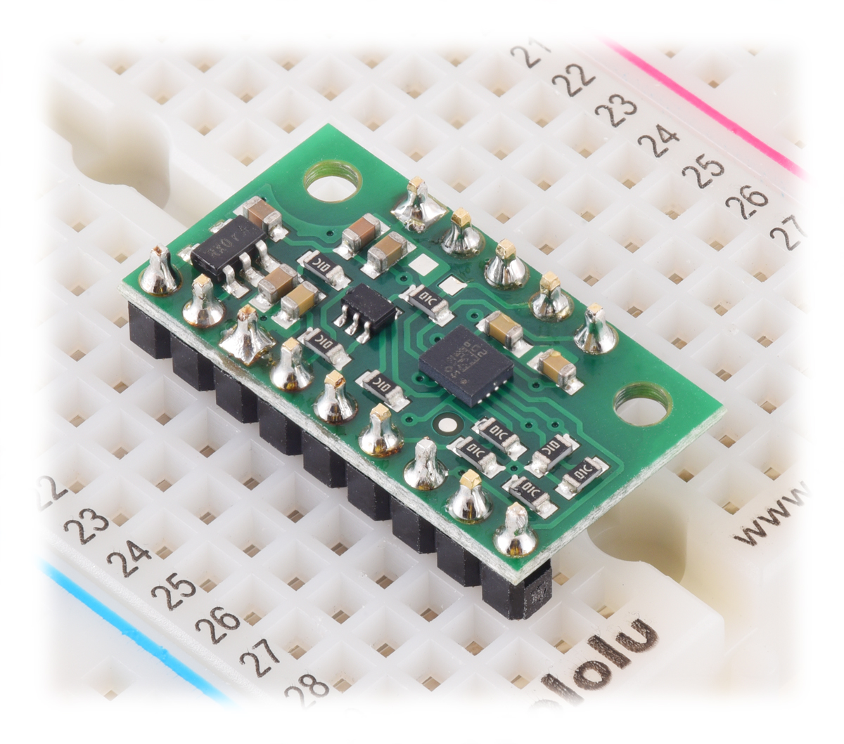 |
LSM6DSO 3D Accelerometer and Gyro Carrier with Voltage Regulator in a breadboard. |
|---|
Compared to the LSM6DS33, the LSM6DSO offers various improvements like lower noise and a higher maximum output data rate for the gyro. In addition to standard operation as an I²C or SPI slave (Mode 1), the LSM6DSO also supports additional specialized modes with a secondary interface: it can act as a master (sensor hub) on a second I²C bus (Mode 2), or it can provide an auxiliary SPI slave interface that is useful for electronic and optical image stabilization (EIS/OIS) applications (Mode 3/4). See the datasheet and application note (2MB pdf) for more information about these modes. Pololu's carrier board brings out these secondary interface pins on the side opposite the main connections.
This LSM6DSO carrier is pin-compatible with Pololu's earlier LSM6DS33 carrier (and many of Pololu's other ST I²C/SPI sensor carriers), and the orientation of the sensor axes is the same. The ICs also use the same I²C address and have similar register interfaces, so code written to interface with the LSM6DS33 can probably be modified to work with an LSM6DSO without too much trouble.
Specifications
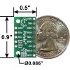
- Dimensions: 0.5" × 0.9" × 0.1" (13 × 23 × 3 mm)
- Weight without header pins: 0.6 g (0.02 oz)
- Operating voltage: 1.8 V to 5.5 V
- Supply current: 1 mA
- Output format (I²C/SPI):
- Accelerometer: one 16-bit reading per axis
- Gyro: one 16-bit reading per axis
- Sensitivity range (configurable):
- Accelerometer: ±2, ±4, ±8, or ±16 g
- Gyro: ±125, ±245, ±500, ±1000, or ±2000°/s
Using the LSM6DSO
Connections
Regardless of the interface being used to communicate with the LSM6DSO, its VIN pin should be connected to a 1.8 V to 5.5 V source, and GND should be connected to 0 volts. (Alternatively, if you are using the board with a logic voltage of 3.3 V or lower, you can leave VIN disconnected and bypass the built-in regulator by connecting the logic supply directly to VDD.)
A minimum of two logic connections is necessary to use the LSM6DSO in I²C mode (this is the default mode): SCL and SDA. These pins are connected to built-in level-shifters that make them safe to use at voltages over 3.3 V; they should be connected to an I²C bus operating at the same logic level as VIN. The remaining pins are not connected to level-shifters on the board and are not 5V-tolerant, but Pololu's 4-channel bidirectional logic level shifter can be used externally with those pins to achieve the same effect.
To use the LSM6DSO in SPI mode, four logic connections are typically used: SPC, SDI, SDO, and CS. These should be connected to an SPI bus operating at the same logic level as VIN. The SPI interface operates in 4-wire mode by default, with SDI and SDO on separate pins, but it can be configured to use 3-wire mode so that SDO shares a pin with SDI.
 |
LSM6DSO 3D Accelerometer and Gyro Carrier with Voltage Regulator, labeled top view. |
|---|
Pinout
| PIN | Description |
|---|---|
| VDD | Regulated 3.3 V output. Almost 150 mA is available to power external components. (If you want to bypass the internal regulator, you can instead use this pin as a 1.8 V to 3.3 V input with VIN disconnected.) |
| VIN | This is the main 1.8 V to 5.5 V power supply connection. The SCL/SPC and SDA/SDI level shifters pull the I²C and SPI bus high bits up to this level. |
| GND | The ground (0 V) connection for your power supply. Your I²C or SPI control source (and any devices connected to the secondary interface) must also share a common ground with this board. |
| SDA/SDI/SDO | Level-shifted I²C/I3C data line and SPI data in line (also doubles as SDO in 3-wire mode): HIGH is VIN, LOW is 0 V |
| SCL/SPC | Level-shifted I²C/I3C/SPI clock line: HIGH is VIN, LOW is 0 V |
| SDO/SA0 | SPI data out line in 4-wire mode: HIGH is VDD, LOW is 0 V. Also used as an input to determine I²C slave address (see below). This I/O is not level-shifted. |
| CS | SPI enable (chip select). Pulled up to VDD to enable I²C communication by default; drive low to begin SPI communication. This input is not level-shifted. |
| INT2/DEN | Programmable interrupt, a 3.3-V-logic-level output. Can also be used as a data enable trigger input or, in Mode 2, a sensor hub data ready input (MDRDY). This I/O is not level-shifted. |
| INT1 | Programmable interrupt, a 3.3-V-logic-level output. This output is not level-shifted. |
| SDx | Mode 2: I²C master data line (MSDA) Mode 3/4: Auxiliary SPI data in line (SDI) (also doubles as auxiliary SDO in 3-wire mode) This I/O is not level-shifted. |
| SCx | Mode 2: I²C master clock line (MSCL) Mode 3/4: Auxiliary SPI clock line (SCK) This I/O is not level-shifted. |
| SDO_Aux | Mode 3/4: Auxiliary SPI data out line in 4-wire mode This output is not level-shifted. |
| OCS_Aux | Mode 3/4: Auxiliary SPI enable (chip select); pulled up by default. This input is not level-shifted. |
Schematic diagram
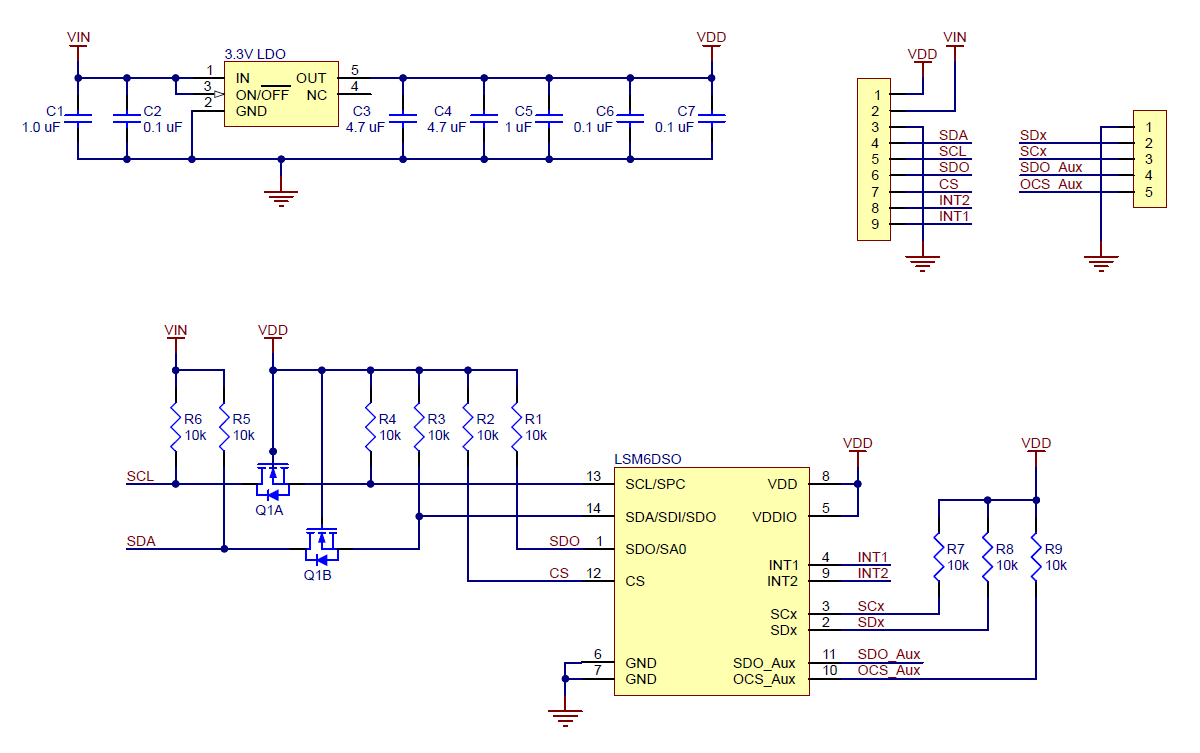 |
The above schematic shows the additional components the carrier board incorporates to make the LSM6DSO easier to use, including the voltage regulator that allows the board to be powered from a single 1.8 V to 5.5 V supply and the level-shifter circuit that allows for I²C and SPI communication at the same logic voltage level as VIN. This schematic is also available as a downloadable PDF (100k pdf).
I²C communication
With the CS pin in its default state (pulled up to VDD), the LSM6DSO can be configured and its readings can be queried through the I²C bus. Level shifters on the I²C clock (SCL) and data lines (SDA) enable I²C communication with microcontrollers operating at the same voltage as VIN (1.8-5.5V). A detailed explanation of the protocol can be found in the LSM6DSO datasheet (3MB pdf), and more detailed information about I²C in general can be found in NXP’s I²C-bus specification (1MB pdf).
In I²C mode, the sensor’s 7-bit slave (target) address has its least significant bit (LSb) determined by the voltage on the SA0 pin. The carrier board pulls SA0 to VDD through a 10 kO resistor, making the LSb 1 and setting the slave address to 1101011b by default. If the selected slave address happens to conflict with some other device on your I²C bus, or if you want to use two LSM6DSO sensors on the same bus, you can drive SA0 low to set the LSb to 0 (which sets the slave address to 1101010b).
The I²C interface on the LSM6DSO is compliant with the I²C fast mode (400 kHz) standard, and the sensor also supports MIPI I3C communication through the same pins.
SPI communication
To communicate with the LSM6DSO in SPI mode, the CS pin (which the board pulls to VDD through a 10 kO resistor) must be driven low before the start of an SPI command and allowed to return high after the end of the command. Level shifters on the SPI clock (SPC) and data in (SDI) lines enable SPI communication with microcontrollers operating at the same voltage as VIN (1.8 V to 5.5 V).
In the default 4-wire mode, the sensor transmits data to the SPI master on a dedicated data out (SDO) line that is not level-shifted. If the SPI interface is configured to use 3-wire mode instead, the SDI line doubles as SDO and is driven by the LSM6DSO when it transmits data to the master. A detailed explanation of the SPI interface on the LSM6DSO can be found in its datasheet (3MB pdf).
Sample Code
Pololu have written a basic Arduino library for the LSM6 that makes it easy to interface this sensor with an Arduino or Arduino-compatible board like an A-Star. The library makes it simple to configure the LSM6DSO and read the raw accelerometer and gyro data through I²C.
Protocol hints
The datasheet provides all the information you need to use this sensor, but picking out the important details can take some time. Here are some pointers for communicating with and configuring the LSM6DSO that Pololu hope will get you up and running a little bit faster:
- The accelerometer and gyro are in power-down mode by default. You have to turn them on by writing the appropriate values to the CTRL1_XL and CTRL2_G registers.
- The register address automatically increments during a multiple byte access, allowing you to read or write multiple registers in a single I²C or SPI command. Unlike with some other ST sensors, the auto-increment is enabled by default; you can turn it off with the IF_INC field in the CTRL3_C register.
- In addition to the datasheet, ST provides an application note (2MB pdf) containing additional information and hints about using the LSM6DSO.
Dimensions
| Size: | 0.5" × 0.9" × 0.1" |
|---|---|
| Weight: | 0.6 g |
General specifications
| Interface: | I²C/I3C, SPI1 |
|---|---|
| Minimum operating voltage: | 1.8 V |
| Maximum operating voltage: | 5.5 V |
| Measurement range: | ±2, ±4, ±8, or ±16 g (accelerometer) ±125, ±250, ±500, ±1000, or ±2000°/s (gyro)2 |
| Supply current: | 1 mA |
Identifying markings
| PCB dev codes: | imu06a |
|---|---|
| Other PCB markings: | 0J13680 |
Notes:
File downloads
-
LSM6DSO datasheet (3MB pdf)
-
AN5192: LSM6DSO application note (2MB pdf)
This application note from ST provides usage information and application hints for the LSM6DSO accelerometer and gyro.
-
UM10204 I²C-bus specification and user manual (1MB pdf)
The official specification for the I²C-bus, which is maintained by NXP.
-
Schematic diagram for the LSM6DSO 3D Accelerometer and Gyro Carrier with Voltage Regulator (100k pdf)
-
Dimension diagram of the LSM6DSO 3D Accelerometer and Gyro Carrier with Voltage Regulator (1MB pdf)
-
3D model of the LSM6DSO 3D Accelerometer and Gyro Carrier with Voltage Regulator (4MB step)
-
Drill guide for the LSM6DSO 3D Accelerometer and Gyro Carrier with Voltage Regulator (20k dxf)
This DXF drawing shows the locations of all of the board’s holes.
Recommended links
-
An Arduino library for interfacing with the LSM6DSO and LSM6DS33 accelerometer and gyro ICs.
Exact shipping can be calculated on the view cart page (no login required).
Products that weigh more than 0.5 KG may cost more than what's shown (for example, test equipment, machines, >500mL liquids, etc).
We deliver Australia-wide with these options (depends on the final destination - you can get a quote on the view cart page):
- $3+ for Stamped Mail (typically 10+ business days, not tracked, only available on selected small items)
- $7+ for Standard Post (typically 6+ business days, tracked)
- $11+ for Express Post (typically 2+ business days, tracked)
- Pickup - Free! Only available to customers who live in the Newcastle region (must order online and only pickup after we email to notify you the order is ready). Orders placed after 2PM may not be ready until the following business day.
Non-metro addresses in WA, NT, SA & TAS can take 2+ days in addition to the above information.
Some batteries (such as LiPo) can't be shipped by Air. During checkout, Express Post and International Methods will not be an option if you have that type of battery in your shopping cart.
International Orders - the following rates are for New Zealand and will vary for other countries:
- $12+ for Pack and Track (3+ days, tracked)
- $16+ for Express International (2-5 days, tracked)
If you order lots of gear, the postage amount will increase based on the weight of your order.
Our physical address (here's a PDF which includes other key business details):
40 Aruma Place
Cardiff
NSW, 2285
Australia
Take a look at our customer service page if you have other questions such as "do we do purchase orders" (yes!) or "are prices GST inclusive" (yes they are!). We're here to help - get in touch with us to talk shop.
Have a product question? We're here to help!
 22pF Ceramic Disc CapacitorSKU: CE05189 Brand: Core Electronics50V Voltage Rating, 5% Tolerance. Single pitch lead spacing.
-
- A3213 Hall Effect SensorSKU: 014-A3213EUA-TUnlike other Hall-effect switches, either a north or south pole of sufficient st ...
- MPU-6050 Module 3 Axis Gyroscope + AccelerometerSKU: 018-MPU-6050 Brand: Core ElectronicsA 3-axis gyroscope and 3-axis accelerometer housed on a development board ready ...
Videos
View AllGuides

Getting Started With Inertial Measurement Units | Exploring Degrees Of Freedom

The Maker Revolution

Getting Hands-on with Sensors
Projects

Hogwarts Legacy Broom Flight Controller

WhyzaGC - Feather ESP32 addon to the MightyOhm Gieger Counter

Makers love reviews as much as you do, please follow this link to review the products you have purchased.
Product Comments