Is it hot in here, or is it just my Raspberry Pi? A Raspberry Pi sitting on a desk doing nothing is kind of boring. However, a Raspberry Pi that can measure the temperature and make decisions based off that information is awesome!
The Raspberry Pi lacks analogue input, and while it’s possible to use an Analogue to Digital Converter (ADC), the DS18B20 is a fantastic, easy to use digital sensor that uses the Dallas 1 wire communication interface. Fortunately for us, the Raspberry Pi comes with built in software handling for 1 wire sensors which makes using sensors such as the DS18B20 pretty straightforward.
What is 1-Wire Communication
 The Dallas 1-Wire protocol is a method of serial communication designed for simple communication between 1 Master and multiple Slave devices. Serial communication means that data is sent bit-by-bit along a single data line.
1 wire communication is most commonly used for temperature sensors, EEPROM chips, and other simple devices. Unlike other serial communication protocols such as I2C, which allows for device IDs/addresses to be assigned and handled by the master device, 1 wire devices have an unchangeable, factory set device ID. By differentiating between unique device IDs, you can chain multiple slave devices on a single data bus.
Most 1 wire devices use 'parasitic power'. Parasitic power allows for the slave device to receive power on the same wire as the data, which means that only two contacts are required for 1 wire communication; Ground, and Data/Power. Typical supply power for 1 wire communication is between 2.85V - 5.25V, although 3.3V and 5V logic levels are normally used. The data line is held high when no data is being transmitted, and a small capacitor is used to store charge whenever the data line is pulled low as a bit is trasmitted. The DS18B20 sensor doesn't use parasitic power, so it has a seperate power line to the data line, resulting in 3 contacts for operation.
The TL;DR of 1-Wire communication:
- Single data line
- Serial communication
- Unique, factory-set device ID
- Parasitic power or seperate power line
- Multiple slave devices allowed on a single data line
- Only 1 master device per bus
- 2.85V - 5.25V power
So, without further ado, let’s get started!
Required Components
To complete this tutorial you will need:
- Raspberry Pi Board (we recommend the Pi 3)
- Waterproof DS18B20 Sensor
- 3 Pin Terminal Block
- RGB LED
- 3x 220 Ohm Resistors (the Sparkfun Resistor Pack is a great choice)
- 4.7K Resistor
- Male-Female Jumper Wires
- Male-Male Jumper Wires
Whilst it's not striclty required, do yourself a favour and get a Pimoroni Pibow Coupe case. Along with being sturdy, attractive, and providing full access to ports and GPIO pins, the clearly laid out GPIO pin labelling will change your life.
Raspberry Pi Board Setup
Before we can use our temperature sensor, we need to configure the Raspberry Pi to use the 1 wire interface. There are a couple of steps in this so make sure you don’t miss anything. We'll be using the latest version of Raspbian for this tutorial.
By default to save resources, the Raspberry Pi doesn't load up every available module, so we need to let it know that we want to load up the modules that we need to use 1 wire temperature sensors.
Open a Terminal window and type:
sudo modprobe w1-gpio
sudo modprobe w1_therm

This is a good start, but when we go to boot up our Pi next time, we will have to go through that step again which can be a pain. But we can tell our Pi to load these at startup everytime by going back to the Terminal and typing:
sudo nano /etc/modules
This will open the modules file. Scroll down to the bottom and add 'w1-gpio' and 'w1_therm' as seperate lines after everything else. To save the changes to this file press Ctrl + X, it will prompt you with yes (y) or no (n), hit y, and then Enter to complete the save. You should now be back at the main Terminal window.
The final step is to load up the config.txt file by typing:
sudo nano /boot/config.txt
Again, scroll down to the bottom and after everything else, add 'dtoverlay=w1-gpio' as a seperate line, then Ctrl + X, y, and Enter to save the changes.
Sweet beans, now our Raspberry Pi should have the 1 wire interface ready for use. It is important to note that GPIO pin 4 is the designated pin for 1 wire communication on the Raspberry Pi. It’s possible to change this pin, but it’s easier to keep it as is.
The Circuit
To test our temperature sensor we’re going to build a simple circuit that we can program to act as a simple thermometer.
Our goal is to read the temperature from our sensor and define 3 states using that data: too hot, too cold, and comfortable. We’ll use the Red LED pin to indicate when it is too hot, the Blue LED pin to indicate when it is too cold, and the Green LED pin to indicate when the temperature is in a range that is comfortable.
*Whenever you're connecting anything to the GPIO pins on the Raspberry Pi, make sure that your Pi is turned off and unplugged from power before hand.*
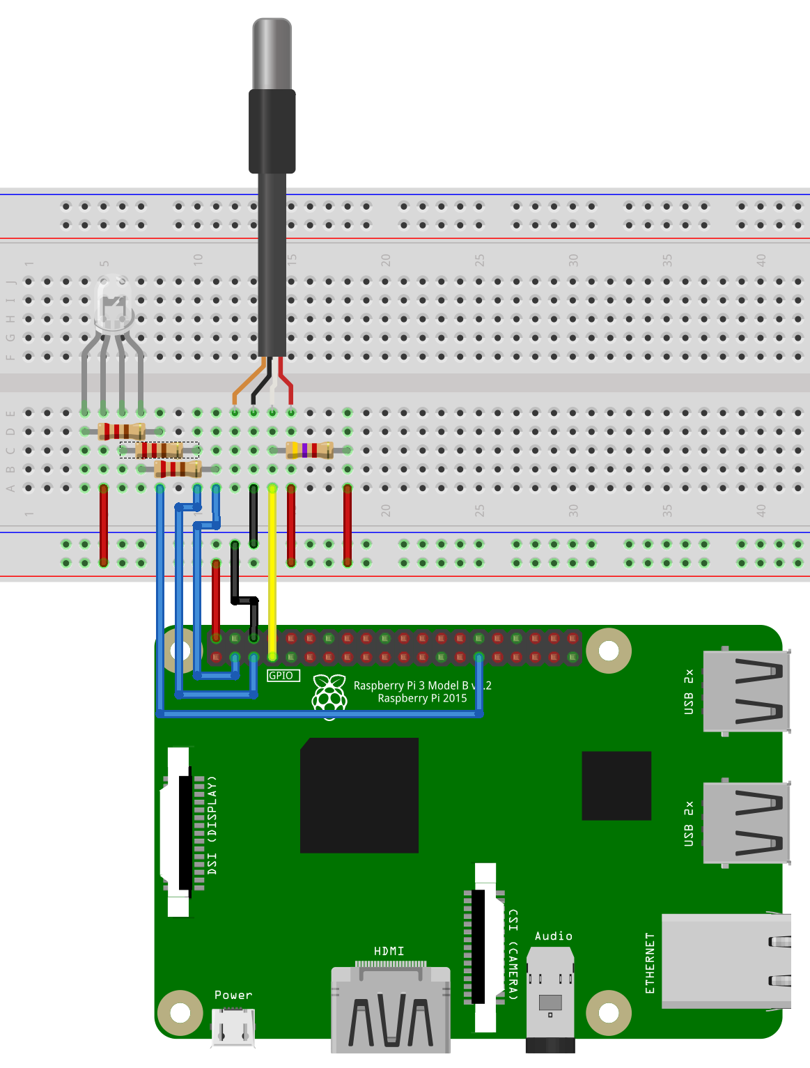
In the breadboard diagram the DS18B20 is shown with 4 wires, however most will just have 3. This is because it is showing the shield line as well, however we don't have to worry about that, so we're only using the Power, Ground and Data lines. Our sensor used a Yellow wire for the Data line, Red for Power, and Black for Ground. Because the wires on the DS18B20 sensor are fairly thin, you maye find it easier to use the terminal block to plug the sensor into the breadboard.
The colour of the data line may change, however the power and ground wires should always be Red and Black.
As mentioned above, the Raspberry Pi allows for 1 communication on GPIO pin 4. This will be the pin that the data line on our sensor connects to, make sure that you have the 4.7K resistor connected between the supply (Red) and data (Yellow) wires.
Because pin 4 is taken, our LEDs are going to output on GPIO pin 2 (Red), pin 3 (Green, and pin 5 (Blue). The RGB LED is common anode (the positive pin is common to the three colours), so we'll be using active low logic to turn the LEDs on; the LED will turn on when we output a low signal to it, and turn off when we output a high signal.
Lastly, we're using the 3.3V output to the positive rail of the breadboard, and the GND pin to the negative rail.
Finding The Device ID
As we mentioned before, every 1 wire device will have a factory programmed device ID. We can't change or assign this, so we need to find out what it is so that we can use it. To do this, open up a Terminal window and enter the following:
ls –l /sys/bus/w1/devices/

This command is just accessing the directory where the sensor IDs are kept, and listing all of the available ones. The DS18B20 will have an ID beginning with ’28-‘ followed by a series of numbers and letters. Make a note of the device ID (including the 28-) to use in our program (make a label for the sensor with its ID to save time for future projects as this ID won’t change).
Now that we have our device info, let’s use that data to do something!
The Code
Open up your Python 3 IDLE and create a new file called ‘temp-test.py’ (or something similar) and write this code in:
*As always, we recommend typing the code out yourself rather than copying it over as it will help you get a better feel for the language*
#import modules
import time
import RPi.GPIO as GPIO

#pin definitions
ledR = 2
ledG = 3
ledB = 5

#GPIO setup
GPIO.setmode(GPIO.BCM)
GPIO.setwarnings(False)
GPIO.setup(ledR, GPIO.OUT)
GPIO.setup(ledG, GPIO.OUT)
GPIO.setup(ledB, GPIO.OUT)

#set initial LED states
GPIO.output(ledR, 1)
GPIO.output(ledG, 1)
GPIO.output(ledB, 1)

#main loop
try:
    while 1:
        tempStore = open("/sys/bus/w1/devices/28-0315902106ff/w1_slave")	#change this number to the Device ID of your sensor
        data = tempStore.read()
        tempStore.close()
        tempData = data.split("\n")[1].split(" ")[9]
        temperature = float(tempData[2:])
        temperature = temperature/1000
        print temperature

        if temperature < 20:	#change this value to adjust the 'too cold' threshold
            GPIO.output(ledR, 1)
            GPIO.output(ledG, 1)
            GPIO.output(ledB, 0)

        if temperature > 20 and temperature < 24:	#change these values to adjust the 'comfortable' range
            GPIO.output(ledR, 1)
            GPIO.output(ledG, 0)
            GPIO.output(ledB, 1)

        if temperature > 24:	#change this value to adjust the 'too hot' threshold
            GPIO.output(ledR, 0)
            GPIO.output(ledG, 1)
            GPIO.output(ledB, 1)

        time.sleep(1)

except KeyboardInterrupt:
    GPIO.cleanup()
    print ("Program Exited Cleanly")
This program is designed to do the following:
- Import modules and setup pins.
- Retrieve the data being received by the DS18B20 from its device folder and process it into a user friendly format (Degrees Celcius).
- Compare the temperature with the 3 states: less than 20 Degrees (too cold = Blue), between 20 and 24 Degrees (comfortable = Green), and greater than 24 Degrees (too hot).
- Delay for a second. This is important as it takes about 750ms for the DS18B20 to take a stable reading, and it means we aren’t getting flooded with too much data.
- Loop steps 2-4 continually unless the program is exited using Ctrl + C.
*Make sure that you have replaced the Device ID in the code with the unique Device ID for your sensor*
Go to the 'Run' menu, and click 'Run module', save the file and it will run your program in the Python shell. The current temperature will print to the console as well if you want to see the exact temperature. Being Australians, anything below 20 Degrees is considered freezing, so that is definitely too cold, however feel free to adjust the temperature thresholds to suit whatever environment you are testing.
And there you have it folks, now you know how to use the 1 wire interface on the Raspberry Pi and use a temperature sensor to create a simple thermometer. Check out the tutorials section for more great Raspberry Pi tutorials.

