Introduction
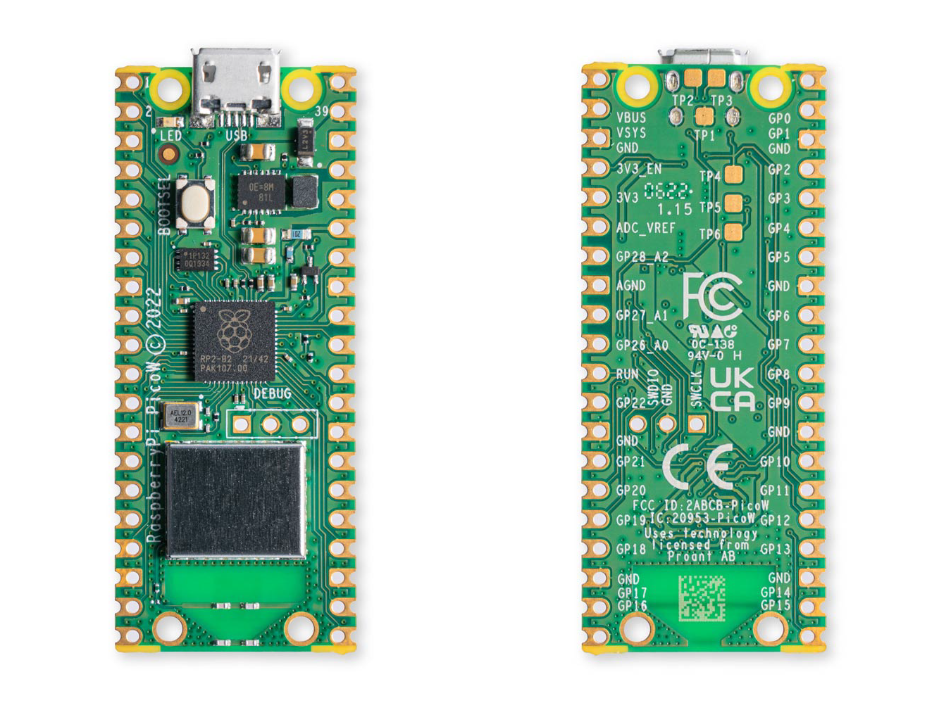
Let’s take a look at the Raspberry Pi Pico W - a WiFi-enabled development board from Raspberry Pi. This overview article will explore the Pico W features and specifications. As always, there are additional resources at the bottom of the article.
The Pico W is an affordable development board, featuring a powerful RP2040 processor and wireless connectivity. It’s based on the original Raspberry Pi Pico, so the 40 external pins on a Pico W are pin-for-pin compatible with the original Pico. That means most projects can be transferred from a Pico to a Pico W without modifying code.

Specifications
Processor: RP2040 (dual ARM Coretex-M0+ clocked at 133MHz; 256KB RAM; 30 GPIO pins
Flash: 2MB QPSI to store code and data
Wireless: Infineon CYW43439 supports IEEE 802.11 b/g/n wireless LAN and Bluetooth 5.2. At the time of launch, only wireless LAN is supported.
On-board user LED: connected to WL_GPIO0
Dimensions: 21mm(W) x 51.3mm(L) x 3.9mm(H) (or 12.9mm (H) for “H” models)
Weight: 3g (Pico), 4g (Pico W), 6g (Pico H and Pico WH)
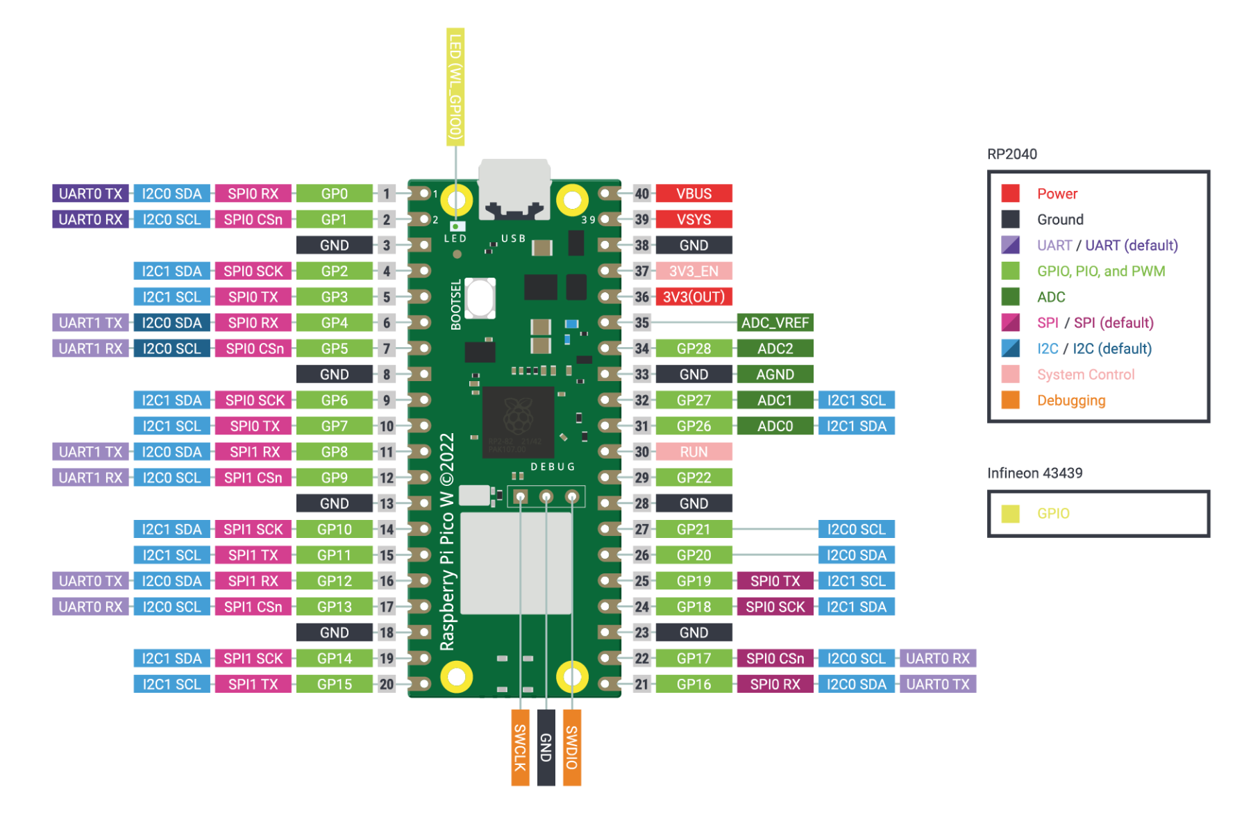
Pinout and Peripherals
The Pico W breaks out 26 GPIO for the user. GPIO0 to 22 are digital-only. GPIO26 to 28 can be used as digital GPIO or ADC inputs (selected in software). It's important to note that the Pico W I/O voltage is fixed at 3.3V (do not use in 5V circuits).
All the usual peripherals are included, and most conveniently accessible from most pin groups thanks to the "crossbar" bus fabric. There are:
- 2x UART
- 2x SPI SPI - 2 Independent buses
- 2x I2C
- 16x PWM channels
A user-LED is also provided and driven by the wireless interface. Access this LED in code using WL_GPIO0.
Some RP2040 GPIO are used for internal board functions:
- GPIO29 (Input/Output) wireless SPI CLK/ADC mode (ADC3) measures VSYS/3
- GPIO25 SPI CS (Output) when high also enables GPIO29 ADC pin to read VSYS
- GPIO24 (Input/Output) wireless SPI data / IRQ
- GPIO23 (Output) wireless power-on signal
- WL_GPIO2 – (Input) VBUS sense. HIGH when VBUS is present
- WL_GPIO1 – (Output) Controls onboard SMPS Power Save pin
- WL_GPIO0 – (Output) Controls user LED. Update: you can control this led by initialising the pin as: Pin("LED", Pin.OUT)
Wireless Interface
The Pico W features an on-board 2.4GHz wireless interface (Infineon CYW43439, datasheet) connected via SPI to the RP2040. The antenna is on board and should be kept in free space for best performance – don’t put metal under or close by the antenna.
Three GPIO pins from the CYW43439 are shared with other board functions and can be accessed via the SDK as:
- WL_GPIO2 (Input) VBUS sense. HIGH when VBUS is present
- WL_GPIO1 – (Output) Controls onboard SMPS Power Save pin
- WL_GPIO0 – (Output) Controls user LED
How to power your Pico W
The easiest way to power (and program!) your Pico W is via the micro-USB connector from a 5V USB supply like a computer USB port or power adapter.
External power can be supplied to VSYS, which will accept 1.8-5.5V DC. This wide range makes the Pico W easy to power from a battery source like AA / AAA packs or a single-cell LiPo. If you intend to power the Pico W externally like this and connect via USB you will need to power VSYS through a Schottky diode. This prevents USB power feeding out VSYS and into the battery - which would likely cause some damage to the battery. Check Chapter 3 of the datasheet for more information.
How is the Pico W programmed?
The on-board RP2040 is most commonly programmed using MicroPython – a powerful and simple interpreted language. There’s also an Arduino port for the RP2040, so it may be programmed in Arduino (C++) if you prefer.
Conclusion
The Raspberry Pi Pico W is a formidable development platform - plenty of GPIO, wireless connectivity and support for MicroPython - one of the fastest-growing programming languages - make the Pico W an obvious choice for wireless projects. If you'd like to learn more, see the additional resources linked below.

