In this guide, we will be taking our Makera Carvera skills one step further by carving out a 3D topographical map - a highly detailed physical model of any location you like. We will be taking a look at the theory behind different milling bits, how to set up both roughing and finishing passes in MakeraCAM, and how to safely secure your final piece by adding holding tabs. This is our second getting-started tutorial, and is designed to build directly off the concepts we learned in our previous 2D cutting guide. If you haven't completed that first project yet, you might be missing some important skills we covered there, so it's worth checking out first!
Let's get right into it!
Setting up our Stock and Model
Starting off, let's choose some stock! We are going to be using some soft pine wood for our piece, but if you have a spare block of brass, aluminium, or even ABS plastic, feel free to use that instead. The idea here is that by the end of this guide, you will be able to choose the correct settings for whatever material you decide to carve.
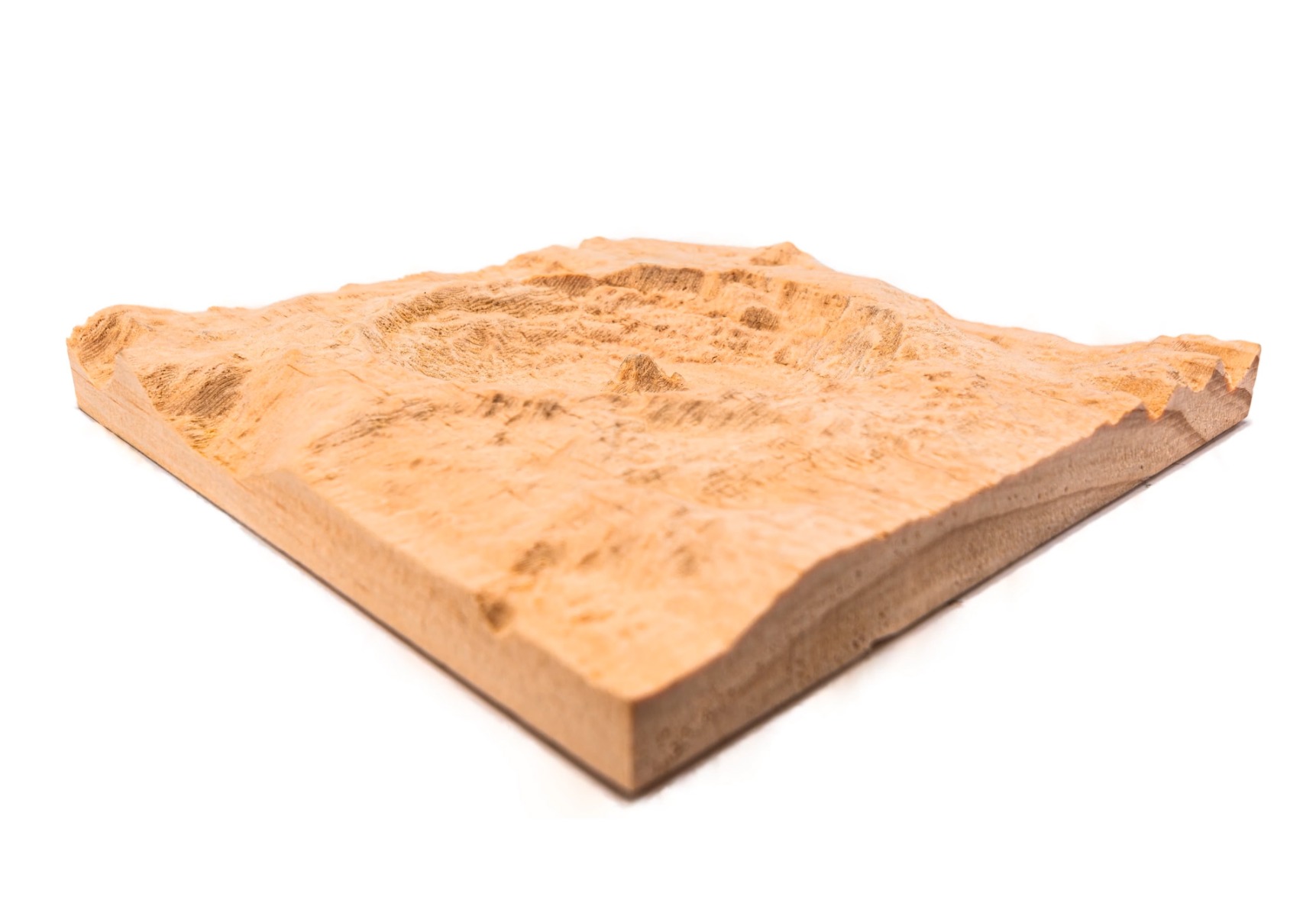
For our 3D model, we are going to use the Tycho crater on the moon, which features some absolutely wonderful topographical details. We have scaled this model to a few different sizes to choose from, depending on the size of stock you have. If you are cutting metal, it may be wise to choose a smaller model as the job may take a very long time to complete. The largest model cut on softwood (a quick material to cut), takes 6 to 7 hours. Engraving is a very slow process for CNC machines. Also, feel free to scale these even smaller if needed!
You can download the model designed to be used with the following sizes of stock:
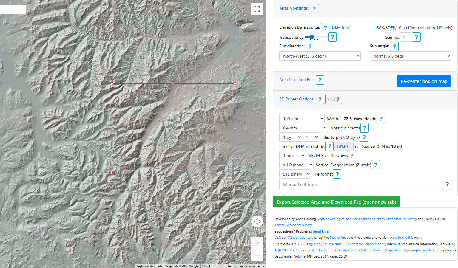
If you wish to engrave something that is not the moon, there are plenty of free online terrain to STL generators like touchterrain. There is a heap of dials and settings to play with to get a good result, but it will let you turn any place on earth into a 3d topographical model. Here are helpful things we found when using it:
- Elevation data source: You will need to find a data source with height data for your chosen location. You may have multiple options so choose the best one!
- Nozzle Diameter: This tool is largely designed for 3D printers, but if you choose the CNC high detail option, you will get the best results for milling.
- Vertical Exaggeration: Depending how large your selected area is, you may need to exaggerate the z-axis to make mountains appear taller, and valleys a little lower. Changing this from 1x to 1.5x can have a very noticable effect!
Alrighty, let's go ahead and open up MakeraCAM and CAM this thing out. We are going to select the 3 Axis workspace again, and as always, start by punching in your stock’s dimensions and material type. We are going to be using softwood and a 170x170x20 bit of stock, so change it to your selection.
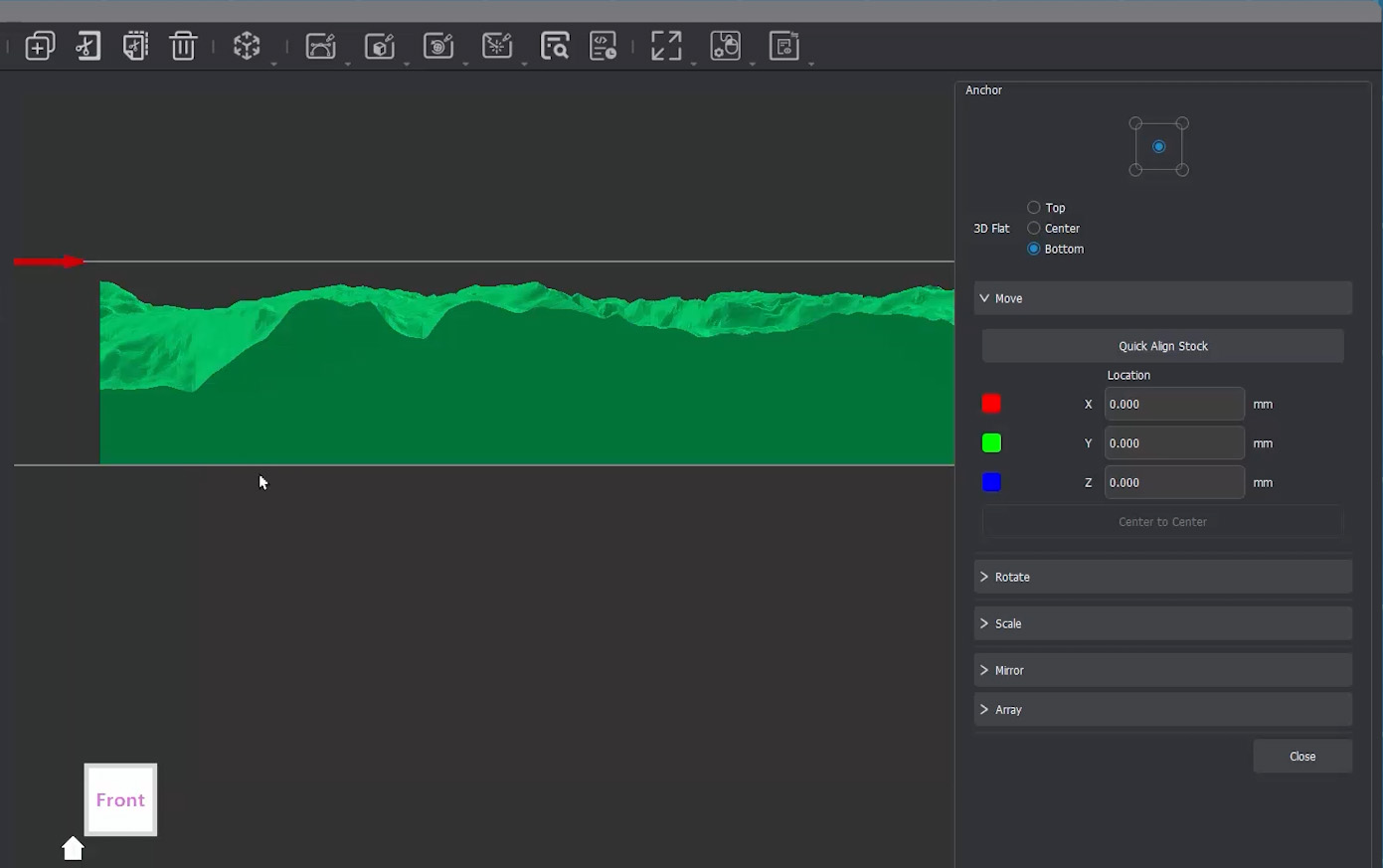
Next, we will import our 3D model and move it nicely into the centre of our stock. Now, we want to ensure that our model is sitting securely on the very bottom of our stock. To do this, open the transform menu from the top bar, select move, and then under the 3D flat section, select bottom. Then hit the Quick Align Stock button, and your piece should centre itself while sitting nicely and flat on the bottom of your stock!
Also, something critical to check: ensure that you have a safe margin around your stock for clamps! The models we provided will give you a 10mm wide rim around the edge just to give us some safe clamping room. So, while we have a 170mm square piece of wood, our actual crater model is only 150mm wide. It's a similar story for the smaller alternative models provided.
Now, unlike our 2D ice tray, we are going to need three separate cuts to make this piece:
- Roughing Cut: This is going to use a big milling bit to remove a lot of material very quickly. It will give us the general shape of our model and get us close to the surface of itl, but it won’t engrave much detail. Think of this as getting us 90% of the way there.
- Finishing Pass: This is where we get our very small engraving bit and carve out all the tiny details on the surface of our model. This finish pass does the final 10% of the work where all the details are.
- Contour Cut: Our third and final cut will be to actually cut our finished model completely free from the surrounding stock. Very straightforward.
Ready to set these up? Let's dive into it!
Roughing Pass and a Bit of Bit Theory
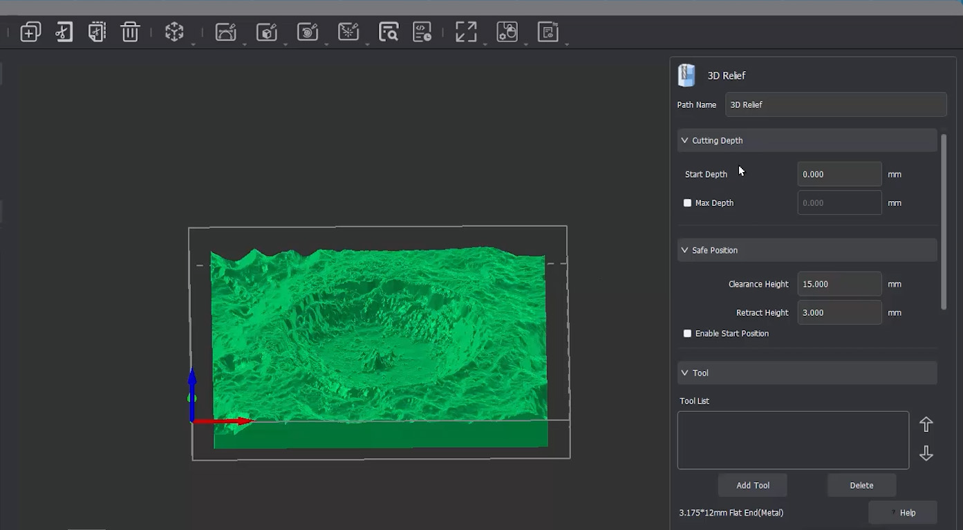
So, let's start with our roughing cut by selecting 3D Relief under the 3D top menu. We can leave our cutting depths alone for this operation. Just ensure we start cutting at 0mm, which is the top of our material. Our stock is perfectly flat on top, so our safe positions won’t need to be touched either. Let's go ahead and select a milling bit.
While we are in the tool menu looking at all these options, it’s probably a good time to talk about a bit of "bit theory"!
- Flute Bits (End Mills): These are our absolute bread and butter and are the bits you will be using the most. The main things you need to worry about are the width (wider removes more material quickly, but leaves less detail), the effective length (the actual length of the cutting edge), and the number of flutes. The Carvera bits are single-flute, meaning the tip has one sharp cutting edge. Why single-flute? Long story short, it is much more appropriate for the power of this machine, it gives cleaner cuts, and vastly helps with "chip extraction" (clearing away the cut pieces so they don't clog things up). The 3.175mm bit is likely going to be the most common width you'll use, but you can drop down to a thinner bit if you are doing smaller, more detailed parts.
- Metal vs. Non-Metal Bits: You'll notice flute and engraving bits are divided into these two categories. Metal bits feature a special coating to cut tough things like brass and aluminium, and they are crucially shorter in length. When cutting metal, you can run into "chatter"—a horrible screeching wobble that ruins your cut and damages the bit. The longer something is, the easier it is to bend, so the metal bits are shorter to help prevent this.
- Corn Bits: If you followed the standard Carvera setup manual, you actually have one of these sitting in tool slot 3 right now. The cutting edges literally look like little corn cobs, hence the name, and they are specifically designed for shredding through composite materials like carbon fibre and PCBs.
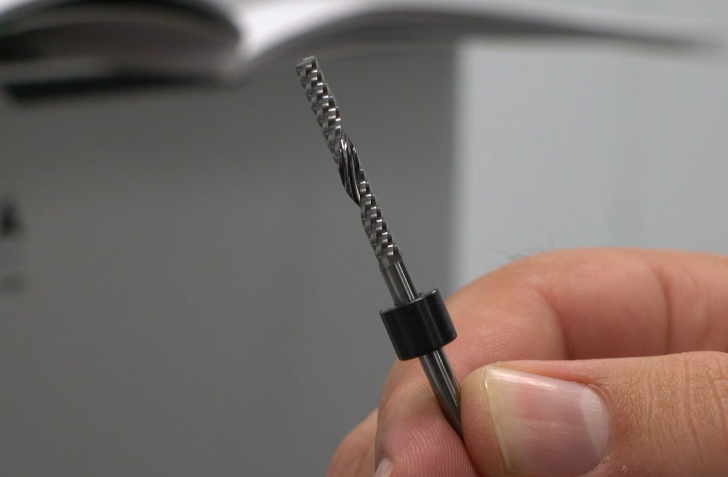
- Single Flute V-bits (Engraving): These are V-shaped bits that taper down to a very tiny flat tip, ranging from 0.1mm to 0.5mm wide. These are our highly detailed engraving bits, and exactly what we will use on our finishing pass.
- Chamfering Bits: Used to add chamfers (bevels) to your edges. Remember how our ice stamp tray in the previous guide had slightly sharp top edges? We could have run a chamfer bit over those edges to automatically file them down smoothly with a nice 45-degree chamfer.
- Ball Nose Bits: A type of engraving bit where the tip is shaped like a perfect little ball. This makes them highly suitable for carving and detailng curvy, sweeping, and round 3D geometries.
- Solder Mask Removal Bits: A very niche bit specific to PCB making; it simply scrapes away the top solder mask layer.
- Drill and Threading Bits: Drill bits simply drill straight holes of a given size, while threading bits carve standard-sized bolt threads directly into your material. Super handy to have in a machine with auto tool changing capabilities, and it saves having to hand tap them.
And that is all the bits! You will probably never use some of them, and not all of them came bundled with your machine, but it’s incredibly worth knowing what they are for and that they exist, so if you do need them, you can get one.
So, because we are cutting wood for this project, we will select the non-metal single flute bit. We will pick the 25mm one, which is the length currently loaded into our machine. Note: If you are cutting metal, you should pick the 12mm metal one that came with your machine instead. Just like we saw in the last video, the default speeds and feeds generated by MakeraCAM are perfectly fine. Just double-check that the bit you have selected matches the correct tool slot on your machine!
Now, let's look at the Processing Boundary. This setting is where we limit exactly what the machine is allowed to carve.
- If we select Material Boundary, the machine will try to remove absolutely everything inside the stock that isn’t our model. That includes the 10mm safety rim we left around the outside, which means it would carve right into our clamps! We definitely do not want that.
- If you want to get really funky in the future, you can actually import a 2D vector line and use that as the limit of your boundary! You could for example import a circle shape, and the machine would engrave the overlap between the circle and the 3d model.
- For this project, we will leave it on Model Boundary, because we only want to carve within the footprint of the crater model itself.
We are, however, going to increase the Boundary Offset by 0.25mm. The reason we do this is to make our roughing pass just slightly wider. This means that when we come in on our finishing pass, the bit isn't rubbing against the walls created by our roughing pass. This increase in size just gives us some breathing room on the next pass.
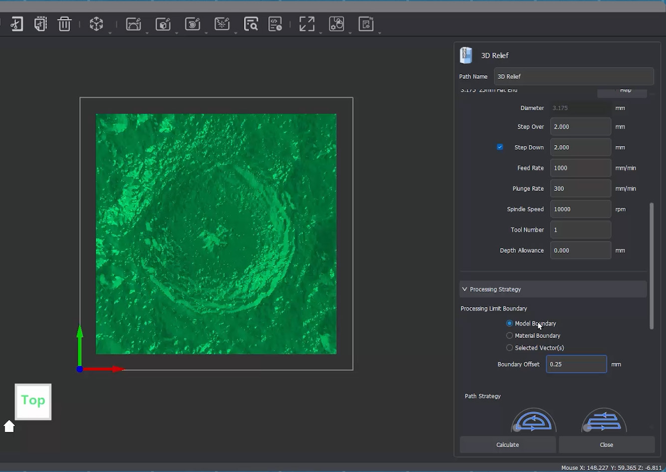
Under Path Strategy, we are going to select Parallel. When we were clearing out pockets in the last video, Offset was the better choice, but for 3D engraving, Parallel is usually the way to go. Though, if you are ever carving something perfectly round, Offset might actually look a bit better, just give it a go if you have the chance! We will also leave the cutting direction on Climb.
Now here is where we need to think about how we handle Tool Containment. This setting tells the machine how far we will let the bit wander from our boundary limit.
- Inside Boundary: This is us saying, "Hey, when you carve this thing, keep the entire tool inside the model. Do not let it leave the model for any reason."
- Outside Boundary: This says, "I will let you run the tool around the outside of the model, but the tool must always at least touch the edge of the model."
- On Boundary: This says, "I will let you move the exact centre of the tool right up to the edge of the model."
We are going to choose On Boundary. It might seem like a subtle difference now, but it will make a lot more sense when we look at the finishing pass in just a moment!
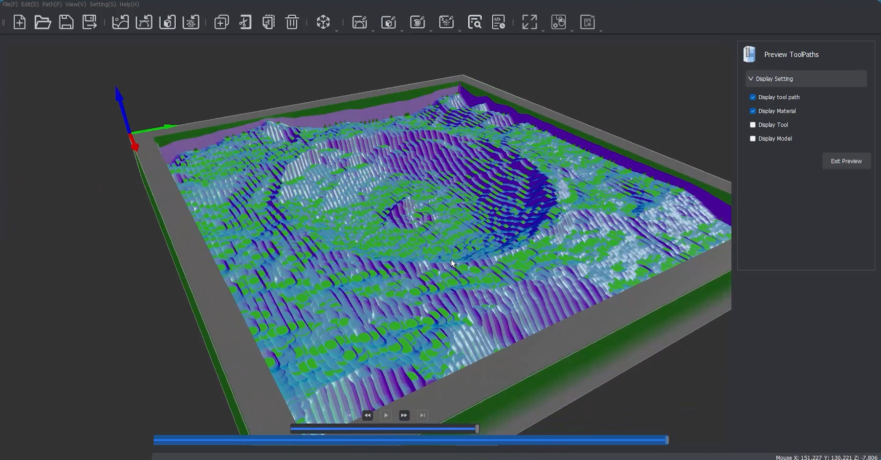
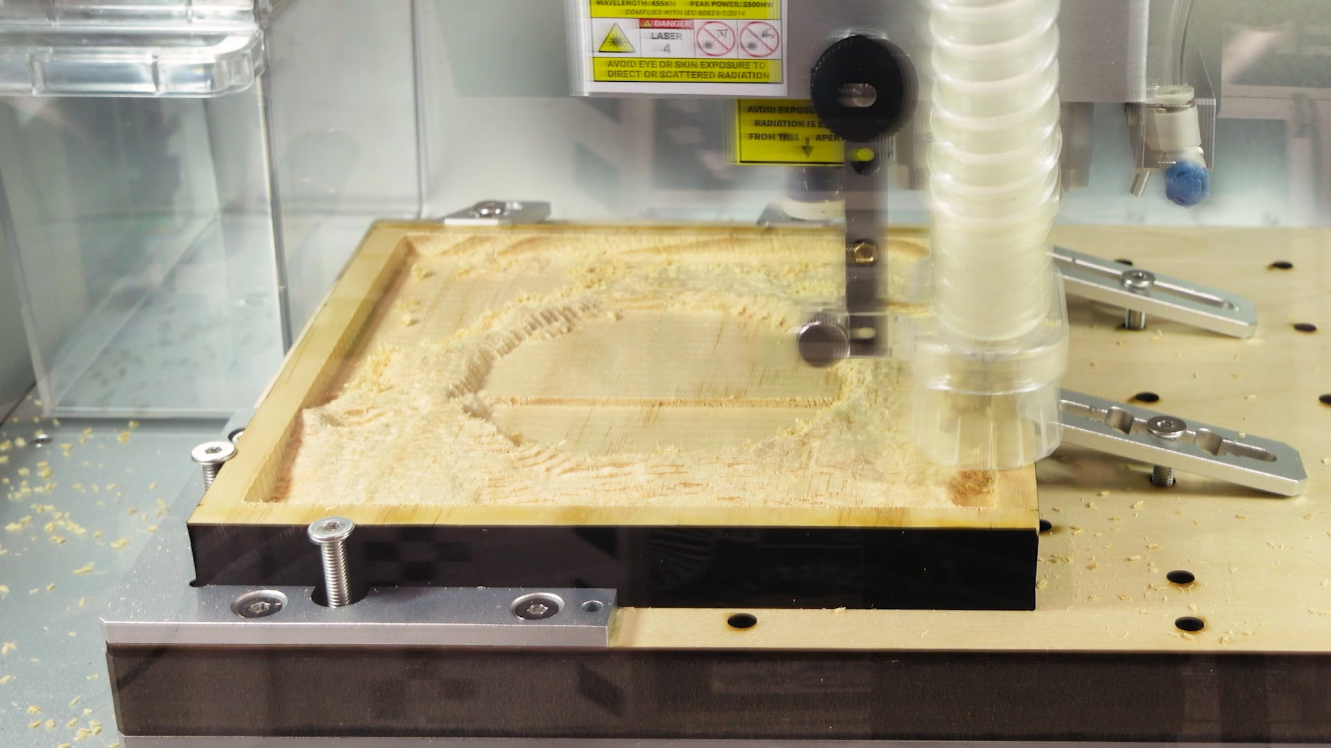
With all that set, we can hit Calculate and preview that toolpath. If everything looks good, you'll see in the simulation that we have 90% of our model cleared out, and you can really start to see the shape of our crater emerging!
Adding the Finishing Pass
Alrighty, that’s our roughing pass done! Now we can add our finishing pass to remove that final 10% and reveal all the intricate details of our crater.
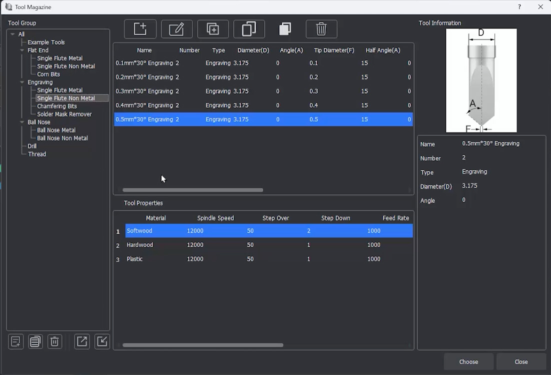
To do this, add a second 3D Relief job. The very first thing we need to do here is delete any tools that might already be in this new job's menu. It may try to auto-import the thick flute bit we just used, so make sure to remove it so the machine doesn't try to use it again. Now, we can add our engraving bit.
Looking at the Engraving V-bits menu, you'll notice they are all largely the same, with the major difference being the first size measurement (ranging from 0.1mm to 0.5mm). This number is the physical width of the tiny flat tip at the bottom of the V - it's the part that will actually be carving the details. The smaller this number is, the finer the detail you can achieve. However, a smaller tip also requires many more passes, which means your cutting job is going to take significantly longer.
Your Carvera likely only came with a 0.2mm V-bit for metal. So, unless you purchased extras, you will need to use that one if you are carving a metal block. For non-metals, it likely came with both 0.3mm and 0.5mm bits. Because we are using wood, we can use either of those non-metal bits. If you wanted finer 0.2mm detail on wood, you could absolutely use the metal bit! There is no harm in using a metal bit on softer non-metal materials.
I am going to select the 0.5mm bit. We have a large piece of stock here, and I really don’t want to turn this into a 24-hour job! Even with this "thicker" 0.5mm tip, this 170mm model will easily take 6 or 7 hours to carve. Engraving is a very long process on CNC mills.
Now this 0.5mm V-bit is not loaded into our machine, so we will ensure we put it into slot 5 before we begin cutting.
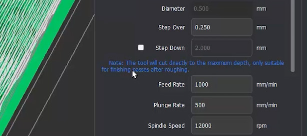
Now that our tool is locked in, we can set up the second cut. We can leave our feeds and speeds exactly as they are, but there is one absolutely crucial setting to change: we need to untick Step Down.
What this does is it tells our machine, "Hey, don't worry about milling away the material above the model layer by layer." It tells it to just do one single layer of removal right along the final surface of our 3D model. This makes perfect sense because we already removed all that bulk material above it with our roughing pass!
Unticking Step Down is the essential magic button that turns this into a finishing pass.
Next, ensure your Processing Boundary is set to Model, and ensure you set the Boundary Offset to 0mm. This explicitly makes the finishing pass slightly smaller than the roughing pass we set up earlier.
Now, let's revisit Tool Containment. The part of our V-bit that actually does the detailed engraving is the very tip, perfectly in the centre of the bit. Because of this, we want to ensure that the centre of our bit is allowed to reach the exact edge of our model.
- If we set containment to Inside Boundary, the software will stop the outer edge of the tool at the boundary, preventing the centre tip from ever reaching the edge of our model. No good!
- We could choose Outside Boundary, but that would tell the machine to mill a few millimetres past the model into our blank stock, wasting precious time.
- So instead, we select On Boundary. This lets the middle engraving tip of our bit perfectly kiss the edge of our model and go no further. There is a time and a place for the other containment options, but this is exactly why we use On Boundary here.
And with that, we can hit Calculate. Be patient here as with a detailed 3D finishing pass, there is a massive amount of math involved for the software to figure out the complex path, so it may take a good few minutes to fully calculate.
But once it does, you will be left with a very cool simulation to check out, which should reveal all the details of our topographical model!
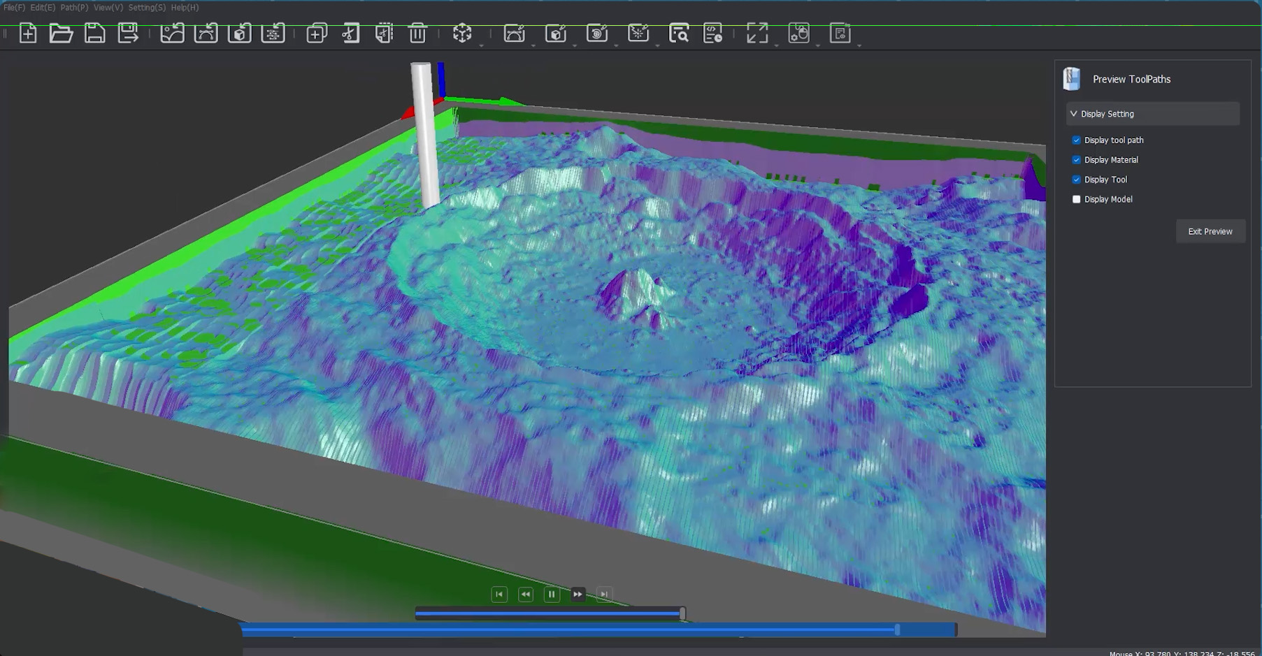
Adding the Countour and Tabs
The final operation we need to add to our project is the contour pass. This is the cut that will actually slice our finished 3D model completely free from the surrounding block of waste wood.
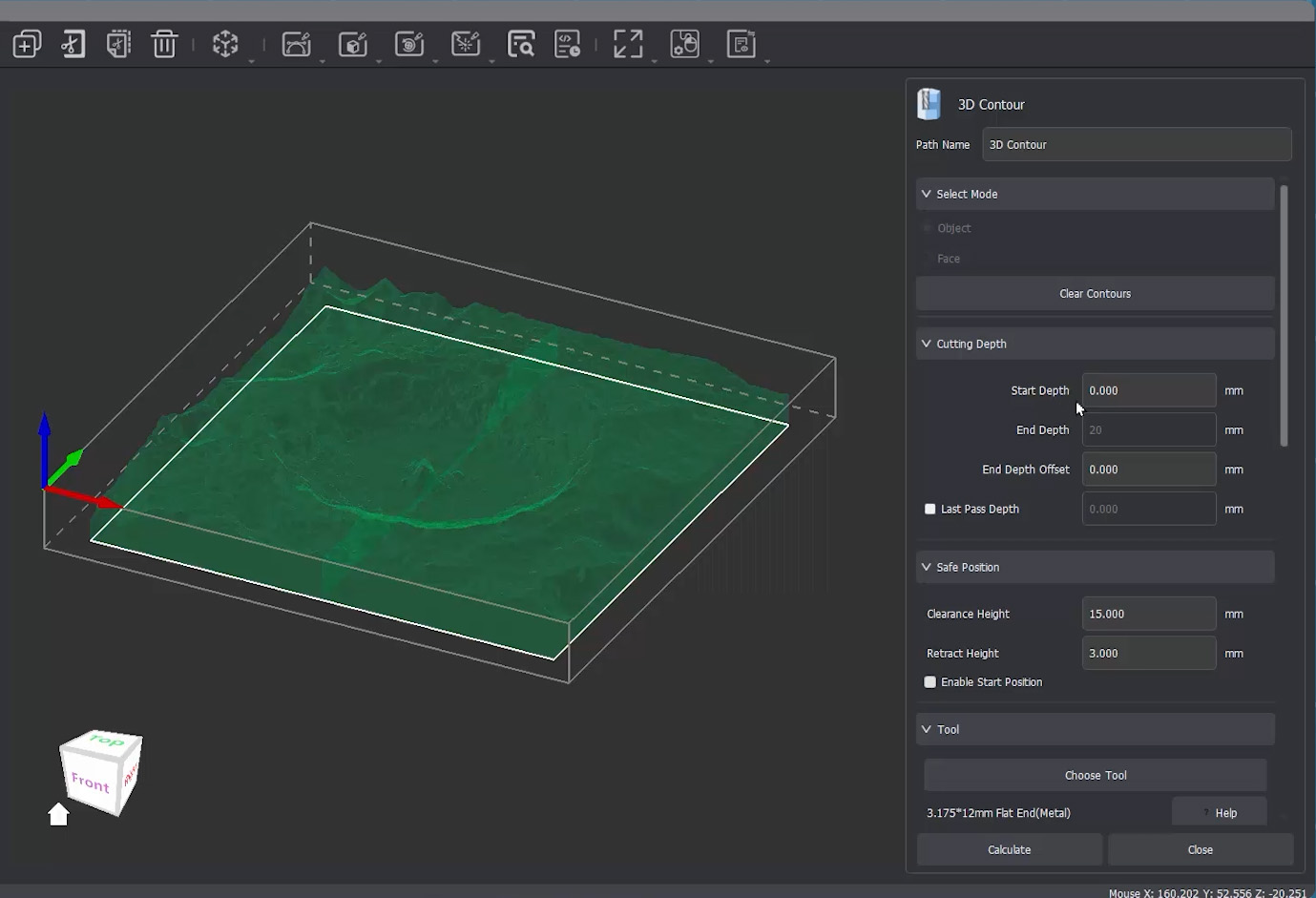
To do this, we will add a 3D Contour job which lives in the same top menu as the 3D relief.
First things first, we need to tell MakeraCAM exactly what it needs to cut around. Select your model, ensure the object option is selected, and then click Generate Contours. This makes the software analyze our complex 3D object and automatically trace a nice, flat 2D footprint shape around the base for our milling bit to follow.
Next, we will set up our Cutting Depth. We are going to keep the start depth right at 0mm (the top of our stock). We are, however, going to change the target depth to go 0.5mm deeper than our actual stock thickness. This slight overcut is a classic CNC trick to ensure the bit slices absolutely all the way through the bottom of the material, so we aren't left with a paper-thin layer of wood holding it together. To do this, set the "End Depth Offset" to 0.5mm.
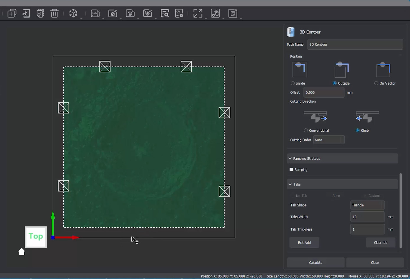
Under Tool, we are just going to select the exact same 25mm flute bit that we used for our roughing pass. Under Position we will just select Outside as this will cut out around our 3D model. The rest of the settings should stay on their defaults.
Now we get to add tabs! When we add a tab, we are telling the machine to intentionally not cut all the way through in a few specific spots. This leaves tiny bridges of material connecting our finished part to the securely clamped outer waste stock. If we didn't use tabs, the moment the bit completed its final cut, our loose model could catch the spinning router bit and be violently thrown across the machine. Tabs ensure the part won't move around or do anything silly. They are designed to be strong enough to securely hold your part in place against the forces of the spindle, but thin enough that you can easily slice them off by hand once the job is done.
To add a tab, select custom, and leave it on the default settings. However, you will need to add the tabs manually with the Tab button. Select the white outline of the boundary in your workspace (it will become a dotted line when selected), and hit the tab button to start adding tabs. You will then need to accurately select points on the white line to add the tab. It might be a good idea to leave one side without tabs. This will give you a nice, perfectly clean surface right off the bed as tab removal can create artifacts if you are not careful.
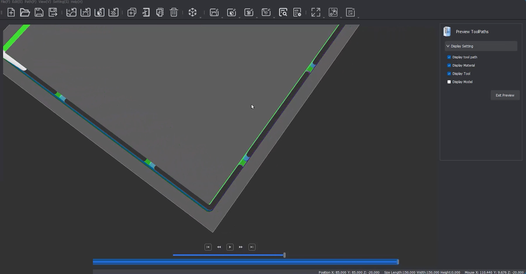
With our tabs placed, we can view our simulation once more and confirm that our contour has cut all the way through, and our tabs were generated correctly.
Exporting, Cutting, and Finishing Up
With our toolpaths completely set, we are just going to go ahead, export our G-code, and get it over to the machine!
The physical process of setting up and running this cut is going to be exactly the same as our 2D ice tray project, but with one major pre-flight check: we absolutely need to ensure that our physical tools are placed in the exact slots we assigned them to in MakeraCAM.
If you are using a brand-new bit straight from the Makera bit kits, you will need to use the included collar tool to press a plastic collar onto the shank of the bit. Without this little plastic ring, the Carvera's automatic tool-changing spindle cannot physically grab or hold onto the bit!
Open up your file in the Carvera Controller and do a quick visual check of the green toolpath lines to ensure everything looks correct.
When you go to start the G-code task, ensure your Work Origin offsets are set to 0,0. We can safely do this because we purposefully left that 10mm safety boundary in MakeraCAM specifically for our clamps to sit in.
Finally, double-check that Auto-Levelling is enabled (the default of a 5x5 grid should be plenty enough), and go ahead and hit run.
Now, sit back and watch the magic happen! The machine will automatically work its way through the heavy roughing pass, automatically swap over to the V-bit for the incredibly detailed finishing pass, and then do one final tool change to cut the model out from the stock.
Once the machine finishes and parks itself, remove your stock from the bed. You can use the small hand saw included with your Carvera to gently snip through those wooden holding tabs we added. After the part is free, just hit those tab spots with a bit of sandpaper to smooth them perfectly flush with the carved edge.
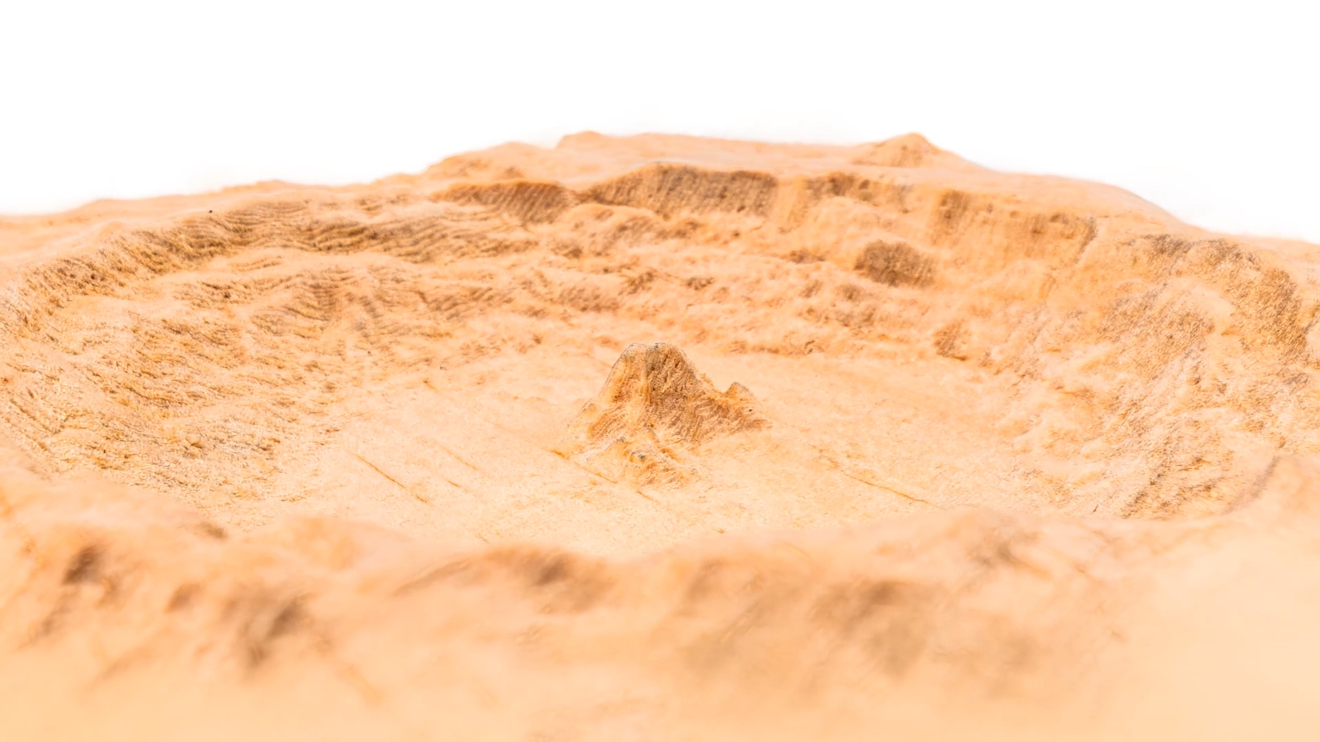
And there you have it—that is our final 3D topographical piece!
Fun fact: that mountain in the middle of the crater is a remnant from the meteor impact. When it hit the moon, there was so much energy that the surface of the moon turned to liquid rock! That mountain in the middle is the surface of the moon splashing back exactly the same way water does when you drop something in it. What an incredible artifact to capture in an engraving!
Where to From Here
And that is our final piece! Hopefully, this guide, along with our first 2D cutting tutorial, has given you the foundational skills and the confidence you need to go out and start making your own custom parts from scratch.
If you want to dive even deeper into the software, Makera has a fantastic, large collection of tutorials over on their YouTube channel. They cover almost every single specific tool you will find inside MakeraCAM, so if you ever get stuck trying to do something complex or niche, chances are they have a dedicated video guide for it ready to go.
Finally, if you make anything cool, carve out some funky terrain you want to share, or if you just need a hand troubleshooting anything we covered in this guide, feel free to post about it on our community forums (below is the post for this guide). We are all makers over there and are always happy to help.
Until next time, happy making!

