In this guide, we will be learning how to use the Makera Carvera to mill an ice stamp tray - a heavy piece of metal that imprints decorative patterns into a block of ice. We will be taking a look at what stock materials to choose, how to set up our 2D files and tool paths in MakeraCAM, and how to safely run your very first job on the machine. This is a getting-started tutorial, and is designed as sort of the first step someone might take after completing the example cutting projects included with your machine. If you haven't completed those yet, that is fine, but some of the skills covered in those projects will help here.
If you are from the video and chasing the vector design file, here you go!
Let's get right into it!
Why CNC and Choosing a Material
First of all, CNC milling is a subtractive manufacturing process. You start with a big block of raw material (which we call our stock) and the machine cuts away at it bit by bit until you are left with the shape you want. Compared to laser cutting or 3D printing (which are additive processes where you build things up), CNC milling is messy, it's loud, and it's a little wasteful in that you are turning a good chunk of your stock into metallic confetti. So, why would you want to do this?
Well, the biggest advantage is versatility. You can make parts out of pretty much anything, as long as it’s soft enough for the milling bit to cut. Materials like PVC cannot be laser cut because they release poisonous gas, and polycarbonate is a massive fire hazard under a laser. Milling these things, though? Perfectly fine and safe. And how about solid metals like aluminium and brass? Good luck trying to 3D print those on a standard desktop machine!
That versatility is exactly why we are going to mill a metal ice stamp tray. Machining soft metals is really the specialty for a machine like the Carvera, and it makes for a fantastic, easy first project.
So, the first step is choosing our stock. Most commercial ice stamp trays are made of brass because it has wonderful thermal properties (it can store a lot of heat) and is naturally anti-microbial. You can very happily use brass for this project, but there is a major catch:
If you use brass, you MUST ensure that it does not contain any lead. Many common machinable brass alloys contain lead to make them easier to work with. If you don’t have absolute confirmation that your brass is lead-free, or you don’t know the exact alloy, do not use it!
To play it completely safe, we are going to use Makera's 6061 aluminium, which is a known food-safe alloy of aluminium (as long as you don't use anything acidic on it, water is fine)!
Size-wise, the thickness of your material matters because we need enough thermal mass to actually melt the ice. You will want your block to be at least 5mm thick if you are using brass, and at least 8mm to 10mm thick if you are using aluminium (since aluminium doesn't hold quite as much thermal energy as brass). For our project, we are using a 100mm by 150mm block of 10mm thick 6061 aluminium.
If you want to follow along and learn, but not commit to a block of aluminium, this project can easily be done with a block of wood! You just obviously won't be able to melt ice with it. If you want to do a practice run before committing to aluminium, wood is also a good idea!
Sourcing the Design File
Now that we know the size of stock we are working with, we can get an appropriate design file to cut. We are going to be using MakeraCAM, which is the software that generates the instructions for our machine which we call G-code. MakeraCAM accepts either a 2d vector, or a 3d model. In this guide, we are just going to be using a 2d vector. In the sequel to this guide, we will be doing some 3d engraving.
We have a file ready to go for a 100 by 150 mm piece of stock (any thickness). If you wish to use your own custom design, you are more than able to! Using a vector design software like Adobe Illustrator, Inkscape (a free option), or even using CAD software and exporting the face as a vector, you can draw your own custom ice stamp. Just follow these guidelines:
- You will need to draw enclosed shapes. The mill will be cutting the area out of these shapes.
- The shapes will need to be at least 3.175mm wide. This is how wide our cutting bit is. If you make a 2.5mm wide shape, the bit won't be able to fit in there and cut it. Also know that the bit is big and round, you will not be able to make a sharp corner as the bit won't be able to get in there to cut it out.
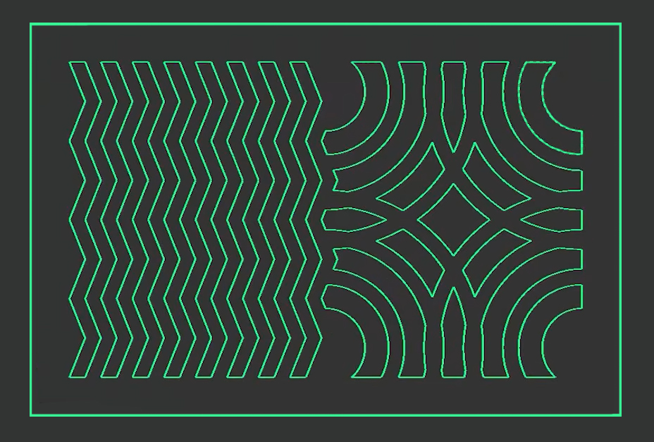
- Leave a small gap around the outside of your design. We need a small rim to clamp our stock to the machine - 10mm is very safe. In the image on the right, you will see how our design leaves this gap nicely.
Setting up MakeraCAM
If you haven’t already, go ahead and install MakeraCAM. Now, this is not free software, but you do get a copy included with the purchase of your machine. When you first open it, you will be prompted to enter some details through the retailer you purchased it from. If you bought it through us or another retailer that isn't listed, you'll just need to contact Makera via email with your machine's serial number and proof of purchase, and they will get you access. They are usually pretty quick with this, and you can grab a 15-day free trial in the meantime by just punching in any old email address.
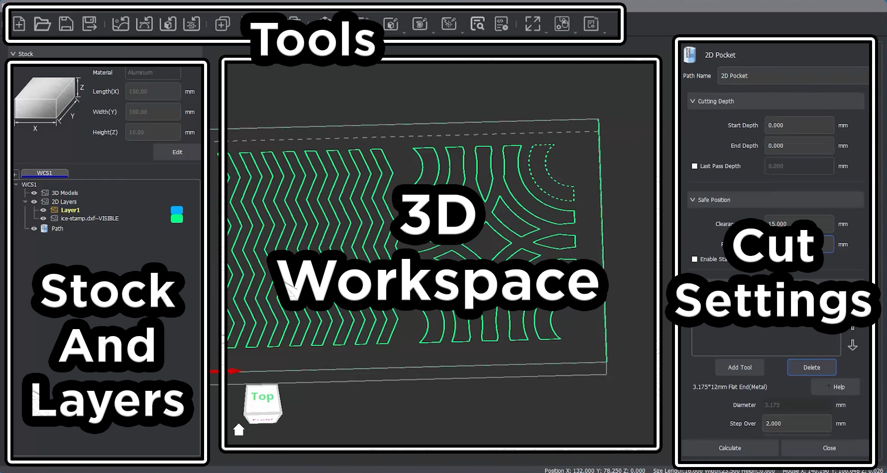
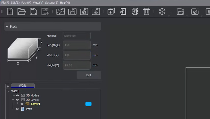
We are going to open MakeraCAM and select the 3D Relief workspace. The 4th axis option is for when we are using the 4th axis accessory. Let's quickly get the lay of the land here: the large central window is our 3D visual workspace where we will see our stock and our design. The menu at the top is where we have all our tools to create cuts, preview cuts, and export our G-code. On the left side is your stock settings as well as all the layers of cuts you create. And when you start creating a cut, the window on the right will appear with all the settings we will be changing to set up the cut.
First things first, we need to set up our stock. We do this by selecting the material we are using and punching in its physical dimensions into the setup menu.
You will need to specify the material, as well as the dimensions of your material. The image on the right shows the settings for our piece of 6061 aluminium.
In the top menu bar, you will find the button to import 2d model, select it and import the vector file you downloaded or drew.
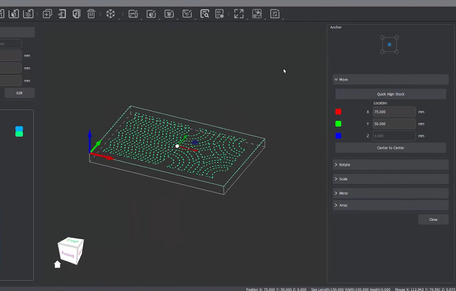
Chances are, it will have been imported not centred on our stock, so we will need to fix that! To ensure it is perfectly centred, drag and highlight the entire vector. Then in the top bar, select the transform menu (it should look like a cube), and select move. The keyboard shortcut for this is to simply press the "M" Key.
In this menu, you can manually punch in the coordinates to centre your design on your stock, or you can just press the "quick align stock" button, which often does a pretty good job.
Looking at our workspace, we can see all the lines we will be cutting. The area formed by those inner vector lines is what we will be milling out. You might notice an outer bounding line on the edge of the stock. This is just a reference line we used in the vector design process. Avoid selecting this or trying to cut along it as you might get some very wrong results!
Creating a Pocket Cut
Now, unlike the slicer software for a 3D printer (which does almost everything automatically) there is a bit of manual work required here to produce our G-code - the actual text file of machine instructions that will tell our Carvera how to move and cut out our piece. We have the shape we want, but we need to explicitly tell the software how we want it to cut along our lines.
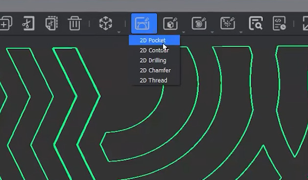
Under the 2D Cutting Operations in the top menu bar, you will find our absolute bread and butter cutting operations:
- Pockets: These will machine away everything inside a selected area. It completely hollows out the entire inner section of the selected shape.
- Contours: These will just cut a path along the edge of the line and leave the material in the middle intact.
Because we want to completely remove all the material inside these shapes to create our stamp indentations, we will hit Pocket.
Alright, after hitting Pocket, you are going to be greeted by a wall of settings. The beauty here is that you don’t need to touch a lot of these, as MakeraCAM will automatically give you appropriate default values. Let's go through each section to understand what it does, and what we should maybe change.
- Cutting Depth. This is simply how deep we want to create this cut into our material. We will set the start depth to 0mm (the top surface of our stock), and we are going to make our cuts 4mm deep by entering 4mm by entering it into end depth. If you want to save some time, you can go 3mm deep instead, which will reduce your overall cutting time by about 25%. A depth of 3mm or 4mm should be plenty for our ice tray, so pick your poison!
- Safe Position. This tells the machine how high to lift the milling bit upwards when it moves between cuts. We can leave this at the default for now, but as a quick analogy: let's say our stock had a weird hill in the middle of it. If the machine moved the bit from one side of our stock to the other, it might crash into the hill and break something. By changing the safe position, we can tell the machine to raise the bit higher to avoid it. This is rarely used as we often mill flat things, but its handy to know.
- Tools. This is where we select the tool and the settings that we want to use to perform this cut. There are quite a few options in the library, representing the bits within the Makera ecosystem. For this type of metal cut, we are going to select the Single Flute, then choose the 3.175mm wide and 12mm long metal bit. If you set your machine up according to the standard instructions, this bit was put into tool Slot 4. Under the tool list is a whole heap of tool settings. We aren’t going to tweak these, because if we push the machine too hard, we risk breaking our bit. The default settings are incredibly safe as they are on the slower side. While they could possibly be bumped up a little, this slower speed guarantees us some nice, clean cutting results. However, it is definitely worth knowing what each of these settings means for your future projects. Let's quickly go under the hood:
- Step Over: When your bit cuts through your stock, it's going to cut it back and forth in lines (or passes). When it reaches the end of a pass, it moves over a little bit and comes back the other way. Step over is exactly how much it moves over between each pass. If we had a 2mm wide bit, and we had 1mm of step over, our bit would cut the next path half overlapping the previous path. Our bit is 3.175mm wide, and our step over is 2mm. This means there will be some overlap between cuts, which is exactly what you want for a clean clear-out.
- Step Down: This is the same idea, but in the vertical direction. The machine is going to cut out these pockets layer by layer. Step down dictates how thick each of those layers is - essentially, how much material you want to shave off the top in each downward pass.
- Feed Rate: How fast the bit moves through the material in the horizontal (X and Y) direction. Imagine driving a mini car on the top of your stock. The feed rate is your speed limit.
- Plunge Rate: This is another speed limit, but in the vertical direction. It's how fast the bit is shoved downwards (the Z direction) into your stock. This is almost always lower than your feed rate because plunging down is harder on the tool, than moving side to side.
- Spindle Speed: Simply how fast the milling bit will be spun by the motor.
- Tool Number: The slot that the bit is loaded into on your machine. Since we set it up in slot 4, we will leave this as 4.
- Path Strategy. This dictates the pattern the machine will use to remove the area. We will leave it on Offset to give us smoother edge cuts, and we will leave the Cutting Direction on Climb as well.
- Ramping. Normally, when your machine starts a cut, it plunges straight down and then moves across. Ramping tells your machine to go down and across at the same time (like walking down a ramp). Really simple, enable if you are cutting metal, disable if you wish if you are cutting wood. We are going to enable it here, and leave it on the defaults.
Now that is a lot of settings to remeber for one cut, but thankfully we don't need to modify many, and the defaults are often good enough. Ensure you still have your vector selected (it will be a dashed line) and hit Calculate. MakeraCAM is now going to run the math and figure out exactly how to move the milling bit to cut out our part according to all the settings we just locked in!
In your 3d model preview area, you should see a series of white lines. These lines show where the tip of your mill bit will be passing through to cut out your part. A handy thing to do is to preview the tool path with the cutting simulation button in the top menu. This will show you a simulation of what the job will look like so you can double-check that the cut is performed the way you want it to, and that the part will look the way you imagined it would.
If you are happy with it, exit the preview and hit the export button in the top menu to export the G-code for this job. It should save as a .nc format (don't confuse it with saving the makeraCAM project file)!
Running the Job
Head to your Carvera, and bring your G-code files with you!
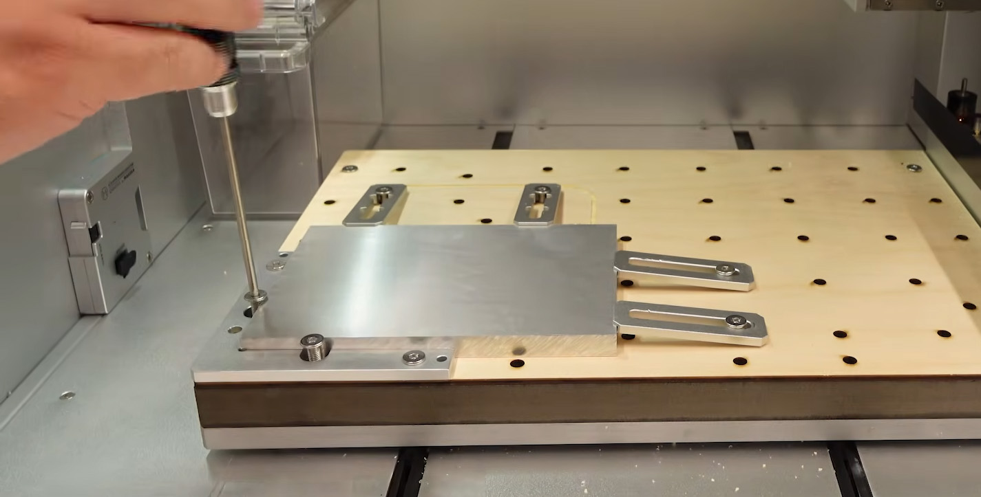
Before we touch the machine, we need to talk about safety. This can be a dangerous machine, but as long as you respect it, you will have a safe and fun time.
- Use the E-Stop: Whenever you stick your hand into the machine or anywhere near the spindle, ensure the machine is not running any G-code and that the emergency stop (E-stop) button is firmly pressed. This machine does not know the difference between metal and flesh, nor does it care.
- Eye Protection and Lid: The spinning bit is producing a massive amount of force. There is always the risk that a bit snaps and flies off at 100km/h, or your stock gets ripped up and thrown. Ensure the safety lid is down and you are wearing safety glasses when cutting.
- The Laser Module: While we aren't using it for this project, the Carvera features a 2.5-watt laser module for engraving. When active, this is a Class 4 laser and can cause instant, permanent eye damage. Keep that in mind for future projects!
- Lid Interlocks: By default, this machine will likely keep working even if you open the lid during a cut (the interlock is disabled out of the box). If you want to change this behaviour to automatically pause when opened, you can find that option under your machine settings.
When this machine cuts, it is going to try to rip your stock off the bed and throw it. This is why we need to firmly clamp it down. There isn’t really one "correct" way to arrange your clamps, as long as you have enough of them to hold the piece completely rigid. The bolts don’t need to be comically tight, just firm enough to hold everything securely.
Ensure that your stock is sitting perfectly flush inside your corner anchor bracket. This bracket is how your machine knows exactly where your stock is physically sitting on the bed. If you ever need to mount your stock somewhere other than this corner in the future, you will need to use the included wireless probe kit to manually tell the machine where the stock is located. We won't worry about that today.
Now, let's open up the Carvera Controller software on your computer. You should have set this up when following the demo projects, but if not, you'll need to install it now.
First things first, let's connect to our machine. We have ours connected directly via USB, so we will simply select its COM port to connect through the menu in the top left.
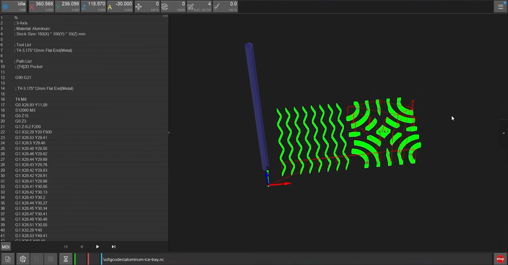
Next, let's get our G-code file loaded in. Select Upload file (very bottom left button), navigate to where you saved your .nc file on your computer, select it, and then hit Upload and Select. It may take a couple of minutes for the file to fully transfer over to the machine. Once that is complete, you should see your tool paths represented as green lines on the screen, alongside all the raw G-code commands scrolling on the left.
In the bottom left, you will find a button to "start G-code tasks". Select it, and a job menu will appear with the following settings:
- Work Origin: This is just another name for where the corner of our stock is sitting. We will tell the machine it is sitting in Anchor 1. Because we made sure the stock is sitting perfectly flush in that bracket, we will set the offsets to 0 and 0. Back in MakeraCAM, we purposely left a gap between where we are cutting and the edge of our stock. Because of this gap, we don’t have to worry about the bit accidentally cutting into a clamp. If you didn't leave enough room in your design, you would increase these offsets here to give your clamps a bit more physical clearance.
- Scan Margin: We absolutely want to enable this. When the job starts, the machine will pick up the wireless probe and use its little laser pointer to trace out the edges of our cut on our stock. This is incredibly helpful for double checking that our tool isn't going to cut into our clamps. This is not the engraving laser by the way, just a little safe laser pointer.
- Auto Leveling: Select this and leave it on the preset 5 by 5 grid. This tells the machine to use the wireless probe to sample a 5 by 5 grid of points on our stock to see how flat it is, and to automatically account for any slight bends in our material.
- Vacuum System: In the top right of this menu is the vaccuum system button. If you are using the Carvera’s inbuilt vacuum system, enable it here. If you are using something external, remember to turn on your external dust extractor.
IMPORTANT: EMPTY YOUR VACUUM BEFORE CUTTING METAL! If you have something like wood dust sitting inside your vacuum system (which is highly flammable and potentially explosive), you absolutely do not want to throw blisteringly hot, metal fragments in with it. That is a possible fire hazard and an accident waiting to happen.
With all of that double-checked, we can hit Run.
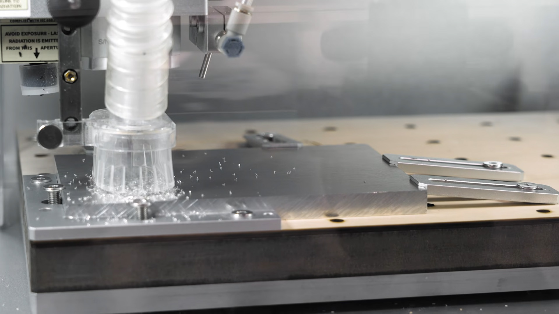
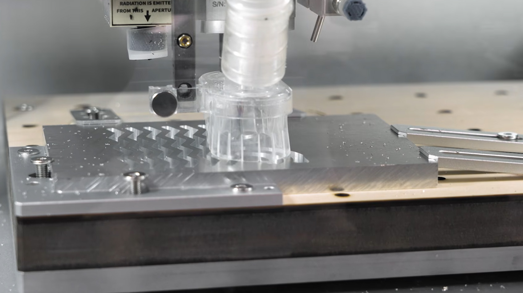
When our job officially starts, the machine will pick up the wireless probe and scan our margin. Always watch this process. It is your final visual check to ensure there are no clamps sitting inside the cutting area. Once the margin is clear, it will probe the 5x5 grid to level the piece, automatically grab the metal single-flute bit from slot 4, and begin cutting.
Because cutting metal requires shaving off very thin layers to prevent breaking the bit, this process should take a little over 2 hours. For comparison, if we were cutting this exact same design out of wood, it would only take about 20 to 30 minutes! This is because we can cut off much thicker layers with softwood.
You can now sit back and let the Carvera do its thing. However, please ensure that you are actively monitoring the cut.
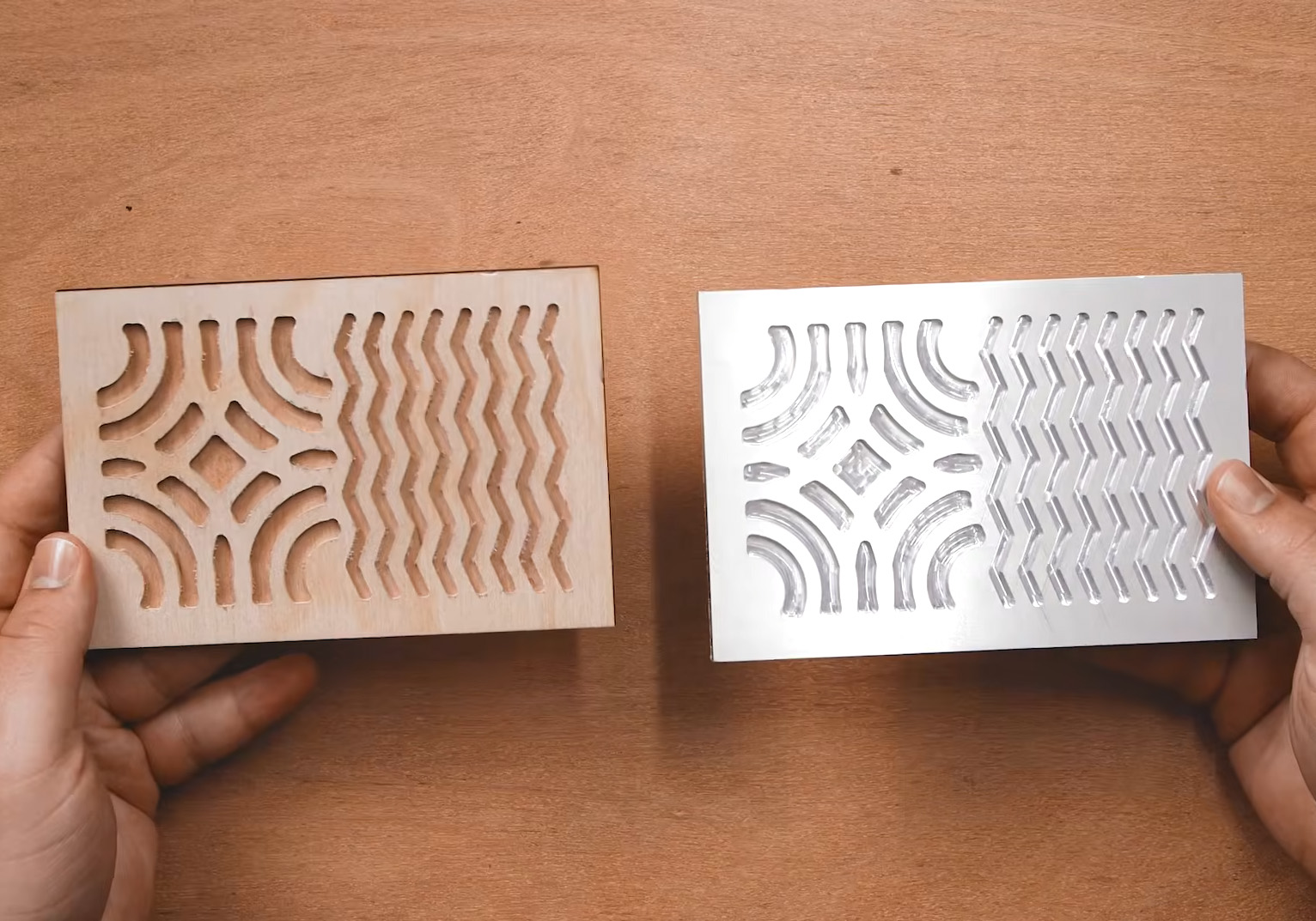
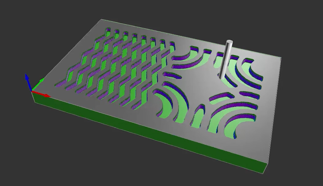
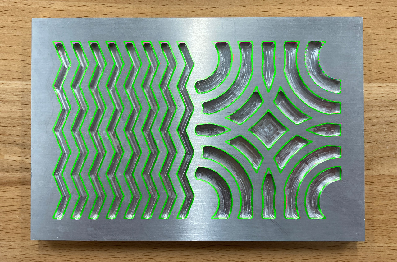
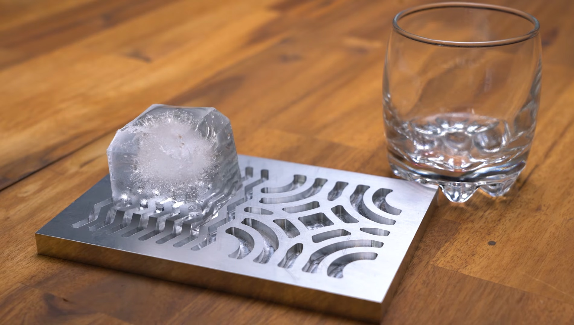
While your machine is cutting away, you might look closely as it reaches the detailed, curvy parts of the design and notice something: the final cut is a slightly different shape compared to our original 2D vector file. We actually chose this specific design to demonstrate a fundamental rule of CNC milling: you cannot cut a perfectly sharp internal corner with a round milling bit. If you look closely at the image on the right, you should be able to see the differences in these sharp corners. If you right-click on the image, you can open it in a new tab to really zoom in.
Because our bit is cylindrical, it will always leave a small radius in the corners of any pocket. You could use a much smaller milling bit to get tighter, sharper corners, but swapping to a tiny bit would drastically increase your total cutting time. For our ice tray, it isn't a big deal at all as we were expecting them to be a part of the design.
However, let's say your next project involves cutting a perfectly square hole to fit a matching square peg through it; you would run right into this exact issue, and your peg wouldn't fit! To fix this in the CNC world, you have to use a specific design workaround called a dogbone (where you intentionally overcut the corners). We aren’t going to dive into designing dogbones in this guide, but it is an essential concept worth remembering as you start designing your own functional, interlocking parts!
Fast forward about two hours, and the machine will spin down. The job is finished! Go ahead and carefully undo those clamps. Congratulations, that is your very first proper metal piece cut from start to finish!
Now, a quick but important note before you start serving drinks: this tray will not be food-safe straight off the mill. It requires a bit of post-processing to clean up microscopic burrs, remove machining oils, and properly treat the metal. That process is a whole other can of worms that we won’t cover today, but it isn't terribly difficult. If you want to use this for actual beverages, a quick Google search on how to make milled aluminium food-safe will point you to exactly what you need to do.
ONCE YOU HAVE PROCESSED IT TO BE FOOD SAFE, grab some large, clear ice cubes and let them sit on the metal tray for a bit. The thermal mass of the aluminium will rapidly melt the ice, imprinting your design perfectly into the bottom of the cube in seconds!
Where to From Here
Now, that was a nice and simple project to get our toes wet in the CNC milling process! This was purposefully designed to be an easy first win. We used a straightforward pocket cut with a simple 2D model, which allowed us to avoid a lot of the deeper complexities hidden within MakeraCAM. For instance, we didn’t have to worry about adding holding tabs to our stock, or coordinating multiple different cuts and tool changes on the same part.
There is still a bit more to learn as you progress on your CNC journey. To help with that, we have part 2 of this guide, where we will tackle 3D cutting! We will walk through how to mill a detailed 3D topographical map into a material of your choice, so definitely keep an eye out for that.
If you are reading through this and realise you still need to actually unpack and set up your Carvera, don't worry! We have a comprehensive Machine Setup Guide available, as well as a full Carvera Overview Guide to help you get completely acquainted with all of the machine's hardware and features before you make your first cut.
Finally, if you need a hand with anything we covered in this guide, or you made a funky custom ice tray and just want to show it off, feel free to head on over to our Community Forums (the topic for this guide is at the bottom of this page). We are all makers over there and are always happy to help!
Until next time, happy making!

