In this guide we will be taking a practical look at Voltage dividers - one of the most fundamental circuits in the world of electronics and this guide will hopefully be the only guide a maker ever needs to read. We will be taking a look at both the mathematical way to find your needed resistor values, and a math-free way through a free online simulation, as well as some rules on choosing resistors, how to wire up a circuit and how to use a divider conjunction with a microcontroller.
Let's get into it!
Contents:
What is a Voltage Divider?
A voltage divider can be thought of as a voltage "scaler". We choose certain resistor values to give the voltage divider a scaling factor. The voltage divider then takes in a voltage, and then uses that scaling factor to output a lower voltage - and it only scales down, not up!
This has a huge amount of application in the world of electronics and is a fundamental circuit, but the most relevant application for us makers is using them with microcontrollers and development boards to increase the voltage range they can read. Most microcontrollers can only ready a voltage up to 3.3 or 5 Volts and a voltage divider can be used to scale down a higher voltage into the range that our microcontroller can read. This 1guide is centred largely around doing this exact thing with a Raspberry Pi Pico, but it will be general enough to work with any microcontroller and even applications that don't involve microcontrollers.
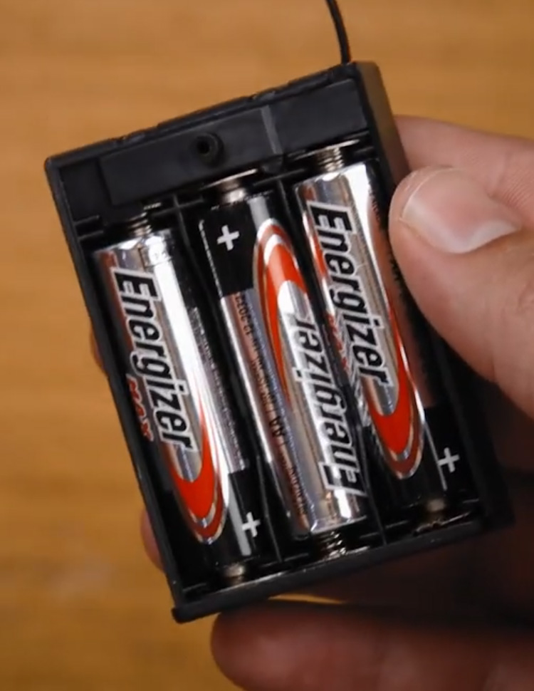
A very common application of a voltage divider and microcontroller combination (and one you should aim to do every chance you get), is a battery monitoring system. If your project is AA- or Lipo-powered, you can use a voltage divider to scale down the Voltage of that battery pack so that your microcontroller can effectively monitor how charged your batteries are - an incredibly helpful and often important ability in preventing batteries from over-discharging or going flat.
An important thing before we begin, the voltage dividers we will be building are not suitable for powering devices like servos, motors or even lights. We will take a look at what happens later but these are largely designed for reading voltage levels, signals and sensors. If you are going to try and use more than 5 or 10 milliAmps from the Voltage divider, you may start to run into some issues.
If you need to lower a voltage to power components like servos and motors, take a look at some of these step-down voltage regulators which are designed for this exact task and can handle more power.
If you are also looking to use a voltage divider to turn 5 Volt logic into 3.3 Volt logic, this need is common enough that you can find inexpensive bi-directional modules that are far easier to use than a Voltage divider.
Layout and Resistor Calculations
This section is going to get a bit technical with diagrams and equations, but don't worry as we will try to keep it all light and as approachable as possible.
Let's work with an example. We have a 3-cell LiPo battery and want to use a divider to monitor its Voltage level with a Pico. This is important because if the voltage drops below 9 Volts we will damage the battery, so we want to know when to shut down our project to prevent this. The maximum fully charged Voltage that we want to read is 12.6 Volts. So we will be designing a Voltage divider to scale 12.6 Volts down to 3.3 volts for our Pico to read it. You can follow along with the same steps to work with any other needed Voltages though.
First things first, what does our divider look like? I pulled this drawing from the video guide as it shows our key elements. We have the LiPo on the left outputting our 12.6 Volts. Two resistors are then connected in series from the positive to the negative terminal of the battery forming a closed electrical loop. Between these two resistors is where the output voltage will be. This is where we will connect the analog pin of our Pico to, and we will measure the voltage on here which hopefully should be between 0 and 3.3 Volts. We will also name our resistors R1 and R2. Finally a very important step, we will ensure that a ground pin of the Pico is connected to the negative terminal of the battery. This is because the Pico will use ground as a reference voltage - ground will be what it reads as 0 Volts and without this it won't be able to accurately read the battery.

Now let's look at the voltage divider equation. If you're not confident with math, that's completely okay as we will also look at a math-free way of doing this step. But don't skip straight to it as the equation is really simple and shows us a lot about how the divider works.
This is the equation below and it can be broken down into 3 parts. The output voltage (which is labelled as Vout on our diagram), is equal to the input voltage (our lipo battery) multiplied by the scaling factor that R1 and R2 make. And this is the key idea of the Voltage divider. There is a ratio between R1 and R2 that creates the scaling factor and all we need to do is appropriately choose R1 and R2 to get our desired scaling factor.

We can then go through and fill out the equation with our input voltage of 12.6 volts, our desired output voltage of 3.3 volts, and then an initial value or "guess" for R2. In this example, we decided to choose R2 as 1,000 ohms. After solving the equation, we found that a 2,818 ohm resistor would give us our desired output voltage of 3.3 Volts.
Now that we have R1 and R2, we can start building our divider right? Well, there are a few important things to consider first.

Rules for Choosing Resistor Sizes
There are two very important things to consider when choosing a resistor for your Voltage divider.
The first is to ensure that your resistor is sufficiently large enough. We will look at it later, but if the chosen resistor is too small, it will draw an excessive amount of current. Best-case scenario this will waste power, and worst-case scenario the excessive current will cause the resistor to catch on fire. The golden rule of thumb is to ensure that your resistors are between 1,000 and 10,000 ohms. But if you need to go outside of this range, don't be afraid to go on the higher side - 20,000 to 30,000 ohms is still just fine.
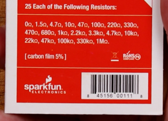
The second consideration is to ensure that it is possible to find the resistor size you calculated. Above we found that we need a 2818 ohm resistor, but you would be hard-pressed to find an exact resistor of this size. Resistors come in standard sizes, and in the image on the right you can see the standard sizes that come in my trusty resistor pack. There is a 1,000-ohm resistor, but the closest we have to 2,818 ohm is a 3,300-ohm resistor. So when choosing resistors for a voltage divider, ensure that you can source a resistor in that size, and you will nearly always need to choose the closest standard-sized resistor.
Voltage Divider Simulation
The Falstad Circuit Simulator is one of the best tools that you can use for voltage dividers. It not only provides you with a virtual simulation of how your circuit will behave but also allows you to rapidly try out different resistor combinations to find the one suitable for your divider.
By default, it will open to a complex circuit, but it has a pre-built Voltage divider we can open by heading to Circuits > Basics > Voltage Divider.

This will open up a circuit with two Voltage dividers. Click and drag to select all the components on the voltage divider on the right, and hit delete to remove them. If you are interested, you can come back to see how this multi-output divider works.
You should now be left with something that closely resembles the diagram we drew before.
You will also see that the wires are green in certain areas. This green is the voltage of the circuit, and it fades from green being a positive voltage, back to black being 0 volts or ground. There is also a series of yellow dots, and this represents the flow of current in our circuit.

Double-click on the voltage source (the 2 lines on the left) and you can change your input voltage. For our example, we are setting it to 12.6 Volts. Between the 2 resistors will be a meter showing the output Voltage of the divider This will be where our Pico plugs in, but for now, we will just read the output voltage with the meter. If you want to see the voltage of the battery, you can right-click and duplicate this meter, then drag the copy of it to the top node which will display your current output voltage.
Now you can double-click on each of the resistors to set your resistor sizes. We will fill out the values of 1,000 and 2,818 ohms (or 1k ohms and 2.818k ohms).

After entering our resistor values, you can see that our math was right and our 12.6v input is being scaled down to 3.3v, which our Pico can read.
There is an issue that we discussed earlier though and that is that we can't buy a 2818 ohm resistor. But thanks to this simulation, we can substitute it for the closest standard-sized resistor of 3,300 and see that our output Voltage becomes 2.93 Volts. While this isn't our ideal 3.3 volts, it is good enough for our situation as it is still in our Pico's 0 to 3.3 Volt readable range.
If you want to avoid using math and the Voltage divider equation to find your needed resistor values, this is your chance to do so. Play around and insert different standard-sized resistors to find a combination that gets you close to your target output voltage.

A helpful tip to remember is that you can pair resistors in series to add their values together. In the image on the right, 2.2k and 680 ohm standard-sized resistors are in series. These add to 2800 Ohms which brings us extremely close to our calculated resistor. This may be a better solution depending on your needs but for our purpose, we can work without it.

A quick side note, we can also experiment in Falstad to see why we need to choose sufficiently large enough resistors. In the image on the right, I am using 33 and 10 ohm resistors instead of 3.3k and 1k. These 2 resistor combinations give the exact same output voltage, but if we hover over the 33-ohm resistor, we can see that it is consuming 2.8 Watts of power.
These resistors are only suited to 1/4 of a watt and this amount of power would most likely cause it to instantly overheat and become a light bulb for a few seconds before burning out in a cloud of smoke. While we did pick a comically low resistor value for this to happen, picking resistors below the recommended 1k ohm minimum can consume excessive amounts of power. You can check this in Falstad by hovering over the resistor to see its information in the bottom right.

Another quick side note, we can also use Falstad to see why we can't power things like motors, servos and lights. In the image on the right, I have gone ahead and connected a 5 Volt motor to the output of our voltage divider. Without the motor our voltage output is 2.93 Volts, but the load that the motor puts on our circuit drops it to 0.114 Volts.
There is a bit of math to explore why this is the case and its outside the scope of this guide, but long story short, the motor is in parallel with the 1k resistor and this changes its effective resistance. This change in resistance changes our divider's output voltage. Ontop of this, the motor's resistance (technically called impedance) will rapidly change during its operation so we can't simply design the divider to account for this.

Wiring up a Voltage Divider
Now that we know what resistors we need (and we know that we can actually source them) let's wire up a circuit! Resistors aren't labelled with numbers, but instead use the coloured bands on them to represent their values. You can check out how to read them with this helpful tool.
Important: As always with wiring up circuits, ensure that it is not powered when placing components and always double-check that your connections are correct before turning on a circuit. Incorrect wiring can damage components on your circuit.
 Place the Pico into the breadboard. Ensure the micro USB connector faces outwards and that it is fully pressed into the breadboard so it sits flat and there are no gaps.
 Now we will connect our divider's input voltage. Here I connect 2 wires to the board that will plug into the battery. The negative black wire will be connected to the ground rail of the breadboard.
 Let's place our resistors. Place R1 and R2 in series like so, and ensure that it is connected to the ground/ the negative of the battery.
  Finally, we can connect our Pico to the divider. Connect any of the Pico's ground pins to the ground rail. This will ensure that our Pico, battery and divider all share a common ground.
 If you have a multimeter on hand, we can now test if the Voltage divider is working. In the image on the right, I have 2 meters. The one on the left is plugged directly into the battery and is reading that it's outputting its maximum voltage of 12.6 Volts. The meter on the left is measuring the output of our Voltage divider.
In Falstad we calculated the output voltage to be 2.93 Volts, but our circuit is slightly off. This realistically won't make much of a difference and you should expect there to be differences when you bring a virtual system into the real world. For example, the resistors are not EXACTLY 1,000 and 3,300 ohms, but instead measure to be 990 and 2,970 ohms.
You may need to unplug your microcontroller to accurately measure the output of the divider. It's not very visible here but the green wire was unplugged from the Pico. When it is plugged into the Pico, the resistances from it were instead giving an output of 2.2 Volts.

Reading With a Microcontroller
Let's get into the last step of reading our battery voltage by getting the Pico to read the output of the divider and calculate the voltage. We will be using Thonny and MicroPython, and if you need a hand or a refresher in these, you can check out our getting started guide. Plug your Pico into the computer, create a new script, and paste in the following code:
from machine import ADC
from time import sleep

# Initialize ADC on pin GP26 (ADC0)
adc = ADC(0)

# Input the values of R1 and R2
r1 = 3300
r2 = 1000

while True:
    raw_value = adc.read_u16()
    # Convert the raw digital reading of the ADC pin to the it's actual voltage (0 to 3.3 volts)
    voltage_out = (raw_value / 65535.0) * 3.3

    # Calculate input voltage based on voltage divider rule
    # Vout = Vin * (R2 / (R1 + R2)), thus Vin = Vout * ((R1 + R2) / R2)
    vin = voltage_out * ((r1 + r2) / r2)

    print("Input Voltage: {:.2f} V".format(vin))
    sleep(0.1)  # Read every 0.1 seconds
This code simply reads the voltage on Pin 26 of the Pico and uses the Voltage divider equation and values of R1 and R2 to work out what the input voltage is. Hit the green run arrow and it should be printing in the shell a value that is close to your input voltage.
On the right is an image of our results and as you can see we are getting pretty close to the actual voltage of the battery - within 0.2 Volts. We could improve this by accurately measuring the resistance of our resistors and using these values as we are just using 3.3k and 1k ohms. We could also calibrate this by altering the code to multiply the result by a number around 1.01 to give us a closer reading.

Conclusion
We now have a Pico that can read the approximate voltage of a battery thanks to a Voltage divider. Even if you are not using it for this exact application, you are now able to find a set of resistors to scale an input voltage down to a lower output voltage, and that is a really helpful tool to have in your maker toolbox. Whether you are using this to read a higher-voltage sensor, or you are monitoring a voltage level, we hope that this guide equips you with all the practical knowledge you need.
If you've found anything confusing or just have some questions, feel free to post in the conversation below - we're full-time makers and here to help!
Until next time, happy making!

