 Thanks to huge advancements in technology over the last decade, the maker community that we know and love has thrived. It’s now easier than ever before to get started with programming and tinkering due to the innovation from brands such as Arduino, Raspberry Pi, Sparkfun, Adafruit, and Teensy, just to name a few. You can buy an Arduino Uno for less than $40, plug it straight into your computer, and get coding right away. But sometimes it’s not that easy and we can take for granted the USB ports built into devices like these. Sometimes we need to be able to program a chip from our computer that doesn’t have a built-in USB port. For example, the Atmega328 that’s on the Arduino Uno doesn’t have a built-in USB port. Instead, there is a second, smaller chip on the board (Atmega16u2) which does have a USB port, then sends the data to the Atmega328. The Arduino Pro Mini is basically an Uno, without the Atmega16u2, and a much smaller form factor. In fact, you can take the 328 chip out of an Uno board, put it on a breadboard and with a 16 Mhz Crystal and two 22pF capacitors, you have a functioning Arduino, without the rest of the headers and jacks on the board.
So how do we go about programming something like this if we can’t connect it to our computer using USB? We use what’s called a USB-Serial converter.
Serial?
When we use the term ‘serial’ for these converters we are referring to TTL serial data compatible with the UART ports found on almost every chip (the Atmega328 has one UART port, the mega2560 has four). Before we go on, perhaps a term clarification is in order:
- Serial: When used in the context of digital communication, the word serial refers to the transmission of data in consecutive bits that are transmitted/received in sequence (one at a time).
- TTL: Transistor-Transistor-Logic is a method of using bipolar transistors to maintain and read digital signals. It refers to logic levels where a particular voltage (typically 3.3V or 5V) is the HIGH voltage, and 0V is the LOW voltage.
- UART: Universal Asynchronous Receiver/Transmitter is a digital hardware device which allows for a range serial data formats and configurable speeds (transmission speed is known as the baud rate).
- USB: Universal Serial Bus is now the default port for communicating to and from computer devices.
So as you can see, just because a computer has a USB port, doesn’t mean that you can just take the data lines and tack them onto a UART port, proper conversion must take place between the USB data protocol, and UART protocols. Some microcontroller chips, such as the Atmega16u2 have a built-in USB port (denoted by the ‘u’) which means that they have the hardware required to support USB communication built into them. However, the ones that don’t will usually have a UART port which we can use to program the board (providing the bootloader allows for this). The UART port on a board can be located by the pins labeled TX and RX. The TX pin is the transmit pin used to send data from the device to another device and the RX pin is the receive pin used to receive data from another device.
Fortunately, there exist plenty of devices designed to bridge this barrier: USB-Serial converters. They do exactly as the name implies, connect to the USB port of your computer, and convert the USB data into data compatible with a UART port which allows you to communicate to and from your device, to your computer. Chips also contain what is known as a ‘bootloader’ and this is just a small piece of code which tells your device what to do when it boots up. Now most chips on Arduino boards have a special bootloader on board which allows them to be programmed via the TX and RX pins, so we can also program our Arduino board using a USB-Serial converter. Sometimes these converters are also known as USB-TTL converters or USB FTDI converters. FTDI is a company who produces the most well-known USB-Serial converter chips and hence many converters are known simply as FTDI cables or converters.
Our Favourite Converters
With so many different options to choose from, we’ve selected a couple of our favorites to suit every project:
- USB to TTL Serial Cable: This is a basic FTDI USB-Serial converter with the convenience of the circuitry being built into the cable which means you can connect the female header leads directly up to your chip without needing a breadboard or soldering headers to another breakout board. This is the most basic, convenient option if you just want a simple USB-Serial converter with the TX/RX/5V/Gnd pins available. To use this cable, you will need to install the FTDI drivers as shown further down.
- Sparkfun USB to Serial Breakout FT232RL: This is the most versatile FTDI board on this list as it provides added features such as RX/TX LEDs to show bus activity, 3.3V, and 5V access, along with more advanced pin functionality of the FT232 chip (which aren't needed for this tutorial but can be useful for other serial applications). It is just as easy to use as the cable above but as a standalone board. To use this cable, you will need to install the FTDI drivers as shown further down.
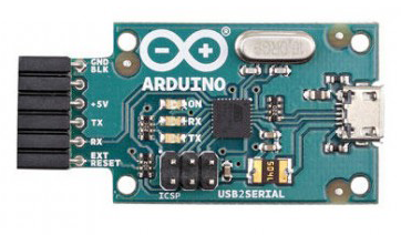
- Arduino USB 2 Serial Micro: This is the official Arduino brand USB-Serial converter and rather than being based on an FTDI chip, it uses an Atmega16u2 for the conversion, which is the same chip/circuit as found on the Uno, so you don't need to install the FTDI drivers and mentioned further down. The biggest advantage of this board is that it's programmed to use an extra pin which connects to the external reset pin on your Arduino to avoid having to manually use the reset button/pin. For info on connecting it up, check out the Arduino guide here.
Connecting It Up
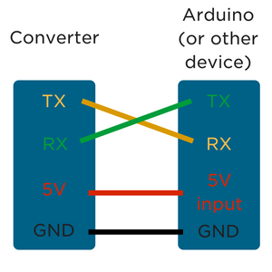
Connecting up the USB-Serial converter is pretty straight forward. You'll want to connect the 5V pin to the 5V input of your board to power it (or you can power it separately and only connect the ground). Then the TX pin on your converter to the RX pin on your board, and the RX pin on your converter to the TX pin on your board. If this sounds a bit confusing and backward, remember that TX is outgoing data, and RX is inbound data, so the TX pin on the converter is sending data from the USB port, and the RX pin on the Arduino is receiving data, so you want those to be connected, and vice-versa. If you're using the Arduino USB 2 Serial converter, you can take advantage of the external reset pin, check out the link above for wiring info.
Installing FTDI Drivers
![]() We’re going to run through using any of the boards above to program and communicate using the UART port on an Arduino, however, the method is going to be the same for any board with a UART port or has a bootloader capable of being programmed via the UART port. But first, we need to install the FTDI drivers which allow the converter board (with the FTDI chip on board) to show up as COM port. To download the drivers and get them setup, check out Sparkfun’s fantastic guide on setting installing FTDI drivers.
We’re going to run through using any of the boards above to program and communicate using the UART port on an Arduino, however, the method is going to be the same for any board with a UART port or has a bootloader capable of being programmed via the UART port. But first, we need to install the FTDI drivers which allow the converter board (with the FTDI chip on board) to show up as COM port. To download the drivers and get them setup, check out Sparkfun’s fantastic guide on setting installing FTDI drivers.
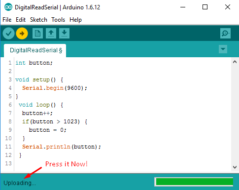
Now let’s take a look at sending data to our serial monitor using the converter. Open up Arduino IDE and copy the following code into it:
int button;

void setup() {
  Serial.begin(9600);
}
 void loop() {
  button++;
  if(button > 1023) {
    button = 0;
  }
  Serial.println(button);
 }
This is a super simple program that increments a variable by one, then prints the value of that variable to the serial monitor. The communication from our board to the computer is happening via the TX/RX lines to our USB-Serial converter so we can tell if it’s working or not. Now after installing the FTDI drivers, you should see your converter come up as a COM port. Target it, and ensure that you have the correct board type selected. Now something to take note of here is that the reset pin is required to program the Arduino board. In order for the Atmega328 to be programmed via the UART port, the reset pin must be held low and then released to high at a certain point during the upload process. The Arduino brand USB-Serial converter has a specific pin for this which you can connect to the reset pin, however, for the other boards, you will need to hold the reset button by hand. Here’s the correct sequence:
- Press and hold onboard reset button (or tie the reset header pin to low)
- Click the upload button to compile and upload to the board
- As soon as the progress bar changes from ‘compiling’ to ‘uploading’ release the reset button/pin
Success! Your board should now be successfully programmed using the USB-Serial converter! You can now leave it connected as is to allow serial communication between your board and the computer, and if you open up the serial monitor, you can see the count variable incrementing.
And that ladies and gentlemen is how you can use an FTDI board, otherwise known as a USB-Serial converter to program and communicate via the UART port on your board. Remember that not all chips can be programmed via UART (the Arduino bootloader makes this possible) but all chips can communicate via UART, for example, you could use a USB-Serial converter to allow a Raspberry Pi to communicate data to your computer using its serial port.

