Ultimaker 3D Printer Build Platform Calibration

Updated 01 February 2021

For Ultimaker 3D printers it is crucial to have a flat and level build platform which is parallel to the path of the nozzle. By having a correctly set up print space it will ensure the best possible results for all 3D printed components. As all Ultimaker 3D printers have a very similar method to manually level the base platform so I have formed this guide. Quick links for the contents of this guide is seen below.

It is important to level the build platform each time you change nozzle size, change out the glass build plate, alter any setting inside the build area, move the 3D printer to a new location or see issues with the first layer such as those explored in the troubleshooting example section.

If you've got any questions, queries or things to add to this topic please let us know your thoughts!


Manual Build Platform Calibration
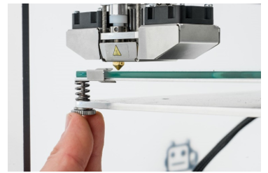
A delicate touchAll Ultimaker 3D printers on initial start-up run a manual build platform calibration wizard. This wizard will be displayed after you are greeted by the Ultimaker logo on boot and can also be re-run in the Maintenance option on the default menu screen (in the Build Plate submenu). The final goal of this process is to have a level build platform which is parallel to the path of the nozzle. The wizard will require manual adjustment of the three Z-axis screws found underneath the build platform. As a plane is uniquely determined by three non-collinear points this arrangement makes for an excellent system to get the best final build platform angle on your Ultimaker 3D printer.

1. The first step once the wizard is running is to wait for the Ultimaker 3D printer to do its homing procedure (the print head will move along its X-axis and Y-axis to learn its coordinate system). Keep your hands away from the build space when this is happening. Once the print head is in orientated at the centre and at the back of the build area it will stop movement and wait for user input.

See you in Cali2. If you're adjusting an Ultimaker 2+ 3D Printer, an Ultimaker 2 Extended+ 3D Printer or an Ultimaker 3 3D Printer the wizard will connect the build platform Z-axis movement to the LED-backlit control wheel. This will allow you to control the height of the build platform by rotating the control wheel. The Ultimaker S3 3D Printer and Ultimaker S5 3D Printer will have height control of build platform through the touchscreen display. Rotate the control wheel or use the touchscreen display to bring the build platform up to the print head nozzle tip leaving approximately a 1mm gap (make sure the distance between the two is close but don’t make contact between the build platform and the print head nozzle tip).  

3. Now press the next step on the wizard using the control wheel or touch screen display. The print head will then move to a front corner. Adjust the build platform height using the knurled nut currently directly underneath the print head to leave an approximate 1 mm gap (clockwise rotation to make the gap smaller). Pressing the next step in the wizard will move the print head to the other front corner. Adjust the build platform height using the other knurled nut directly underneath the print head to also leave an approximate 1 mm gap. Once completed and the next step is selected on the wizard the print head will move along the X-axis and the Y-axis checking the rough calibration and then stop at the centre and at the back of the build platform.

Caaaliiibration time cmon!4. If no problems occur the wizard will move onto the next phase. This process requires the calibration card that came in the accessories box and is done to fine-tune the build platform angle. Place the calibration in between the print head nozzle tip and the build platform. Now, while moving the calibration card back and forth, adjust the back knurled nut until you feel a slight resistance (be careful not to push on the build platform while fine-tuning as this will lead to inaccuracies, the pressure you put while rotating the adjustment nut will be enough to make this happen). If you cannot move the calibration card back and forth then the build platform is too close to the print head nozzle tip.

5. Once achieved, take the card and your hands out of the build area, press the next step on the wizard and the print head will move to a front corner. Now, while moving the calibration card back and forth, adjust the build platform height using the knurled nut currently directly underneath the print head. Once you feel that light resistance, take the card and your hands out of the build area and press the next step in the wizard. This will move the print head to the other front corner. Repeat this step for the third point.


Once achieved and having pressed the next step on the wizard the build platform calibration of your Ultimaker 3D Printer will be complete!


Active Build Platform Leveling
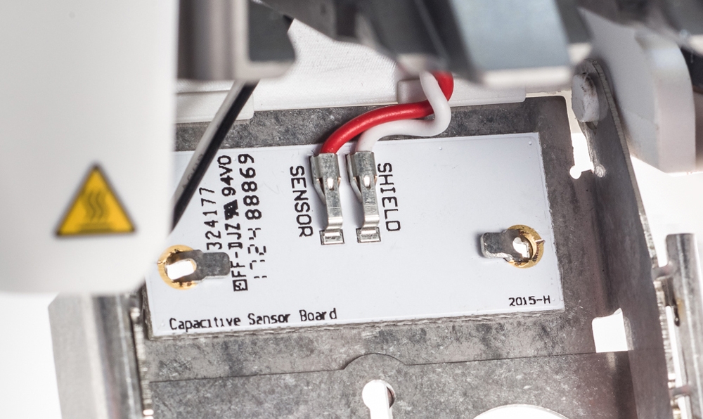

Cap-tivating Some Ultimaker 3D printers have active levelling technology. Active levelling is automatically performed by the 3D printer at the start of every print and is an excellent method to create reliable first layers. This is particularly useful if the build platform is not a perfect plane (which, naturally, it will never be as it is an object in the real world). This active levelling technology is achieved through a capacitive sensor inside the print head which detect tiny electric charge between the bottom of the print head and the aluminium plate of the print platform. The 3D printer will create a detailed heightmap of the build platform and this information is then used to compensate for any inaccuracies of the build surface during the first layers of the print by actively adjusting the build platform height.

Ultimaker products that have active build platform leveling capabilities are seen listed below.

The capacitive sensor is very sensitive so best practise when this process is occurring is; to not have any blobs of material on the end of the nozzle, have no external vibrations or electrostatic discharge affecting the 3D printer, ensure the fan cover is properly closed (as this is what the sensor is attached to) and to keep your hands safely out of the print area. By following this you will give the best chance to successfully producing your 3D printed components.


Examples for Troubleshooting 

When 3D printing a good first layer is one that is nicely pressed onto the glass plate with flat lines of filament and no gaps in between. Check out the below images to see a successful first layer and two unsuccessful ones. If your early prints are displaying imperfections like outside images take the time to re-level your build platform on your Ultimaker 3D printer. Settings inside your slicing software can also affect the first layer, check out our guide Printing Perfect First Layers - Ultimaker Cura for more information.

123

Have a question? Ask the Author of this guide today!

Please enter minimum 20 characters

Your comment will be posted (automatically) on our Support Forum which is publicly accessible. Don't enter private information, such as your phone number.

Expect a quick reply during business hours, many of us check-in over the weekend as well.

Feedback

Please continue if you would like to leave feedback for any of these topics:

  • Website features/issues
  • Content errors/improvements
  • Missing products/categories
  • Product assignments to categories
  • Search results relevance

For all other inquiries (orders status, stock levels, etc), please contact our support team for quick assistance.

Note: click continue and a draft email will be opened to edit. If you don't have an email client on your device, then send a message via the chat icon on the bottom left of our website.

Makers love reviews as much as you do, please follow this link to review the products you have purchased.