Welcome to the Meshtastic for Makers Workshop, a short course that teaches you everything you need to know about Meshtastic so you can go out and start wirelessly sending information in your projects with the Meshtastic network. This workshop is designed for complete beginners to Meshtastic and wireless communications. We will cover everything from hardware and software installation to writing code to send custom data, all through a series of concise bite-sized videos - we are trying to give you the best bang for your buck time-wise. However, this course is designed to require a small amount of experience with microcontrollers. If this is your first time picking up a microcontroller, you won't be completely left in the dark though and we have another entire Pico course to get you up to speed.
My Name is Jaryd, I'm an engineer and a passionate maker who loves to teach and produce educational videos, and I will be your instructor for this short course. This series also draws on the wisdom and insights from many of the folks here at Core Electronics who helped create this course.
To follow along you'll need an assortment of different bits and pieces which we will be looking at in each chapter. There is a limited selection of hardware that is Meshtastic compatible which is why much of this course will centre around using the Raspberry Pi Pico, and the Waveshare LoRa module for it. If you have a different microcontroller of choice, we have some options that can be explored later.
Each chapter contains a topic covered both in video and written form so pick whichever you are comfortable with. With that out of the way, let's get into it!
Course Outline:
- Chapter 1: What is Meshtastic?
- Chapter 2: Setting up the Pico
- Chapter 3: Channels and Frequencies
- Chapter 4: Sending Custom Sensor Data
- Chapter 5: Controlling Hardware via Meshtastic
- Chapter 6: Sending Meshtastic Data to MQTT
- Chapter 7: Sending Digital Sensor Data (Simple Method)
- Extra: Completely Resetting the Pico
1: What is Meshtastic?
First of all, we should explore what is Meshtastic and how it works as it is a little more advanced than traditional wireless communication methods.
Our usage for Meshtastic is a little different than usual. For most users, it's almost a 21st-century ham radio equivalent where you buy a small Meshtastic device, whack it in your pocket, and then through your phone you can talk to people that are in range via the device. In suburban areas, it is often used as a radio-based hobby, but it is also used in off-grid situations like hiking and camping trips where cellular connections are unreliable. Our use is going to be a little different though as we will be using the Meshtastic system to send and receive data in our projects.
Meshtastic uses the LoRa technology - a unique method of sending long-range radio signals with very little power consumption which makes it great for handheld and battery-powered devices. LoRa has seen a wide range of different applications, but it can be a bit of a challenge to send code from point A to point B, and depending on your setup, can require the use of some more expensive hardware. This is where things like Meshtastic come into play.
Meshtastic is a firmware that you can install onto a microcontroller to use LoRa a connected LoRa to easily send messages from point A to point B (we would call this peer-to-peer) and is best thought of as a text-based walky talky. But as the name suggests, it is also a meshing peer-to-peer network. If a Meshtastic device receives a message, it will repeat that message again. So if you want to send a message from point A to point B but point B is out of range, a device in the middle may be able to repeat the message and increase its range. Not only can this extend the range of a network, but it makes it easy to have lots of devices all talking together at once. Below is a diagram of how this repeating nature can overcome geographical obstacles.

But the true power of this comes from the fact that by default, any Meshtastic device will repeat any message. This includes other people, who's devices will act as repeaters for your messages and vice versa. Don't worry though, all of your messages can be encrypted - a device will repeat this encoded message word for word without knowing what it means, it will just be complete jibberish to it. So the more people using Meshtastic in your area, and the more Meshtastic devices around, the better the coverage of your network is. Even if you are only setting up 2 nodes to send sensor data from one place to another, you are also helping to build an off-grid network run by the people, for the people.
So what range can you expect with all of this? The performance of your Meshtastic device will depend on the performance of the LoRa module and antenna you are using. With the LoRa module and included antenna we will be using in this series, you can expect 3 to maybe even 5 kilometres with line of sight - where one device has direct vision to another. But the more things you place between 2 devices, the shorter the range. In an urban environment with lots of trees and houses in the way, you may only get 100 meters to 1 kilometre. Here in the suburbs of Newcastle we usually get between 100 to 300 meters. And like in the image above, any hills or mountains in the way will likely block a signal altogether.
So Meshtastic is a LoRa-based peer-to-peer network with meshing abilities. It is very dependant on having line of sight but can use multiple devices to repeat messages to improve coverage with more devices in the area resulting in a more comprehensive network for you and the community to use. And with that, you should know enough about how it works to start using it!
2: Setting up the Pico
The Meshtastic firmware can't just be flashed onto any old microcontroller it has a limited range of supported devices and the Pico is one of them. We have a lot of love for the Pico around here and the support for it, combined with the fact it is an inexpensive board makes it a good candidate for a Meshtastic device. If you were looking for a Meshtastic device to use as a purely communication device, there may be better options as the Pico has limited support for those uses. However, for our needs as a method of sending and receiving data in a maker project it fits well.
To follow along you will need a:
- Pico: At the time of writing only the original Pico and Pico W are supported and either can be used. However, we won't be using any of the wireless features of the Pico W so the original Pico is more than enough.
- Waveshare Lora Module: This module is based on the SX1262 LoRa chip and fits nicely on the Pico.
- Micro USB cable: This to just connect it to a computer to set it up.
There is also the option to plug in an SSD1306 OLED display. This is not essential an essential and we won't be using it, but it is a nice option to help see what is going on with the device as Meshtastic has some custom UI for it.
Let's assemble it!
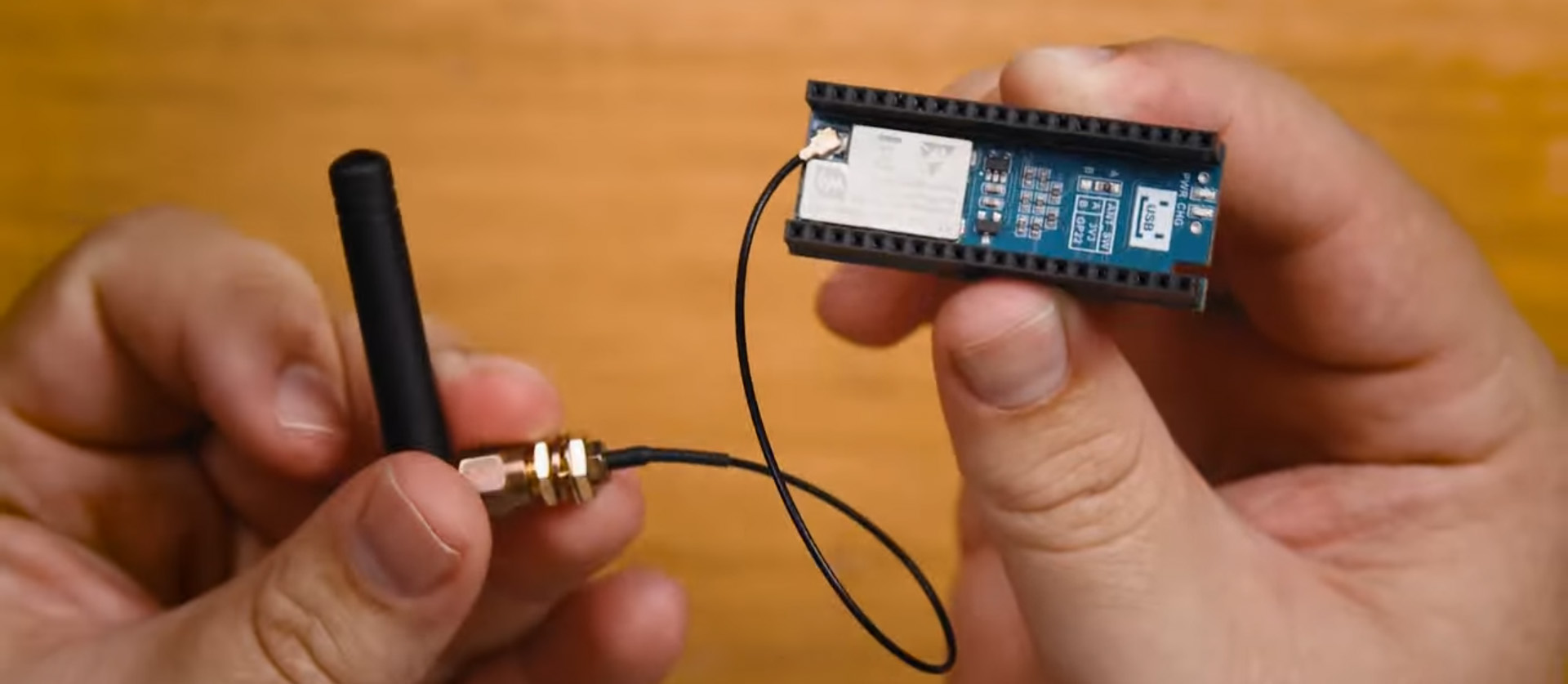 The LoRa module will come with an antenna and adapting cable, screw them together firmly and then attach them to the board.
 Then simply sit the Pico into the LoRa module. Ensure that it is placed in the correct orientation otherwise you may damage it. There is a marking on the module that shows the direction of the micro USB
 The LoRa module also may come with a small 600mAh battery. This can be connected to the board through the bottom battery connector, but this is entirely optional. The battery is quite small and can only power this setup for 12-24 hours.
 Again this is entirely optional but if you do wish to use the screen, you can do so by making the following connections:
Now we are ready to flash the Meshtastic firmware onto the Pico. Head on over to the web flasher and select your Pico model from the devices (there are different options for the original Pico and Pico W). Use what ever firmware version it defaults to in the 2nd option as this will ensure your device is running the latest stable version. Then hit flash which will allow you to download the needed UF2 file. With other devices the firmware can be flashed directly from this page, but for the Pico we will need to manually copy over the UF2 file.
Now press and hold the Pico's boot select button (the small white button near the USB port) and plug it into your computer. A new storage device should appear and you can let go of the button. Copy and paste that UF2 file we just downloaded into this storage device and the Pico will automatically restart and install the Meshtastic firmware in a few seconds.
Note: Only when we are flashing firmware do we need to hold the boot select button when plugging in the Pico. From now on you shouldn't need to.

Before we start using our device, we will first need to configure its operating region. Plug your Pico into your PC and open up the Meshtastic web client with a Chromium-based browser (Microsoft Edge and Google Chrome will both work). Add a new device and select serial. If your device isn't appearing here hit the "New Device" button and your browser will pop up with all the available COM ports. Select the one named "Pico".
Once your device is connected you will be greeted with the Meshtastic client in its full. From here you can configure your device and send messages over the network. To set the region select Config, then Lora and at the top, you will be able to select your region.
SELECTING THE RIGHT REGION IS EXTREMELY IMPORTANT. In every country is a specific set of frequencies that can be used for radio communications without the need for licenses or approval. These are the frequencies that Meshtastic uses and this setting ensures you are using them. If you select the wrong region, you will likely be breaking the law. We are in Australia so we will select our region of ANZ, but you should check which region you can use with this list.

Once you have selected the correct region, save it with the button in the top right. Your device will restart and start running in your region. Every time you save a setting like this and your device restarts, you will need to refresh the client webpage.
And with that, your Pico is up and running with Meshtastic! If you head on over to the Nodes tab, you should be able to see any other devices in range. Setting up a 2nd device can help check your setup is working - it can take a few minutes for a device to appear though. In the image on the right is the 2nd device we set up and because we are inside a warehouse, there are no other devices in range. But if you are in a populated area you may see someone.
Under the messages tab, you will have access to the public group chat. Messaging in here will send a message to anyone in range, say hello if you want! You can also select a device under Nodes and directly message it as well.

3: Channels and Frequencies
Don't skip over this one! Channels and frequencies are two extremely important settings you need to know before you start sending your valuable project data.
Open up the Meshtastic web client, connect your Pico and under Config > Lora, you will find the option to change a setting called frequency slot. Changing this value will change the radio frequency your device operates on. On the Meshtastic documentation site, you can find a tool that allows you to see what frequency slots are available in your region, and what frequency they utilise in Hz. With this we can see that in our Australian region slot 1 will make our device operate on 915.125 Mhz, and slot 2 will set it to 915.375 Mhz. While this 0.25 Mhz shift might not seem like much, it is enough of a shift to prevent them from communicating with each other - they probably won't even know about the other's existence. This is what changing frequency slots does - it isolates a device and ensures it doesn't repeat other device's messages. If all of your devices are on a different frequency slot, they will be operating on their own isolated frequency. The image below shows 2 devices working on a different frequency slot.

So what frequency slot do you select? By default your device will be set to slot 0. This isn't a usable slot but instead sets your device to the default slot of your region that every other device in your region will use by default. This default slot number changes from region to region, and here is a list of regions with their default slot number.
| Region | Frequency Slot | Region | Frequency Slot |
|---|---|---|---|
| US | 20 | CN | 36 |
| EU_433 | 4 | JP | 20 |
| EU_868 | 1 | ANZ | 20 |
| KR | 12 | TW | 16 |
| RU | 2 | IN | 4 |
| NZ_865 | 4 | TH | 16 |
| UA_433 | 6 | UA_868 | 2 |
| MY_433 | 4 | MY_919 | 16 |
| SG_923 | 4 | LORA_24 | 6 |
Because Meshtastic devices repeat messages they hear, if too many devices (about several hundred-ish) are in one area, a sort of "traffic jam" of messages can be created. And if you set up an array of devices, sending several messages a minute in a crowded city with a lot of other devices, you will be putting a great strain on this network and possibly causing these network "traffic jams". The responsible thing to do here would be to move your devices to a less busy frequency slot, something not on the default slot. If you only have 2 devices, and send only a few messages a day though - you may get away with staying on the default frequency.
If like most readers you live in an area with only a handle full to no devices, stay on the default frequency slot. There is already a lack of devices in your area and by staying on the default frequency slot you will be helping to build your local mesh's coverage.
Important: If you wish to stay on the default frequency, don't leave it on slot 0, and instead manually set the default slot number of your region. We will look at a case of it in a bit, but if you leave your frequency slot on 0, Meshtastic may move you from the default slot. Setting it manually will prevent this.
Let's talk about channels, and the best way to think of a channel is sort of like a group chat. Right now, regardless of what frequency slot our device is on, it will be sending messages in the public LongFast channel that every device in range is a part of. While this channel is great for a friendly conversation or meeting other users in your area, if we were to use it to send our sensor every minute, on the minute, we would very quickly annoy every other Meshtastic user in our area. To counter this you can create a private channel so only your devices can see messages from your devices. And best of all, even if you are on your own private channel, you will still be able to see all the other devices in your area, and contribute to the mesh network - they will repeat the messages of your private channel without knowing what it means. Below is a diagram of this in action.

To create a channel head to the Meshtastic client and open the Channels page. In the tabs at the top of the page are the 8 channel slots that you can set up. The first channel will be the primary channel which we must use. When we start sending sensor data, it will send it to whichever channel is set in this primary slot.
To create a channel, simply give it a name and optionally set a password for it. The password can be 8, 128 or 256-bit (or empty if you don't want a password), and will always end in two equal signs like in the image. The generate button on the side can also be used to generate a valid password. Scroll to the bottom, hit submit and your device is now in this channel! If you want to add another device to this channel, simply set it up with the same name and password, just be aware that it is case-sensitive.
Important! If you create a private channel AND you have left your frequency slot on 0, Meshtastic may try and move you away from the default frequency slot. This is in an attempt to help relieve network congestion. If you are using a private channel, ensure you have manually set your frequency slot to your region.

4: Sending Custom Sensor Data
Let's get into the real meat of this course - sending and receiving data from a microcontroller which is a bit more involved than you may think. The Pico is already running the Meshtastic firmware so it's not an easy task to simply write code on it to read a sensor and broadcast it. There are ways to natively plug in a sensor and send that data, but it requires specific sensors. Instead, we are going to go with the option that allows us to write our custom code, read any sensor we want, and have as much freedom as possible.
We are going to use a 2nd microcontroller to do all the sensor reading/data gathering, and then send that data via UART to the Meshtastic Pico which will be set up to broadcast that data to the network. For this 2nd microcontroller, we will be using another Pico, but you could use an ESP32, or an Arduino, or even use C++ - as long as you know how to send UART messages. But if you want to follow along with our code and wiring, you will need to grab yourself another Pico (and some jumper wires and breadboard to connect them).
 Start by placing the Picos into the breadboard. Place them as you wish, but we are crowding ours to one side so we can connect devices on the other side.
 Connect Pin 8 (TX) of one Pico to Pin 9 (RX) of the other Pico. Then make another connection from Pin 9 to Pin 8.
 We previously mentioned that you can connect an OLED screen to the Meshtastic Pico, we are going to use this as an opportunity to wire one up. This is entirely optional but may help with troubleshooting down the line.
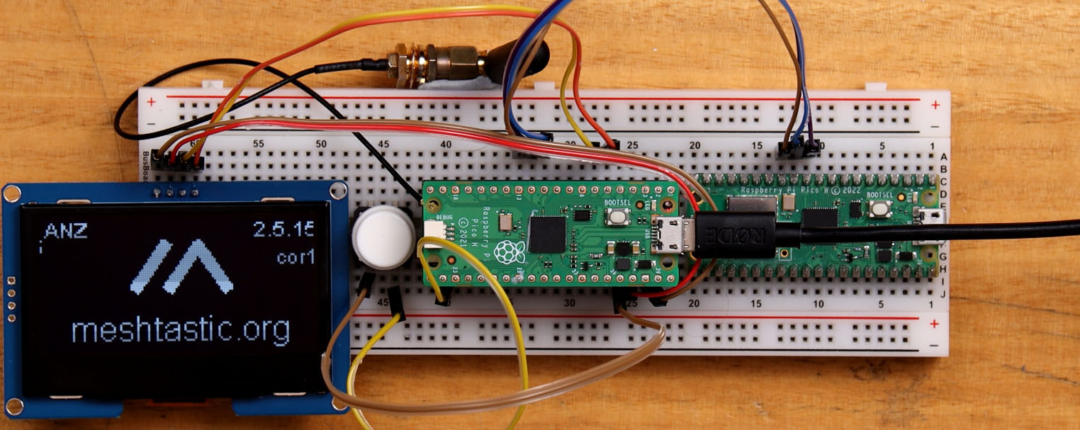 If you are adding a screen, there is also the option to add a button to navigate through menus. Again this is optional, but if you want to add one connect the following pins:
Plug your Meshtastic Pico into your computer and we will now configure its UART connection. Click on Config, and then you will see the Module Config tab appear below it. In this menu, we will want to find the Serial Module tab (serial is another term used interchangeably with UART). Start enabling the module, and setting the Receive Pin to 9 and the Transmit Pin to 8. Then go ahead and set the Baud Rate to 115,200. If your project calls for another baud rate then use it, but for this course, we will be using 115,200. And finally, we will set the Mode to Textmsg. This means that when a message is received over UART, the Pico will automatically send it to the Meshtastic network.
Now let's program our 2nd Pico! To do so we will be using our favourite IDE - Thonny. If you have never used Thonny with the Pico, or you need a refresher, you can follow our set-up video from the Pico Workshop. Connect your 2nd Pico, paste in the following code and hit run:
from machine import UART, Pin
import time

# Initialize UART 1, TX pin is GP8 and RX pin is GP9
uart = UART(1, baudrate=115200, tx=Pin(8), rx=Pin(9))

while True:
    uart.write('Test!')  # Send 'ON' message to the Meshtastic Pico
    time.sleep(5)      # Wait for 5 seconds
And you should see that your messages are being sent through every 5 seconds!

This code above is extremely stripped back and is just the bare minimum we need to send our data. The important takeaway is that we set up the UART connection, then anytime we call the following line, what ever text data we place in the brackets will be broadcasted to the Meshtastic network:
uart.write('The chicken coop door is open!!! ')
And with this, you can now read whatever sensors you want, run any calculations you want, and when you are ready, send information to your other Meshtastic Devices. Let's end this section with an example of this in action by reading this analog soil moisture sensor and sending the data every hour.
from machine import UART, Pin, ADC
import time

# Initialize UART 1, TX pin is GP8 and RX pin is GP9
uart = UART(1, baudrate=115200, tx=Pin(8), rx=Pin(9))

# Set up pin 26 (connected to our soil moisture sensor) as an analog input
soilSensor = ADC(Pin(26))

while True:
    reading = soilSensor.read_u16() # Take a sensor reading

    # Send the sensor reading. Note we have to turn it into a string first - UART can only send string variables.
    uart.write(str(reading))

    time.sleep(3600)      # Wait for 1 hour (60seconds * 60 minutes = 3600)
The most important thing in this demo is that we convert the reading to a string before we send it with UART. UART only accepts string type variables in MicroPython and our sensors typically read in either ints or floats. So before we can send that data we must convert it to a string first as shown in the UART writing line.
5: Controlling Hardware via Meshtastic
Now let's do the opposite and receive Meshtastic messages to control hardware plugged into our 2nd Pico. We can use the exact same hardware setup we used in the last chapter and we don't even need to change any settings in the Meshtastic client. The setup in the last video is not only able to send messages, but receive them - when the Meshtastic Pico receives a message, it will automatically repeat it over UART.
This section will largely be centred around unpacking that message into a useful format and managing the messaging system in our project. Let's start simple though and look at how we can receive these UART messages and control a servo. If you wish to follow along with this demo of controlling a servo, you will need to install the MicroPython servo library by heading to tools > manage packages and then searching for the library called "micropython-servo". You will also need to plug in a servo; power it with the 5v coming out of the Vbus pin, and plug the signal pin into GPIO 0 on the Pico. Now we can run the following code:
from machine import UART, Pin
from servo import Servo
import time

# Initialize UART 1, TX pin is GP8 and RX pin is GP9
uart = UART(1, baudrate=115200, tx=Pin(8), rx=Pin(9))

# Set up our servo plugged into pin 0
test_servo = Servo(pin_id=0)


# This function extracts the exact message sent from all the wrapping text around it
def process_uart_message(raw_message):
    """ Function to read from UART, process the message, and return the decoded message as a string. """
    # Locate the start of the message using the ": " delimiter
    colon_space_pos = raw_message.find(b": ")

    if colon_space_pos != -1:
        # Extract from the position after ': ' to before the last 2 chars (\r\n)
        extracted_message = raw_message[colon_space_pos + 2:-2]
        try:
            # Decode only the extracted part
            decoded_message = extracted_message.decode('utf-8')
            return decoded_message  # Return the extracted message as a decoded string
        except UnicodeDecodeError:
            error_message = ("Decoding error occurred with the extracted message.")
            return error_message
    else:
        error_message = ("Delimiter ': ' not found in the message.")
        return error_message
        return None


while True:
    # Check if anything is available in the UART buffer
    if uart.any():
        # Get the message from the buffer if there is
        message = uart.read()
        # Run the message through the function which will remove anythning unnessescary
        fixed_message = process_uart_message(message)

        # We will try to do this
        try:
            # Write the number received to the servo, note the use of int()
            # When a message is received over UART it is a string and we cant write it to the servo
            test_servo.write(int(fixed_message))
            print(fixed_message)

        # If there is an error with that we will do this instead (pass does nothing)
        except:
            pass
This code starts off as usual by importing all the libraries needed, and setting up our UART perhipheral (exactly like last chapter), as well as the servo we plugged in. Then it comes to this large function here:
def process_uart_message(raw_message):
    """ Function to read from UART, process the message, and return the decoded message as a string. """
    # Locate the start of the message using the ": " delimiter
    colon_space_pos = raw_message.find(b": ")

    if colon_space_pos != -1:
        # Extract from the position after ': ' to before the last 2 chars (\r\n)
        extracted_message = raw_message[colon_space_pos + 2:-2]
        try:
            # Decode only the extracted part
            decoded_message = extracted_message.decode('utf-8')
            return decoded_message  # Return the extracted message as a decoded string
        except UnicodeDecodeError:
            error_message = ("Decoding error occurred with the extracted message.")
            return error_message
    else:
        error_message = ("Delimiter ': ' not found in the message.")
        return error_message
        return None
You don't need to know how this function works (but it is a great learning opportunity), but knowing what it does is quite important. If we sent the message "Hello" over Meshtastic and received it via UART, that message would look something like the following:
b'\r\n\x88\x8e\x01 \x04: Hello\r\n'
As you can see our message is in there, but it is surrounded by a few encoding artifacts. If the message is sent to this function, it will remove all the unnecessary characters and just extract our message to give: Hello.
Then we enter into our forever-looping while true statement and start by checking if any message is held in the UART buffer. When the Pico receives a message via UART, it is held in this buffer until we read it. If there is something in there, we will store it in the variable called message, and then send it off to the function we looked at above to extract just the message part of it.
while True:
    # Check if anything is available in the UART buffer
    if uart.any():
        # Get the message from the buffer if there is
        message = uart.read()
        # Run the message through the function which will remove anything unnecessary
        fixed_message = process_uart_message(message)
Now with our message ready, we can finally set the servo to the angle in the message. And this is really easy if our message only contains a single number between 0 and 180 as this matches the 0 and 180 degrees of our servo. However, if we tried to set the angle with a message containing a number outside of this range, or even with a word like "Hello!", it would crash our program. As a result, it is important that we implement error handling into our code, and one of the best tools is with the try and except keywords.
Below is how we would implement them and the code tries to write the message to the servo, but if that gives an error it will do what is nested in the except section (and the pass keyword is just a way of doing nothing). Also note that we need to turn our message into an int with int() before we use it to set the angle of the servo.
        # We will try to do this
        try:
            # Write the number received to the servo, note the use of int()
            # When a message is received over UART it is a string and we cant write it to the servo
            test_servo.write(int(fixed_message))
            print(fixed_message)

        # If there is an error with that we will do this instead (pass does nothing)
        except:
            pass

With this, we can now send a message on our channel to control the angle of a servo. But this doesn't need to be just a servo and with a bit of modification, it could just as easily control the speed of a motor, the brightness of a light, a linear actuator or solenoid, or even the state of a relay to control some other circuit.
However, what if we had another device with a servo we wish to control as well? With this current code, both would receive the number and set their servos to the same angle which we might not want. To fix this we are going to need to create a messaging system. How you do this is up to you and should fit the needs of your project, but for this course, we are going to use a system of having a topic, followed by the value. If we wanted to send a message that the front gate is open our message might look like: front_gate:open. If we wanted to report a soil moisture reading for our 2nd plant it might look like: soil2:29620.
In this example, we are going to set up our Pico to search for a message like: servoA:45 and then set the angle of the servo the number after the colon. To do so we can replace the while true loop with the following one:
while True:
    # Check if anything is available in buffer
    if uart.any():

        # Get the extracted message
        message = uart.read()
        fixed_message = process_uart_message(message)

        # Check if message starts with servoA:
        if fixed_message.startswith('servoA:'):
            try:
                # Extract the number after servoA:
                angle = fixed_message.split(':')[1]
                test_servo.write(int(angle))

                print(f"Setting servo to {angle} degrees")

            except:
                print(f"Invalid servo message: {fixed_message}")

        else:
            print(f"Ignored message: {fixed_message}")
This is quite similar to our previous example, with the addition of the following important lines.
Our bread and butter of this is all is the following line that returns true if a message starts with a specific series of numbers or letters:
if fixed_message.startswith('servoA:'):
And then the following line splits the message at the colon and takes the value after it, which we can then write to the servo:
                angle = fixed_message.split(':')[1]
                test_servo.write(int(angle))
With this, we now have a device that listens for messages and if it starts with servoA: it will use the value after the colon to control a servo. If we alter the code and upload it to the other device so it looks for messages starting with servoB: we would now have a system where we can independently address a board and control each servo separately.
Let's end this chapter by looking at one more example of setting up a Pico to display information it receives on an OLED screen. Ensure that you have installed the OLED library we are using called "micropython-ssd1306-driver". There is quite a bit going on in this code and we go through its workings in the video for this chapter.
from machine import UART, Pin, SoftI2C
from ssd1306 import SSD1306_I2C
import time

# Initialize UART 1 on Pico B, TX pin is GP4 and RX pin is GP5
uart = UART(1, baudrate=115200, tx=Pin(8), rx=Pin(9))

# OLED Setup
screen_width = 128
screen_height = 64
i2c = SoftI2C(scl=Pin(5), sda=Pin(4))
oled = SSD1306_I2C(screen_width, screen_height, i2c)

# Dictionary to store last update times for each slot
last_updates = {}

def process_uart_message(raw_message):
    """ Function to read from UART, process the message, and return the decoded message as a string. """
    colon_space_pos = raw_message.find(b": ")

    if colon_space_pos != -1:
        extracted_message = raw_message[colon_space_pos + 2:-2]
        try:
            decoded_message = extracted_message.decode('utf-8')
            return decoded_message
        except UnicodeDecodeError:
            error_message = ("Decoding error occurred with the extracted message.")
            return error_message
    else:
        error_message = ("Delimiter ': ' not found in the message.")
        return error_message

def format_time_ago(seconds):
    """Format time ago in hours or minutes"""
    if seconds < 3600:  # Less than an hour
        minutes = seconds // 60
        return f"{minutes}m"
    else:
        hours = seconds // 3600
        return f"{hours}h"

def update_display_slot(slot_num, name, value):
    """Update a specific slot (1-6) with the sensor name, value, and time"""
    y_pos = (slot_num - 1) * 11

    # Clear the slot area
    oled.fill_rect(0, y_pos, screen_width, 11, 0)

    # Draw the name, value, and time
    oled.text(name, 0, y_pos)
    oled.text(value, 52, y_pos)

    # Calculate and display time ago if we have a timestamp for this slot
    if slot_num in last_updates:
        time_ago = time.time() - last_updates[slot_num]
        time_str = format_time_ago(time_ago)
        oled.text(time_str, 104, y_pos)

    # Draw horizontal line
    oled.hline(0, y_pos + 8, screen_width, 1)

    # Draw vertical lines
    oled.vline(50, 0, screen_height, 1)
    oled.vline(102, 0, screen_height, 1)

    oled.show()

def update_all_times():
    """Update all displayed times without changing values"""
    for slot_num in last_updates:
        y_pos = (slot_num - 1) * 11
        # Clear only the time area
        oled.fill_rect(104, y_pos, 24, 8, 0)
        # Update the time
        time_ago = time.time() - last_updates[slot_num]
        time_str = format_time_ago(time_ago)
        oled.text(time_str, 104, y_pos)
    oled.show()

# Initialize OLED
oled.poweron()

# Variables for timing the display updates
last_time_update = time.time()

while True:
    current_time = time.time()

    # Update times every minute
    if current_time - last_time_update >= 30:
        update_all_times()
        last_time_update = current_time

    # Check if anything is available in buffer
    if uart.any():
        # Get the extracted message
        message = uart.read()
        fixed_message = process_uart_message(message)

        # Check for different sensor messages
        if fixed_message.startswith('soil1:'):
            value = fixed_message.split(':')[1]
            last_updates[1] = current_time
            update_display_slot(1, "Soil1", value)

        elif fixed_message.startswith('soil2:'):
            value = fixed_message.split(':')[1]
            last_updates[2] = current_time
            update_display_slot(2, "Soil2", value)

        elif fixed_message.startswith('temp:'):
            value = fixed_message.split(':')[1]
            last_updates[3] = current_time
            update_display_slot(3, "Temp", value)

        elif fixed_message.startswith('humid:'):
            value = fixed_message.split(':')[1]
            last_updates[4] = current_time
            update_display_slot(4, "Humid", value)

        elif fixed_message.startswith('rain:'):
            value = fixed_message.split(':')[1]
            last_updates[5] = current_time
            update_display_slot(5, "Rain", value)

        elif fixed_message.startswith('front_gate:'):
            value = fixed_message.split(':')[1]
            last_updates[6] = current_time
            update_display_slot(6, "Gate", value)

        else:
            print(f"Ignored message: {fixed_message}")

    time.sleep(0.2)
And with these scripts you should have enough examples to go out and write your own code to "do something" with received Meshtastic messages. Although our examples have been for specific use cases, large language models like ChatGPT, Claude and Deep Seek will be able to help you re-write this code to fit your needs if you paste in any of these demo codes (this last one might be better though).
6: Sending Meshtastic Data to MQTT
At this point, we know how to send and receive data across a mesh network, and with this, we can create our own off-grid system. Let's now learn how to use MQTT to create an endpoint to connect our off-grid system to the internet.
We should clarify now that this is not the regular usage of MQTT that you may come across in the community. Usually, when someone mentions using MQTT with Meshtastic, they are often talking about network tunnelling meshes together. This is where you have one mesh, and use an MQTT to connect it to another mesh via the internet.
We are doing something else. We are creating a connection point to allow our off-grid system to interact with the internet or other network-based systems - all through an MQTT broker. If you connected this to the Adafruit IO broker, you would be able to monitor your network from anywhere in the world. If you connected it to a home assistant MQTT broker, you would be able to integrate it with your home assistant set-up. Whatever you want to do with it, if it is MQTT compatible, you will be able to connect it to your mesh network. In this section, we will be going through an example of connecting it to Adafruit IO, but the process will work with any other broker. Below is an image of what this setup might look like.

To connect our Meshtastic node to an MQTT broker we will be using the 2nd microcontroller which we previously connected via UART. Very importantly, that microcontroller needs to support Wi-Fi connectivity. For this example, we are using the Pico W, but if you wish to use another microcontroller it is definitely possible. If this is your first time using Adafruit IO or MQTT with a microcontroller, we have a stand-alone guide which much of this section was based on.
To begin, install the "micropython-umqtt.simple" library through thonny. This is a fantastic library that is going to simplify using MQTT. Also ensure that you have created an Adafruit IO account - its free with a limited amount of topics and data rate.

Then paste in the following code which is a modification of a previous script with the addition of MQTT interactions:
import network
import time
from math import sin
from machine import UART, Pin
from umqtt.simple import MQTTClient
import uasyncio as asyncio

# WiFi Configuration
wifi_ssid = ""
wifi_password = ""

# MQTT Configuration
mqtt_host = "io.adafruit.com"
mqtt_username = "Jaryd_Giesen"  # Your Adafruit IO username
mqtt_password = ""  # Adafruit IO Key
mqtt_client_id = "" # needs to be a UNIQUE name no one else has

mqtt_soil_topic = "Jaryd_Giesen/feeds/soil1"  # The MQTT topic for soil data
mqtt_temp_topic = ""  # The MQTT topic for temperature data
mqtt_receive_topic = "" # The MQTT topic for light control

# Initialize UART 1 on Pico
uart = UART(1, baudrate=115200, tx=Pin(8), rx=Pin(9))

# Set up onboard LED
led = Pin("LED", Pin.OUT)

def connect_wifi():
    """Connect to WiFi network"""
    wlan = network.WLAN(network.STA_IF)
    wlan.active(True)
    wlan.connect(wifi_ssid, wifi_password)
    while not wlan.isconnected():
        print('Waiting for connection...')
        time.sleep(1)
        led.toggle()
    print("Connected to WiFi")
    led.on()
    return wlan

def process_uart_message(raw_message):
    """Process UART message and return decoded string"""
    colon_space_pos = raw_message.find(b": ")

    if colon_space_pos != -1:
        extracted_message = raw_message[colon_space_pos + 2:-2]
        try:
            decoded_message = extracted_message.decode('utf-8')
            return decoded_message
        except UnicodeDecodeError:
            return "Decoding error occurred with the extracted message."
    else:
        return "Delimiter ': ' not found in the message."

def mqtt_subscription_callback(topic, message):
    """Handle incoming MQTT messages by forwarding them to UART"""
    print(f'Topic {topic} received message {message}')
    # Forward the message to UART
    uart.write(message + b'\r\n')

async def handle_uart():
    """Async task to handle UART messages and publish to MQTT"""
    while True:
        if uart.any():
            message = uart.read()
            fixed_message = process_uart_message(message)

            if fixed_message.startswith('soil1:'):
                try:
                    soil_value = fixed_message.split(':')[1]
                    print(f'Publishing soil reading: {soil_value}')
                    mqtt_client.publish(mqtt_soil_topic, soil_value)
                except Exception as e:
                    print(f'Failed to publish soil data: {e}')

            elif fixed_message.startswith('temp:'):
                try:
                    temp_value = fixed_message.split(':')[1]
                    print(f'Publishing temperature reading: {temp_value}')
                    mqtt_client.publish(mqtt_temp_topic, temp_value)
                except Exception as e:
                    print(f'Failed to publish temperature data: {e}')

            else:
                print(f"Ignored message: {fixed_message}")

        await asyncio.sleep(0.1)

async def handle_mqtt():
    """Async task to check for MQTT messages"""
    while True:
        try:
            mqtt_client.check_msg()  # Blocking check for messages
            await asyncio.sleep(0.1)  # Small delay to prevent tight loop
        except Exception as e:
            print(f'MQTT error: {e}')
            # Try to reconnect
            try:
                mqtt_client.disconnect()
                mqtt_client.connect()
                mqtt_client.subscribe(mqtt_receive_topic)
                print("Reconnected to MQTT broker")
            except:
                print("Failed to reconnect to MQTT broker")
            await asyncio.sleep(5)  # Longer delay before retry


# Connect to WiFi
wlan = connect_wifi()

# Initialize and connect MQTT client
mqtt_client = MQTTClient(
    client_id=mqtt_client_id,
    server=mqtt_host,
    user=mqtt_username,
    password=mqtt_password)

# Set up MQTT callback and connect
mqtt_client.set_callback(mqtt_subscription_callback)
mqtt_client.connect()
mqtt_client.subscribe(mqtt_receive_topic)
print("Connected and subscribed to MQTT broker")

try:
    # Create tasks for UART and MQTT handling
    uart_task = asyncio.create_task(handle_uart())
    mqtt_task = asyncio.create_task(handle_mqtt())

    # Run both tasks concurrently
    asyncio.run(asyncio.gather(uart_task, mqtt_task))

except Exception as e:
    print(f'An error occurred: {e}')
finally:
    mqtt_client.disconnect()
    print("Disconnected from MQTT broker")
This code will need a few details filled out, so lets go over what you will need to input, and also use it as an opportunity to see how it works. First of all, we declare a heap of important information, starting with the credentials of the Wi-Fi network it will be connecting to. Enter here the name and password of your network:
# WiFi Configuration
wifi_ssid = ""
wifi_password = ""
Then we will need to enter our MQTT details including the host name, your user name on that broker, the borker password/key and then a client ID. This client ID is simply a unique identifier you can give to this node, make it something that no one else is using.
# MQTT Configuration
mqtt_host = "io.adafruit.com"
mqtt_username = "Jaryd_Giesen"  # Your Adafruit IO username
mqtt_password = ""  # Adafruit IO Key
mqtt_client_id = "" # needs to be a UNIQUE name no one else has
Then we need to fill in the names of the feeds/topics that we want to be using. I have 3 examples in this code, the first two will be used to send data to our broker, and the third will be used to receive information. You should delete or create as needed to match the number of topics you are using. We have left the soil1 topic feed in as an example of how this needs to be formatted with "user_name/feeds/topic_name". Once you have all of this information entered into your code, be careful whenever you share so as to avoid sharing any important private information.
mqtt_soil_topic = "Jaryd_Giesen/feeds/soil1"  # The MQTT topic for soil data
mqtt_temp_topic = ""  # The MQTT topic for temperature data
mqtt_receive_topic = "" # The MQTT topic for light control
After this section is a series of functions - we will circle back to them when they are relevant. On to the main section of our code, the first thing that will be called is the connect_wifi() function. This connects your Pico to the Wi-Fi network with the details you provided. Connecting microcontrollers to Wi-Fi often results in errors, especially in the setting-up phase. If you encounter connectivity issues, unplug your device for a few seconds, and try again. Even if you stop the code and run it again the Wi-Fi module does not reset and needs to have a complete power-down to reset.
# Connect to WiFi
wlan = connect_wifi()
Then we use the MQTT library we installed to set up our connection the MQTT broker.
# Initialize and connect MQTT client
mqtt_client = MQTTClient(
    client_id=mqtt_client_id,
    server=mqtt_host,
    user=mqtt_username,
    password=mqtt_password)

# Set up MQTT callback and connect
mqtt_client.set_callback(mqtt_subscription_callback)
mqtt_client.connect()
mqtt_client.subscribe(mqtt_receive_topic)
And finally, we try to run some asyncio code. Asyncio is a really cool Python tool that allows you to run two or more pieces of code at the same time. It's like getting the Pico to multi-task.
try:
    # Create tasks for UART and MQTT handling
    uart_task = asyncio.create_task(handle_uart())
    mqtt_task = asyncio.create_task(handle_mqtt())

    # Run both tasks concurrently
    asyncio.run(asyncio.gather(uart_task, mqtt_task))

except Exception as e:
    print(f'An error occurred: {e}')
finally:
    mqtt_client.disconnect()
    print("Disconnected from MQTT broker")
The pieces of code we wish to run with asyncio have to be stored in an asyncio function. The first function should look extremely similar to what we have previously done. It constantly checks the UART connection for any incoming messages (from our Meshtastic network), and if it receives one, it runs it through process_uart_message() to extract the message part of it we want. Then it checks if it starts with our message formatting, and then sends the 2nd half of it after the colon to our MQTT broker.
async def handle_uart():
    """Async task to handle UART messages and publish to MQTT"""
    while True:
        if uart.any():
            message = uart.read()
            fixed_message = process_uart_message(message)

            if fixed_message.startswith('soil1:'):
                try:
                    soil_value = fixed_message.split(':')[1]
                    print(f'Publishing soil reading: {soil_value}')
                    mqtt_client.publish(mqtt_soil_topic, soil_value)
                except Exception as e:
                    print(f'Failed to publish soil data: {e}')

            elif fixed_message.startswith('temp:'):
                try:
                    temp_value = fixed_message.split(':')[1]
                    print(f'Publishing temperature reading: {temp_value}')
                    mqtt_client.publish(mqtt_temp_topic, temp_value)
                except Exception as e:
                    print(f'Failed to publish temperature data: {e}')

            else:
                print(f"Ignored message: {fixed_message}")

        await asyncio.sleep(0.1)
The other piece of code we will run at the same time simply checks our MQTT broker for any new messages that it might of sent. Much of this function is error handling in the event that the MQTT client gets disconnected:
async def handle_mqtt():
    """Async task to check for MQTT messages"""
    while True:
        try:
            mqtt_client.check_msg()  # Blocking check for messages
            await asyncio.sleep(0.1)  # Small delay to prevent tight loop
        except Exception as e:
            print(f'MQTT error: {e}')
            # Try to reconnect
            try:
                mqtt_client.disconnect()
                mqtt_client.connect()
                mqtt_client.subscribe(mqtt_receive_topic)
                print("Reconnected to MQTT broker")
            except:
                print("Failed to reconnect to MQTT broker")
            await asyncio.sleep(5)  # Longer delay before retry
And the final piece of all of this is the mqtt_subscription_callback() function. When a message is received from our broker, we execute the code in this function - in this example, all we are doing is writing that message over UART (which transmits that message to the Meshtastic network).
def mqtt_subscription_callback(topic, message):
    """Handle incoming MQTT messages by forwarding them to UART"""
    print(f'Topic {topic} received message {message}')
    # Forward the message to UART
    uart.write(message + b'\r\n')
Run this code and your 2nd Pico should connect to your Wi-Fi network, then your MQTT broker, and if you send a message over the network with the right messaging prefix we have been using, it will be sent to MQTT. Inversely, if you send data from the MQTT server on a topic that the Pico is subscribed to, it will be repeated to your network. This might be a helpful way to control a device too remote for the internet (but not Meshtastic), from the internet anywhere in the world. The video for this section has great footage of all of this in action.
7: Sending Digital Sensor Data (A Simpler Method)
Let's take a look at another method of sending data with a digital sensor - a sensor that outputs either an off or on signal, like a button. With this method we can only send this simpler type of sensor data, the trade-off is that we don't need the 2nd Pico as it will all be done through the detection sensor module in the Meshtastic client.
Although we are limited to this simple sensor type, there is still quite a lot we can "sense" with it. This could be a button or switch monitoring whether a gate or door is open, an infrared sensor looking for sunlight, a float switch monitoring the water level of a tank, or a motion-detecting PIR sensor which we will be setting up in this section.
But first, we will set up a simple button and explore the settings in the detection sensor module. Plug in your Meshtastic Pico, head on over to the Meshtastic client and look for the detection sensor module under the Module Config Menu.
You are greeted by a range of settings, first ensure that the module is enabled. Then you will see the two settings in the image on the left, and these are the main settings that determine the sending behaviour of your sensor.
Setting a number in the "minimum broadcast seconds" will set up your device to send a message when the button is pressed. The number you enter into this section is how rapidly the message can be sent. If it is set to three seconds, you would press the button, a message would be sent, and then it doesn't matter how often you press the button - only after 3 seconds have passed will a button press send a new message.

If you set the above setting to zero and specify a time in the "state broadcast seconds" setting, you will set it up to periodically send the state of that button every amount of seconds you specify. So if you set it to 60, the state of the button would be sent every minute - a measurement of whether it's pressed or not. For the rest of this section we will be using the first method, so set the time on this second method to zero to disable it.
After that, you will need to set a friendly name that affects the message that we will be sending. If it is set to "door:", then when the button is pressed it will send the message "door: detected". If we are using the second method of periodically sending the state of the button it will come through as "door: 0" or "door: 1". Just be aware that when this module sends a message it has a space after the colon, and previously in our messaging system we haven't been using spaces to simplify everything a little. If you write code to handle these messages, just keep in mind you will have to deal with them.
Under the "monitor pin" setting you will want to set 21 which is the GPIO pin we will plug our button into. You will also want to ensure that "detection triggered high" is off. This means that the pin will be triggered and considered pressed when it is connected to ground or LOW - which is how we will wire our button (we also call this active-low). And finally, we want to turn on "use pullup". This enables the internal pull-up resistor in the Pico so that when we press the button, the voltage lowers to ground, and when we release it, the pull-up resistor brings it back up to 3.3 volts or HIGH, almost like a spring. Be sure you save the settings.
To connect the button, wire one side of it to ground, and the other side of it to Pin 21 of the Pico. Once you have made this connection, plug in your Pico and watch it send your messages!

Now let's take a quick look at how we can use an active-high set-up with this module, the opposite of what we just configured. Why would we want to do this though? Well, most sensors use this active-high system - sensors like a PIR sensor which normally outputs 0 volts (or ground), and when motion is detected, it outputs 3.3 volts / a high signal.
Go ahead and plug your sensor into the Pico, our PIR sensor is plugged into the pins from the Pico providing power, and the signal pin is in Pin 21, exactly the same as our button.
In the Meshtastic client, the only things we will need to change are the "detection triggered high", which should be set on, and the "use pullup", which should be off. Unfortunately, Meshtastic doesn't currently support using pull-down resistors, however, our sensor modules typically won't need them, it's more of an issue for buttons. If you wish to use this active-high configuration with a button, you will need to wire your own pull-down resistor manually (or just use the active-low method from before).

Save those settings and give it a go. You should now be able to trigger your sensor and have a message sent as a result of it!
And with this, you are now able to send simple data from a digital sensor through the Meshtastic network, without the need for a second Pico or UART.

Extra: Completely Resetting the Pico
Have you changed a setting in your Meshtastic client and things aren't working anymore? You might have soft-bricked your Pico. Throughout this course, we have specified safe settings in the Meshtastic client that are compatible with the Pico. However, it is quite easy to incorrectly set something and soft-brick your Pico - especially when you are experimenting and mainly by setting incompatible Pin numbers. The Meshtastic firmware has a weird quirk where after re-flashing or updating the firmware, it will still keep the old settings somewhere in the Pico's flash memory. So even if you re-flash the firmware, the incorrect settings will still be present and it will still be soft-locked.
The fix for this is easy though, press and hold the button on your Pico, plug it in and drag the Pico Nuke firmware onto it. This is a tool from Raspberry Pi that completely wipes the Pico's flash memory and after this, you should be able to re-flash the Meshtastic firmware and start from scratch again.
Where to Now?
Congratulations on getting through this short course! We hope that you got value out of it and now know how to transmit data through the Meshtastic for your maker projects. If you are looking for a hand with anything from here, feel free to drop a comment on the forums below, or another source of help would be the official Meshtastic Discord - there is an army of extremely experienced people over there who can help out as well. If you want to hone your project skills a little more, we have an entire course for the Pico that should cover all of your needs for a project and we also have a whole range of guides to check out as well. As always, if you make something cool with this, or you need a hand with your project, you can also hit us up on our forums.
Thank you so much for following along with us in this course and we hope you get out there and start making something with this!

