This project started life as an alarm clock for my son made to look like the time circuit from the Back to the Future movies. The display can show the time in various formats, including the one from the movies of course. It's configurable via the buttons on top of the enclosure but also via a web page served by the Raspberry Pi Zero inside. In one of the display modes it will show the local weather (from my Arduino-powered weather station) as well as the forecast and any daily reminders, configured via the web interface. It also has audio thanks to a DAC and will stream music using the AirPlay protocol. The alarm sound can be any audio file you choose. It will dim and brighten the display automatically at given times of the day (e.g. dawn and dusk).
Background Information
Last year I was searching for a new Arduino project having just finished my first ever one, a home weather station. My 11-year-old son had just watched the Back to the Future movies for the first time so I thought it would be fun to build him an alarm clock for his birthday that looked like the time circuit in the Delorean. This isn't a new idea, there are quite a few similar projects out there (this one for example) so I thought it would be a nice project to learn from others pick up some new skills.
The first version worked quite well (it wasn't ready for his birthday, but I got it done by Christmas) but I got quite ambitious in what I wanted it to do and found that my sketch kept running into the memory limit of the Arduino. I also had several small external modules (WiFi, MP3 player, audio amplifier, RTC etc), so it was all getting a little bit unwieldy. In the end, I decided to move to a Raspberry Pi platform which simplified the hardware and allowed me to pack in a lot more functionality and features.
Main Hardware Components
-Inside the Box
- 4 x Quad Alphanumeric Display -Yellow-Green
- Raspberry Pi Zero W
- Pimoroni pHAT DAC for Raspberry Pi Zero
- Audio Amp (PAM8403 IC)
- Raspberry Pi 3 power supply
- 4 x Jumper wire - 0.1", 5-pin, 12"
- 40 pin ( 2 x 20) ribbon cable
- Raspberry Pi GPIO Male Header
- Raspberry Pi Model B - GPIO Shrouded Header (2X20)
- GPIO Stacking Header for Pi A /B /PI 2/PI 3 - extra-long 2X20
- 4 x 5 pin male header
- 2 small 3W speakers
- 2 x coaxial cables for analog audio connection DAC to Amp
- Veraboard or custom PCB to handle Rpi to an amp, LED, buttons
- 5 x momentary push-button switches
- 4 x 2-way PCB-mountable screw terminal blocks
-The Project Box
- Stickers (file available on request - printed by Redbubble)
- Bits and pieces of MDF, screws and bolts to make the 'chassis'
- Green tinted perspex, local supplier
- Styrene, modelling glue, spray paint (aluminium colour) from a local hobby shop
Putting it all together
The LED display for the clock consists of 16x14-segment alphanumeric displays, luckily the same number of characters as the Back to the Future time circuit. While only the first three characters need to be alphanumeric and the rest could be 7-segment numerical displays to emulate the movie prop, I decided to make them all alphanumeric to allow for some flexibility in what could be displayed and to keep them all looking the same. The Adafruit quad-backpacks are a great solution here and can be run on the Raspberry Pi's I2C bus. More information on these units and how to wire them up can be found here on the Adafruit website. The only slightly non-standard thing I had to do was change the addresses of three of them so each backpack was unique.
To play audio (in stereo), I included the Pimoroni pHAT DAC and a 2 x 3W stereo audio amplifier based on the PAM8403 chip. The pHAT DAC is really easy to connect to the Pi. I put a 2 x 20 pin male header on the Pi and a GPIO stacking header on the DAC so they could be plugged together on top of the other. The male header pins go through the top of the DAC, allowing me to run a ribbon cable with female connectors, initially to a Raspberry Pi breakout for breadboard-testing but ultimately to a shrouded header on a custom-made PCB.
For the audio amplifier, there are plenty of options (including just getting the chip and assembling your own). This one has the option of muting the output by just changing the state of one of the pins (high is on, low is off) and I wired it up so this could be controlled from the Pi. In my initial attempts to wire this up, I discovered quite a lot of background noise when the audio was on. After a lot of playing around with grounding, I eventually tried moving the input supply voltage from the Pi's 5V to 3.3V and that fixed it. I guess there's quite a lot of noise generated by the various digital signals flying around but it seems the 3.3V supply is somehow isolated.
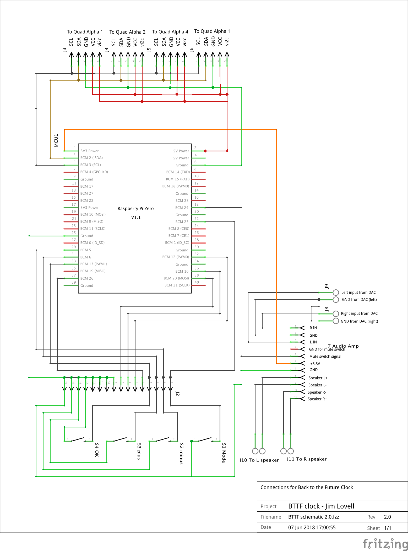
Other connections include the analog audio from the DAC to the amplifier (I used coaxial cable here to help manage noise pickup) and output audio to a pair of small 3W speakers that fit in the enclosure. There are also GPIO connections for the four momentary switches on top of the box and I wired up a momentary button to the hard reset "RUN" pins (see the Additional Connections section on this page). The reset button is mounted out of sight at the back of the enclosure. Here's a diagram showing the connections:
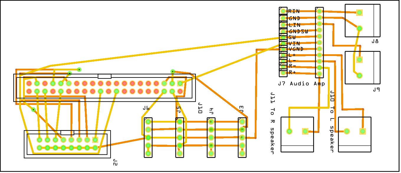
While there is nothing too complicated about the circuit, there is quite a bit of wiring and a breadboard can look like spaghetti pretty quickly. So I designed a PCB to keep it all under control. It's a home-brew single-sided board and I got a friend to help make it. After it was made and wired up, I realised I forgot to include connections for the terminal blocks for the audio and I later made a change to move the audio amp supply from 5V to 3.3V, so it's not ideal and I had to tack on some Veroboard to permit the audio connections. Also, the audio amp board pinouts are at a non-standard separation (they even vary between pins) so the connection for this to the main PCB is a bit horrible with 11 short ~1cm connection wires.
If I made another board, I'd include all these modifications and also change the connector for the four buttons to something a bit nicer. The DAC and Pi would stack right on top, so no ribbon cable needed. Here's how it might look:
The enclosure
I wanted to make an enclosure that looked like one row of the movie time circuit. Three rows of LED displays would have been too much for an alarm clock and would have added significantly to the cost. I thought about making the enclosure out of aluminium but I don't have any skills in that area. I have made quite a few plastic models in my life though, and have some woodworking experience, so decided to make a frame using MDF to mount the LEDs and speakers and fix the perspex to the front, then cover that with a 5-sided styrene box with a bezel on the front, painted in an aluminium metallic spraypaint. The plastic and paint were obtained from a local model shop. I took a close look at the labels on the movie prop and did my best to copy the colours, font type and size. I used Photoshop to build the labels and got them printed as stickers from Redbubble.
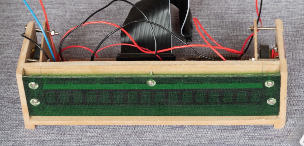
Here's the front of the MDF chassis. The 4 LED backpacks are mounted at the front with green-tinted perspex:
Inside the box. Backpacks all mounted and lines up, Raspberry Pi and custom PCB in, speakers on either side.

Wiring installed and outer shell ready to go on. It was a bit of a squeeze:

Setting up the Raspberry Pi.
I had some compatibility issues with Raspbian Stretch (which may have been solvable if I'd persisted) but Jessie works with it just fine, so I decided to go with that.
I set up the Pi as a headless unit with VNC and SSH access. This could have been done without ever plugging in a keyboard or monitor but I just borrowed the TV and scrounged a keyboard, and got it going headless pretty quickly. From then on, I pretty much used VNC from then on.
My clock code uses Python 2.7.9 and relies on quite a few libraries, listed below. As well as this, I'm running a Flask web server and MQTT for remote control and Shairplay for music streaming. I just followed the on-line installation notes for all of these and had no issues at all. Here are the python libraries and other packages etc I needed to install with links to installation notes or just the command you need to run to get it:
Python libraries
- Adafruit_LED_Backpack
- Rpi.GPIO (apt-get install python-rpi.gpio)
- alsaaudio
- paho.mqtt.client (pip install paho-mqtt)
- flask (apt-get install python-flask)
Other packages etc
- mosquito (apt-get install mosquito)
- shairport
- The Pimoroni web site has some good documentation on setting up the DAC, so I just ran with that.
Software
The clock code was written in Python and uses threading to play the alarm and occasional bleeps in the background without blocking the display updates. I used the ConfigParser library and the config file it maintains is read and wrote by the clock code as well as the Flask web app so that whenever the configuration is changed via the web interface or the clock, it gets synchronised. The clock software also includes an MQTT broker to allow control of the display mode and muting to be controlled remotely. My ulterior motive is eventually to write an iOS app for the remote control but the web interface works well enough for now.
Here's how the clock looks in its various display modes:

While the code isn't pretty to look at it is nice and stable.
The Web app
Here's how the web interface to the clock looks. There's a configure and a control page and they make it much easier to play with without a lot of button mashing :-).

Installing the Software
The attached contains an archive of the software I'm using. Not all of it will work out of the box. In particular, part of the main program sends a request to a web server on out local network to retrieve weather data. The routines that do this will need changing to suit you. Here's a rundown of what you need to do:
- Unpack the zip file in your home directory (probably /home/pi)
- There are five files:
- bttf_clock_release.py - the code that does most of the work (clock display, responds to button presses ect)
- start_clock.sh - run when the Pi has started the Desktop. It starts bttf_clock_release.py and will re-start it if it dies
- bttf.ini - the configuration file which can be modified via thw web app, by editing the file or using the buttons on the clock
- bttf_web_app.py - the Flask web app that serves the web page
- alphanum4_test_myip.py - Run at boot time. Briefly displays the IP address of the clock.
- You will need to edit bttf_clock_release.py and change the functions get_weather and get_bom_weather to suit. See the comments n the code.
-
Add these lines to /etc/rc.local. It will mute the speakers on boot. This assumes you're using gpio on physical pin 18, (which is BCM 24 which is Wiring Pi pin 5! (yes, I know, confusing! See the pinout diagram) ).
/usr/bin/gpio mode 5 out
/usr/bin/gpio write 5 1
-
Install supervisor and put this in the config file /etc/supervisor/supervisord.conf:
[program:flask_app]
command = python bttf_web_app.py
directory = /home/pi
autostart = true
autorestart = true

[program:myip_app]
command = python alphanum4_test_myip.py
directory = /home/pi
autostart = true
autorestart = false
user = pi
When the Pi boots, it will run these two programs.
-
Shairport: put this in the sessioncontrol section of /etc/shairport-sync.conf to mute the speakers when not playing music (Wiring Pi pin 5 assumed)
run_this_before_play_begins = "/usr/bin/gpio write 5 1"; run_this_after_play_ends = "/usr/bin/gpio write 5 0"; -
Edit /home/pi/.config/lxsession/LXDE-pi/autostart and add this line:
@xterm -hold -e /home/pi/start_clock.sh
This starts the main app in a terminal window when the Desktop starts
What next?
There's a Python shareport metadata decoder available so I think I'll add some code to display information like title and artist when music is being played. It would also be quite easy to calculate sunrise and sunset times so that the display can be automatically brightened and dimmed, rather than setting it manually. Maybe adding a radio feature would be fun too. The scrolling display could also be more configurable.

