So we’ve taken a look at what Bluetooth is in our Introduction to Bluetooth tutorial, and hopefully, you’ve found our Choosing a Bluetooth Module For Your Project tutorial useful in deciding which Bluetooth module is right for your project. Now it’s time to really dig in and look at getting them setup for the first time. For this tutorial, we’re going to be looking at using the HC-05 module and configuring it using simple AT commands. Whilst the pin wiring will be specific to the HC-05, the concept is the same, and you should be able to apply the same code and commands to any module you use that works as a TX/RX pipe. Now let’s go ahead and get the HC-05 wired up and ready to go and then we can walk through configuring it.
The Gear:
To follow this tutorial you require:
- 2x Arduino compatible boards (or another platform if you’re happy to tweak some of the code)
- 2x HC-05 or other Bluetooth module that operates as a TX/RX link
- M/M Jumper Wires (we recommend the DFRobot Premium Jumper Wires)
We recommend the HC-05 for almost every use over the HC-06 because the HC-05 is able to operate in both master and slave mode, whereas the HC-06 can only operate in slave mode, and for almost the same price, the HC-05 is the clear winner.
The Circuit:
 For this example, we used two Teensy boards we had lying around, however, because we’ll use SoftSerial in the examples, you can use any Arduino compatible board and we’ll cover the rest below. What this means is rather than having to connect it up to a hardware UART port, we can process the serial information in the library which allows us to use any pins we want to connect to the module at the expense of processing resources. Boards like the Arduino Uno only have a single UART port which is used for the serial communication over USB, so the only option is SoftSerial in that case. For more involved code, you’re better off using dedicated hardware UART to save processing resources. Boards such as Teensy, or bigger Arduino models will have multiple hardware UART ports.
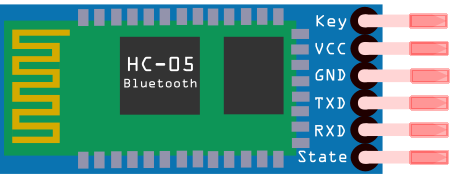
All you need to do is connect each board up to the module that you’re using, paying attention to the power requirements of your board/module. For example, the Teensy boards are 3.3V boards, which works perfectly because we can use the 5V tap to power the HC-05 (has an onboard 3.3V regulator) but the HC-05 data and KEY pins are only 3.3V so we don’t need to use a logic level converter. If your board voltages and module voltages don’t match up, you’ll need to use a logic level converter.
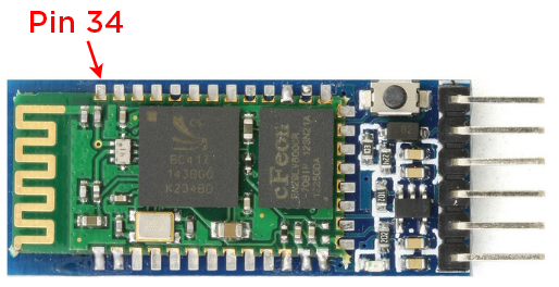
Some HC-05 modules have a small button on module for entering AT command mode, whereas some have pin 34 of the module (KEY) broken out to a header. To put the module into AT command mode, this pin needs to be held high (3.3V) on power up, so if your module has a button, it probably won’t have a ‘KEY’ header pin in which case you don’t need to connect it to anything. If your module does have a button, you can always solder a wire directly to the module to allow you to enable AT command mode in your code.
*EDIT*
It's been brought to our attention that some HC-05 modules don't have a button or a 'KEY' pin. They still have an EN pin which doesn't work for entering the device into the AT Command mode. Unfortunately, with these modules, to enter into AT Command mode, you will need to employ one of the following methods:
- Solder a wire to Pin 34 or the button solder pad closest to the EN pin as shown below. This line becomes the 'KEY' line which you can pull-up before power up to enter into AT mode.

- Solder a wire to each of the button pads, you can short those (or connect them to an external button) to manually enter AT mode.

**Do not solder a wire from the button pads to the EN pin as it will cause your module to lock up**
AT Command Configuration
So now the time has come for us to see if our module works! This method will apply to any Bluetooth module that accepts AT commands, although the process may be a little different on how to get your module into the AT command mode.
So first of all, what are these magical AT commands we keep referencing? Well, they’re an incredibly easy and simple way to find out and set different properties and settings of your module. They’re designed to be sent to the module via the serial connection from your Serial Monitor and display feedback from the commands. For example, if you want to find out the version of Bluetooth that the module is running you can enter ‘AT+VERSION?’. Most commands follow a similar syntax, you enter ‘AT’ (short for ATtention) and then the command (VERSION, ROLE, CMODE etc…) followed by a question to query the state of the setting, or an ‘=’ followed by the parameters to change the setting. It’ll make a bit more sense once we get it up and running and you can play around with it for yourself, so let’s move onto the code we need to do this, it’s incredibly simple.
The AT Config Code:
So as we mentioned above, before we can send any AT commands to the module, we need to put it into the AT command mode. It will vary depending on your module, but for the HC-05 we need to pull pin 34 high during power-up. If your module has a button, connect everything up, but before connecting power to your board, and hence the module, hold the button in, and only release it once you can see the LEDs light up. At this point, rather than rapidly blinking, the LED on the HC-05 will flash every 2 seconds or so. There is a line in the software to pull the KEY pin HIGH however you don’t need to remove this line, just don’t connect anything. If your module doesn’t have a button (or you soldered a wire anyway for software control) then just make sure that the pin you use is the same as defined in the code.
#include <SoftwareSerial.h>

//Change these to whatever pins you're using
SoftwareSerial blueSerial(0, 1); // RX, TX

void setup()
{
  Serial.begin(9600);
  blueSerial.begin(38400);
  pinMode(9, OUTPUT);
  digitalWrite(9, HIGH);
}

void loop()
{
  if (blueSerial.available())
  {
    Serial.write(blueSerial.read());
  }
  if (Serial.available())
  {
    blueSerial.write(Serial.read());
  }
}
Awesome stuff, now to make sure that your module is in the AT command mode, check the LED on the module, it should be slowly blinking every 2 seconds. If not, it’s because power was still connected to the module when the KEY pin was held high. So disconnect power from you board completely, then either hold the button in and connect power or just connect power. You should then see the LED flash slowly indicating that it’s in AT command mode. Good job. Now it’s time to test out our module with some AT commands.
Using AT Commands
The code we just flashed to the microcontroller just echoes whatever is received on one serial port, to the other. This allows us to enter AT commands into the serial monitor. So open up your serial monitor, ensuring that you have the correct COM port, and you’ll need to change the setting in the box saying ‘No line ending’ to ‘Both NL & CR’. Now type ‘AT’ into the text box at the top and press send (or hit Enter). You should get an ‘OK’ in response. If you got that, well done! It means your module is up and running perfectly, and we can begin the configuration for it. If not, go back and double check your wiring. Feel free to play around with some of the other AT commands listed here, just remember that if you use ‘=’ you are setting something, and if you use ‘?’ you and querying the state of a setting.
Now the reason we recommended the HC-05 module is that you can easily configure it to act as either a master or a slave, whereas the HC-06 can only be used as a slave device. Not super handy. So to enable board-to-board communication via Bluetooth, you may recall from our ‘Introduction to Bluetooth’ article that communication may only occur between a master and a slave (with the exception of broadcasting with Bluetooth LE), so we want our master device to send data out to the slave device to do something with. We’ll be using the same code to configure each module so you can just drop the next module into your breadboard setup once you’re finished with the config.
Setting up as Master
To setup a module as the master device, enter the following commands and ensure that you get the correct responses.
AT+RMAAD: Clears any previously paired devices
- returns ‘OK’
AT+ROLE=1: Sets the device to master mode
- returns ‘OK’
AT+RESET: Resets the module, required after changing the previous settings
- returns ‘OK’
After this reset, your module may revert from AT command mode, so you will need to go through the process to set it in command mode again (power reset and/or button).
AT+CMODE=1: Sets the CMODE to allow connection to any device
- returns ‘OK’
AT+INQM=0,5,5: Sets inquiry mode to standard, stops after it’s found 5 devices or after 5 seconds
- returns ‘OK’
AT+PSWD=1234: Sets the password to 1234 which should be set the same on the slave device
- returns ‘OK’
AT+INIT: Start Serial Port Profile, it may return error(17) which just means it’s already loaded
AT+INQ: Search for devices
- returns found devices with the following format: INQ:address,device-mode,signal
Setting up as Slave
To setup a module as the master device, enter the following commands and ensure that you get the correct responses.
AT+RMAAD: Clears any previously paired devices
- returns ‘OK’
AT+ROLE=0: Sets the device to slave mode
- returns ‘OK’
AT+RESET: Resets the module, required after changing the previous settings
- returns ‘OK’
After this reset, your module may revert from AT command mode, so you will need to go through the process to set it in command mode again (power reset and/or button).
AT+CMODE=1: Sets the CMODE to allow connection to any device
-returns ‘OK’
AT+PSWD=1234: Sets the password to 1234 which should be set the same on the slave device
- returns ‘OK’
AT+INIT: Start Serial Port Profile, it may return error(17) which just means it’s already loaded
Awesome sauce! Now we’ve configured out modules to work as a master/slave pair.
Now you don’t actually need to do anything with this address, the two modules will connect without any special authentication by setting them up as we’ve detailed, however you can use that address to connect exclusively to that module. Now connect each module up to your different boards and we’ll look at some simple code to transfer data via Bluetooth (remember that our Bluetooth module is acting as a transparent TX/RX connection).
The Code:
There are two different pieces of code here; one for the transmitter (master) and one for the receiver (slave). All that we’re doing is updating a counter every second and sending it to the other board which then prints the value of the variable to the Serial Monitor. So go ahead and upload the code to the corresponding board, and when you power both of your Bluetooth modules up, they should give an indication of connection. On the HC-05, the LED will flash twice roughly every 2 seconds. Open up the serial monitor for you should see the readout of the variable that is being sent.
Transmitter (master):
#include <SoftwareSerial.h>

SoftwareSerial blueSerial(0,1);

int i;

void setup()
{
  blueSerial.begin(38400);
}

void loop()
{
  blueSerial.write(i);
  i++;
  if(i>255)
  {
    i=0;
  }
  delay(1000);
}
Receiver (slave):
#include <SoftwareSerial.h>

SoftwareSerial blueSerial(0,1);  //RX,TX

void setup()
{
  blueSerial.begin(38400);
  Serial.begin(9600);
}

void loop()
{
  // Read from HC-05 and send new data to Serial Monitor
  if (blueSerial.available())
  {
    Serial.println(blueSerial.read());
  }
}
Woah! You just transferred data over Bluetooth, how cool is that!? Do you feel accomplished? You should. Now you can give your projects the wireless freedom they truly deserve. Check out the rest of our tutorials for more awesome project ideas, and get the Bluetooth conversation going in the comments below. Happy making!

