So we have vertical graphing of voltage and horizontal sweep, but our signal is just going to go bananas on our screen if we don't sweep at the same point in the waveform. That's where triggers come in, allowing us multiple ways to fix our signal to a point on our graph.
Triggers are the method by which an oscilloscope synchronises the voltage and time data of your waveform, enabling you to view your signal fixed to a voltage/time point to analyse it further. Essentially your preset trigger methods are programmed into your scope, you just have to set a condition (sometimes multiple conditions) that your oscilloscope will look out for. When your waveform satisfies that condition, your scope will begin sampling and displaying it central to your screen. Many methods of triggering are available with modern DSOs, the most basic of these is edge triggering.
Before we dive into edge triggering (and all the other types), we are going to introduce trigger modes as briefly and simply as possible.
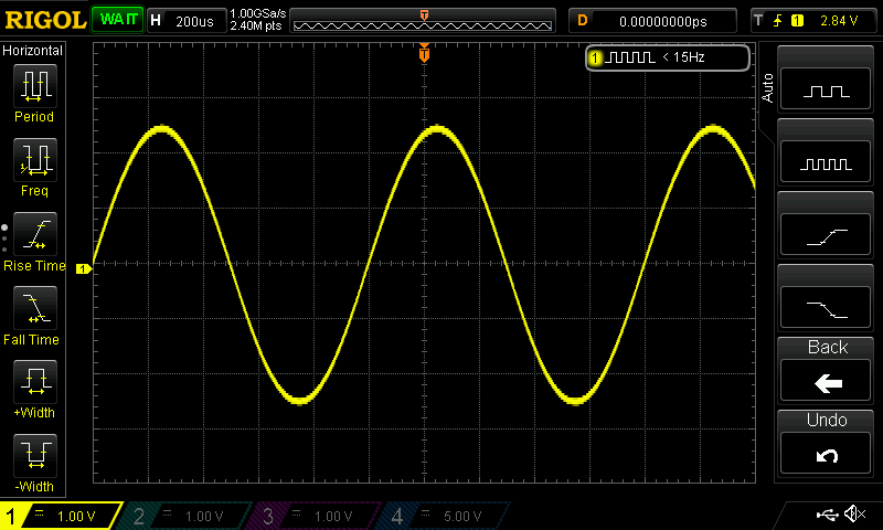
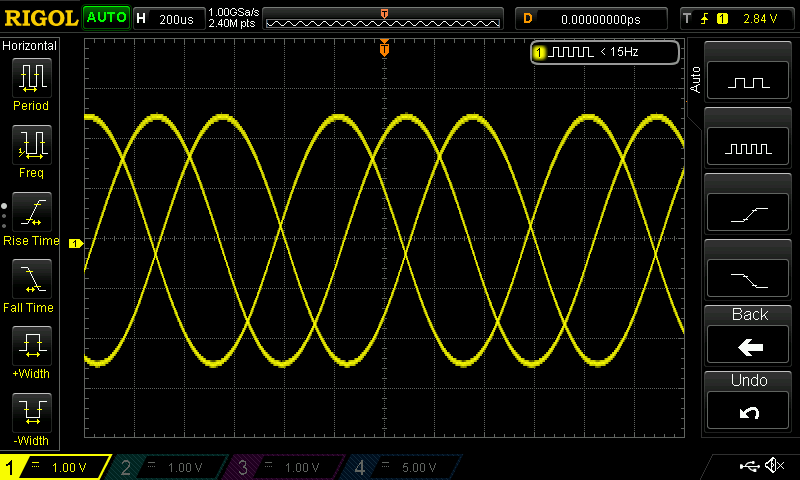
Trigger modes control how your scope will start to sweep your signal. A typical scope will have Auto and Normal modes available (with other options available at higher price/quality points). Normal mode is where the scope will sweep if the signal reaches a certain trigger point. If the signal hasn’t reached this trigger point, the scope will display either nothing (a blank screen) or it will display the last signal read as a static signal on the display (see the first screenshot). Notice that the scope is in a WAIT state (green text, top left corner), as it is waiting to trigger and display a signal. In Auto mode, however, the oscilloscope will sweep regardless of a trigger condition being met. This can result in a crazy, oscillating signal on your display as it isn’t fixed to a set voltage/time trigger. Screenshot 2 is an example of un-triggered Auto mode reading; see how the AUTO symbol is lit up on the top left now as opposed to WAIT.
Now you have some grasp of the 2 main modes associated with triggering, let’s take a closer look at Edge triggering. With edge triggering, you set a voltage threshold level and slope inclination for your scope to begin its sweep when those conditions are met. For example, on our Rigol 1074z, we have the options to set our edge triggers on (see the setting in the top right-hand corner of each of the screenshots):
- The rising portion of the wave (the gradient of your signal is positive), at a particular voltage
- The falling portion of the wave (the gradient of the signal is negative), at a particular voltage
- At either the rising or falling portion of a wave, at a particular voltage.
We use the front panel controls to set the different options as we need them. Using the AUTO function we set the scope to begin sampling when the signal is increasing and passes a threshold of 1.0V. You can see our signal has been fixed on that point in screenshot 2. Edge triggering is the default trigger mode our scope uses and it’s really easy to get a grasp on.
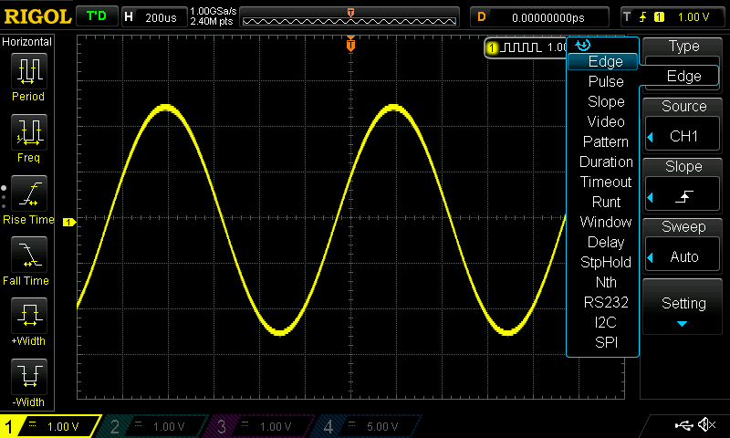
There is a multitude of options apart from edge triggering available with DSOs, as can be seen in screenshot C. I’m going to cover a few of the other options in a similar manner to how we investigated Edge triggering.
Pulse triggering (or width triggering) allows you to specify the trigger condition as a pulse polarity (positive or negative) and width (for our Rigol the range is from 8-10ns). If a signal has a pulse of the specified duration and polarity, your scope will begin sampling them. Pulse triggering can be particularly handy when it comes to investigating serial data streams as you get such a fine horizontal control.
With slope triggering our trigger conditions are a lower and upper voltage threshold (that’s right, two voltage levels) as well as a lower-limit time period for the rising and falling time of the signal. If voltage changes by an amount (see delta V, the delta is quite simply a term used for the amount of change; usually between two values) in a certain time period, the scope will latch at that point. This method is particularly good for capturing triangular and sawtooth waves.
A timeout trigger type allows you to narrow in on ‘dead-times’ within your system. If a signal remains unchanged for a certain amount of time, it may signal issues within the system. A timeout trigger makes it extremely easy to capture this information with your scope. The conditions you define to use this trigger type are:
- A slope inclination (indicated by goes high/goes low at user defined voltage)
- A "timeout" period.
The Runt trigger mode allows you to trigger on signals that cross one voltage threshold but not the second threshold before they return to below the initial threshold. Imagine a smaller signal that could be interfering with the logic in your system. We are able to select positive, negative or either as the polarity condition. We also set a time period qualifier working like a pulse width trigger on top of the typical threshold triggering levels.
A window trigger can be useful to hone in on a signal that has multiple logic levels. With this kind of trigger, you set a ‘window’ using voltage levels and then set the position to trigger at. The positions available are Entering the window, exiting the window or you can set a time domain to frame your window.
The delayed trigger allows you to utilise multiple channels and have the trigger for one channel operate off of a signal read from another channel. In delay triggering you set a Source A and Source B then the rising or falling logic for each source. You then select a delay type from <, >, <>, >< options along with a period of time (these options work just as you would expect). Each of the delay types has corresponding time setting that become available when you select them, as in the < type only requires an upper limit whereas the <> type will require both an upper and lower limit.
While there are a few more options that you can use for trigger types with your oscilloscope (Video, Pattern, Nth type), this article is for beginners and we thought it best to not overwhelm anyone. The methods discussed above should get you comfortable with the basic skills in triggering.

