Today we're pulling out the breadboard, getting up and running with an RTC module then finishing up by making ourselves a clock that will keep the correct time even when we pull the plug. To achieve this we will be combining three main components, an RTC (real-time clock), the DFRobot Liquid Crystal 1602 Display, and the Italian micro-controller stallion that is the Arduino Uno R3. The code is fully functional and with the three buttons, you can change the date and time to exactly what you want.
The Arduino Uno is perfect for a job like this as we can tell it exactly what to do and it will perform that job every time and the instant it turns on. It also has great support for all kinds of maker hardware so you can use it for this project then pull it out, reflash the code and throw it into a whole different setup doing a completely different task. The DFRobot Gravity RTC clock used here will function for 5 years from when the button battery is inserted providing accurate time for that whole length of time. This has the new version DS1307 RTC module which adopts a high precision crystal oscillator. Testing conducted shows the time error is only about 1 second in 24 hours (for comparison the average time error of Mechanical Watches is about 20s). For this setup here I used a DFRobot Gravity LCD Display. This one is neat because the contrast is automatically done (no fiddling with a potentiometer required) and it comes backlit out of the box. Below are the contents of this guide.
- What You Need for Clock and Why These Components were Chosen
- RTC with Arduino Uno R3 Introduction
- Schematic for Clock
- How a Breadboard Works and Zooming in on the Clock's Breadboard
- Set up Arduino IDE for Clock
- The Functional (and a Little Rough) Code for Arduino IDE to Run the Clock
- Success and Where to Now!
- Downloads and Acknowledgment
Below is an image of the final result of this guide! A clock that will keep time even when the power is pulled from it. One that you can adjust the time to whatever you desire using the buttons on the board.

With all the code already downloaded to the Arduino Uno R3, this would make for a very fun breadboarding experiment/lesson with a very rewarding conclusion. It is very tactile process and would consistently tell the correct time even when powered down. I can see it being implemented as a school lesson over a double period. I also see this as a great springboard to create your own clock creations with Arduino using other display methods (like Nixie Tubes) or improving the code to creating new features (such as multiple clocks overlayed running for different locations in the world).
If your hardware used is slightly different a quick alteration to the code can fix you right up. As always if you have got any questions, queries, or things you'd like to see added please let us know your thoughts!
What You Need For Clock and Why These Components Were Chosen
The reason the three main components were chosen is twofold. All the electronics will function at their best at 5 Volts. All the electronics communicate with each other using I2C protocol. That may sound confusing but really it just means they all talk in the same language and eat the same food so we won’t need any extra hardware acting as a translator. Thus making for a simpler build. Also for all the features talked about in the introduction.
To give an idea of the size of these objects next to each other below is an image of all the major components required to make this clock a reality.

Below is a list of everything you will need to replicate this with images attached.

- A to B Peripheral Cable (How we get power into our clock and Code into the Arduino)

- DFRobot Gravity RTC (Real Time Clock)
")
- DFRobot Gravity I2C LCD1602 Display

- Jumper Wires of Various Colours Male to Male (Good Quality jumper wires make Good Quality Connection. I have spent too long baffled by circuits that don't work only to realise much too far down the lane that it is just my bad jumper wires not sending the electronics signals that are the problem. Please learn from me and do not go down that same road!)

- Breadboard. A Good Breadboard makes for a happy maker. Happy Maker Happy Life.

- Three Resistors (~330 Olms)


RTC With Arduino Uno Introduction
So let us start by connecting up the DFRobot Gravity RTC to the Arduino Uno R3. I have been connecting everything using the JST white connectors and adding jumper cables to the ends of those connections. Learn a whole bunch about all types of electronic connectors here. You can see this in the image below where I have pulled out the SDA connection from the wires. Make your life easy by always using consistent colour for wires. Red is live, Black is ground is the standard attitude. You could solder all these connections together and use a Protoboard if you desire something substantially more permanent.

Now let us connect the other end of these jumper wires to the Arduino. The SCL pin needs to connect to the C on the RTC and the SDA pin needs to connect to the D on the RTC. The Black wire needs to go to a Ground Pin on the Arduino Uno and the Power pin needs to go to the 5V Pin on the Arduino Uno. You can see exactly what I mean in the image below.

With everything attached lets us now plug the A to B Peripheral Cable into the Arduino Uno R3 (as you can see above) and connect the other side to a USB port on your computer. This means we can write code to the Arduino Uno R3 using the Arduino IDE. A great introduction to the Arduino IDE can be created by Christian can be found at the bottom of the page here and another fantastic guide completed on Arduino IDE by Aidan here.
Arduino IDE is a lightweight programming package so it doesn’t come with everything we need to get this RTC to work but it is very easy to add libraries to the system. After downloading the Arduino IDE from this location onto your computer we will need to install one libraries to increase the functionality of this software. Open up the software, click on the sketch drop-down menu and then click on | Manage Libraries | setting, exactly like in the image below.

This will open up a Library Manager window. In this window type into the search bar | RTClib |, see the image below of this happening. Then click install making sure to select the newest version. Depending on your Real-time Clock used in the project you may need to use a different library or alter the Code for the clock. So long as your running a Real-time Clock that has a DS1307 chip inside it this code will work fine.

Having done the library requirements are sorted and we can start coding. Copy and Paste the below code into the Arduino IDE coding section (deleting anything that was written in there beforehand). Then Save, Verify, and Upload the code to your Arduino Uno R3. Looking at the code you can see we are including two libraries, one being the library we just added. Next, you can see the exact chip that is on the DFRobot being referenced which is the RTC DS1307. We can see next an array is set up to represent the 7 days and 12 being the maximum amount of characters in the words for the day of the week. We then decide the Baud rate. Baud rate refers to the number of signal or symbol changes that occur per second (bits per second). After this some If statements so that way if the RTC is not correctly connected it will display error settings and if it is correctly connected it will print a whole bunch of information to the Serial Monitor about what it thinks the date, time, and day is. A sweet bit of code, basically the Hello World for RTC devices.
// Date and time functions using a DS1307 RTC connected via I2C and Wire lib
#include "RTClib.h"

RTC_DS1307 rtc;

char daysOfTheWeek[7][12] = {"Sunday", "Monday", "Tuesday", "Wednesday", "Thursday", "Friday", "Saturday"};

void setup () {
  Serial.begin(57600);

#ifndef ESP8266
  while (!Serial); // wait for serial port to connect. Needed for native USB
#endif

  if (! rtc.begin()) {
    Serial.println("Couldn't find RTC");
    Serial.flush();
    abort();
  }

  if (! rtc.isrunning()) {
    Serial.println("RTC is NOT running, let's set the time!");
    // When time needs to be set on a new device, or after a power loss, the
    // following line sets the RTC to the date & time this sketch was compiled
    rtc.adjust(DateTime(F(__DATE__), F(__TIME__)));
    // This line sets the RTC with an explicit date & time, for example to set
    // January 21, 2014 at 3am you would call:
    // rtc.adjust(DateTime(2014, 1, 21, 3, 0, 0));
  }

  // When time needs to be re-set on a previously configured device, the
  // following line sets the RTC to the date & time this sketch was compiled
  // rtc.adjust(DateTime(F(__DATE__), F(__TIME__)));
  // This line sets the RTC with an explicit date & time, for example to set
  // January 21, 2014 at 3am you would call:
  // rtc.adjust(DateTime(2014, 1, 21, 3, 0, 0));
}

void loop () {
    DateTime now = rtc.now();

    Serial.print(now.year(), DEC);
    Serial.print('/');
    Serial.print(now.month(), DEC);
    Serial.print('/');
    Serial.print(now.day(), DEC);
    Serial.print(" (");
    Serial.print(daysOfTheWeek[now.dayOfTheWeek()]);
    Serial.print(") ");
    Serial.print(now.hour(), DEC);
    Serial.print(':');
    Serial.print(now.minute(), DEC);
    Serial.print(':');
    Serial.print(now.second(), DEC);
    Serial.println();

    Serial.print(" since midnight 1/1/1970 = ");
    Serial.print(now.unixtime());
    Serial.print("s = ");
    Serial.print(now.unixtime() / 86400L);
    Serial.println("d");

    // calculate a date which is 7 days, 12 hours, 30 minutes, and 6 seconds into the future
    DateTime future (now + TimeSpan(7,12,30,6));

    Serial.print(" now + 7d + 12h + 30m + 6s: ");
    Serial.print(future.year(), DEC);
    Serial.print('/');
    Serial.print(future.month(), DEC);
    Serial.print('/');
    Serial.print(future.day(), DEC);
    Serial.print(' ');
    Serial.print(future.hour(), DEC);
    Serial.print(':');
    Serial.print(future.minute(), DEC);
    Serial.print(':');
    Serial.print(future.second(), DEC);
    Serial.println();

    Serial.println();
    delay(3000);
}
Having done this you can then open up the Serial Monitor using the Tool drop-down menu, see image below. This opens up another window which you can see in the image below which will be receiving Date and Time information from the DFRobot RTC. Nicely done! It is now working. If the messages being written on the Serial Monitor come back looking like | ⸮⸮⸮⸮x⸮`f⸮⸮⸮ | then alter the Baud rate (see highlighted in a red box below).

Schematics for Clock
Below is the breadboarding schematic used to create this clock. When everything is plugged in the same way as below you can then power up the Arduino UNO using the A-B Peripheral Cable and connecting it to a USB port in your computer. The 5 Volt out pin from the Arduino Uno is placed on the power rail to supply power to each component. Each component shares the common ground. Common Ground comes from an Arduino Uno ground Pin which goes to the farthest edge rail. The three SCL wires needed for the I2C communication between the parts are connected along a column in the middle of the breadboard. The same is done for the three SDA Pins. These are required for the I2C communication between these components to function correctly. The Buttons are connected to Pin 6, 7 and 8 on the Arduino (to correlate with the code created for this clock). We can see all the hardware has ground wires going to the top most rail. Each of the buttons also is connected to the common ground through a resistor. The resistor is there to prevent the short by limiting the current flowing through too quickly. In this case I have used a 330 Olm resistors. In this configuration with the resistor going to ground is referred to as the Pull Down. If the resistor was connecting to the 5 volt rail instead this would be called a pulled up.

Below is what it looks like in real life when it has all been connected up. Definitely take a moment now to check all the connections on your set up. At this stage when you plug the Arduino Uno R3 into USB nothing will appear on the LCD screen (or a whole bunch of black bars may pop up). This is all good, you just need to get the code into the Arduino Uno R3 for it to work like the image below.

To enhance understand I believe it worthwhile to provide close-up images of the DFRobot RTC Connections and DFRobot 1602LCD Connection Valuable. Make sure all the connections you have coming off the devices are going to the correct corresponding location. The LCD and the RTC components here have slightly different names for their connections. The SCL needs to connect to the C and the SDA needs to connect to the D. You can see exactly what I mean in the image below.

How a Breadboard Works and Zooming in on the Clock's Breadboard
Some background knowledge on how a breadboard functions would be immensely useful. Knowledge such as how the power rails function, what terminal strips are, and how the ravine in the centre can prevent shorting are all valuable. The champion Sam did a great rundown on breadboards and how to use them found here.

Two points I will highlight here. The Power rails run vertically along the sides of full-sized breadboards. By connecting power to one socket the whole row of the rail will be powered electrically. See below a close up of our bread board with the power rail that has been given electricity (5 Volts by the Arduino Uno). By looking across the Power rail we can see it supplies the electricity for each component in the system. All componentry needs to share a common ground which is achieved using the furthest edge rail using the same concept.

The other section of the clock's breadboard I will highlight is how terminal strips function. Sections in the middle of the breadboard are all connected together if they are in the same column of dots. For example, in this clock breadboard there are a number of connections done this way. For this setup for the I2C communication to go ahead, we need to connect all the SCL and SDA pins of the electronics together which you can see here. The SDA pins will send the data and receive the data. The SCL is the clock line that syncs all the data transfers correctly so there is no confusion. For this set up I have used a green wire for the SCL and a blue wire for the SDA. You can see that these wires all come together in the same column. 3 wires for SCL, one from the Arduino, one from the RTC, and one from the LCD Display, and the same for the SDA. When you are in the middle of the breadboard all the columns will be connected electrically. So, by connecting the Blues wires all in a column like this it is the same as soldering all the wires together, except this way it is far easier to pull apart.
Below show an image of connections that have been done this way highlighting the connections with arrows and transparent colour.

Set up Arduino IDE For Clock
Below is the process for the Arduino IDE for the clock. After downloading the Arduino IDE from this location onto your computer we will need to install three libraries to increase the functionality of this software using a similar method as before. Open up the software, click on the sketch drop-down menu and then click on | Manage Libraries | setting, exactly like in the image below.
This will open up a Library Manager window. In this, we will type in the search bar | RTClib |, see the image below of this happening. Then click install making sure to select the newest version. Having done this one library requirement is sorted, thus two more libraries to go. Depending on your Real-time Clock used in the project you may need to use a different library or alter the Code for the clock. So long as your running a Real-time Clock that has a DS1307 chip inside it this code will work fine.
Next type in Liquid Crystal_I2C into the Library Manager search bar. There will be lots of similar libraries but the one you must install is the one created by Frank de Brabander. See the image below for what this will look like, typing the _ will help this library appear.

Finally, you will need to include a library through a zip file. This will be done by pressing the Add .Zip Library button. See the image below for the location of this option. The library you need to download to your computer can be found via this location or at the bottom of the page. With it downloaded to your computer you can then navigate using the sketch top-down menu like in the image below. You will then be able to find the DFRobot_LCD.h Zip file and by selecting this you will have imported all the functionality you need to your code.

The Functional (and a Little Rough) Code for Arduino IDE to Run the Clock
Below you can find the Arduino code used for this clock. Copy and paste it into your Arduino IDE or download it using the link below. You will notice the code has been adequately commented so that personal changes and alterations with a little bit of practice in this language can be totally achieved.
/* :Project:Clock_Set_Date_Time :Author: Tiziano Bianchettin, Tim and Ollie :Date: 18/05/2021 :Revision: 3 :License: Public Domain thanks to: http://arduinoenonsolo.blogspot.it/2012/12/orologio-con-arduino-e-il-ds1307.html http://www.mauroalfieri.it/ http://www.danielealberti.it/ http://www.maffucci.it/ My electronics laboratory professor "Perito Carli" New revision has allowed this clock to be used with DFRobot LCD 1602 Screen. It has also incorperated Debounce variable to make the button clicking more satisfactory It has also altered the method in which the menus are displayed so remove the visable 1 second refresh rate that existed before The code may be rough by it is defintely functional. */ //************libraries**************// #include#include #include "DFRobot_LCD.h" #include //***************Hardware being used*********************// DFRobot_LCD lcd(16,2); // Display I2C 16 x 2 RTC_DS1307 RTC; //************Button that will be used on Arduino Pins*****************// int P1=6; // Button SET MENU' int P2=7; // Button + int P3=8; // Button - //************Variables Used Including New Debounce Variable**************// int hourupg; int minupg; int yearupg; int monthupg; int dayupg; int menu=0; const int debounce = 35; void setup() { lcd.init(); lcd.clear(); pinMode(P1,INPUT); pinMode(P2,INPUT); pinMode(P3,INPUT); Serial.begin(9600); Wire.begin(); RTC.begin(); if (! RTC.isrunning()) { Serial.println("RTC is NOT running!"); // Set the date and time at compile time RTC.adjust(DateTime(__DATE__, __TIME__)); } // RTC.adjust(DateTime(__DATE__, __TIME__)); //removing "//" to adjust the time // The default display shows the date and time } void loop() { // in which subroutine should we go? if (menu==0) { DisplayDateTime(); // void DisplayDateTime } if (menu==1) { DisplaySetHour(); } if (menu==2) { DisplaySetMinute(); } if (menu==3) { DisplaySetYear(); } if (menu==4) { DisplaySetMonth(); } if (menu==5) { DisplaySetDay(); } if (menu==6) { StoreAgg(); //delay(500); menu=0; } delay(50); } void DisplayDateTime () { // We show the current date and time DateTime now = RTC.now(); if(digitalRead(P1)){ menu=1; delay(debounce); } lcd.setCursor(0, 1); lcd.print("Hour:"); if (now.hour()<=9) { lcd.print("0"); } lcd.print(now.hour(), DEC); hourupg=now.hour(); lcd.print(":"); if (now.minute()<=9) { lcd.print("0"); } lcd.print(now.minute(), DEC); minupg=now.minute(); lcd.print(":"); if(digitalRead(P1)){ menu=1; delay(debounce); } if (now.second()<=9) { lcd.print("0"); } lcd.print(now.second(), DEC); lcd.setCursor(0, 0); lcd.print("Date: "); if (now.day()<=9) { lcd.print("0"); } lcd.print(now.day(), DEC); dayupg=now.day(); lcd.print("/"); if(digitalRead(P1)){ menu=1; delay(debounce); } if (now.month()<=9) { lcd.print("0"); } lcd.print(now.month(), DEC); monthupg=now.month(); lcd.print("/"); lcd.print(now.year(), DEC); yearupg=now.year(); if(digitalRead(P1)){ menu=1; delay(debounce); } } void DisplaySetHour() { // time setting lcd.clear(); DateTime now = RTC.now(); lcd.setCursor(0,0); lcd.print("Set Hour:"); lcd.setCursor(0,1); lcd.print(hourupg,DEC); while(!digitalRead(P1)){ if(digitalRead(P2)==HIGH) { if(hourupg==23) { hourupg=0; } else { hourupg=hourupg+1; } delay(debounce); } if(digitalRead(P3)==HIGH) { if(hourupg==0) { hourupg=23; } else { hourupg=hourupg-1; } delay(debounce); } DateTime now = RTC.now(); lcd.setCursor(0,0); lcd.print("Set Hour:"); lcd.setCursor(0,1); lcd.print(hourupg,DEC); lcd.print(" "); } menu=2; delay(debounce); } void DisplaySetMinute() { // Setting the minutes lcd.clear(); lcd.setCursor(0,0); lcd.print("Set Minutes:"); lcd.setCursor(0,1); lcd.print(minupg,DEC); while(!digitalRead(P1)){ if(digitalRead(P2)==HIGH) { if (minupg==59) { minupg=0; } else { minupg=minupg+1; } delay(debounce); } if(digitalRead(P3)==HIGH) { if (minupg==0) { minupg=59; } else { minupg=minupg-1; } delay(debounce); } lcd.setCursor(0,0); lcd.print("Set Minutes:"); lcd.setCursor(0,1); lcd.print(minupg,DEC); lcd.print(" "); //delay(200); } menu=3; delay(debounce); } void DisplaySetYear() { // setting the year lcd.clear(); lcd.setCursor(0,0); lcd.print("Set Year:"); lcd.setCursor(0,1); lcd.print(yearupg,DEC); while(!digitalRead(P1)){ if(digitalRead(P2)==HIGH) { yearupg=yearupg+1; } if(digitalRead(P3)==HIGH) { yearupg=yearupg-1; } delay(debounce); lcd.setCursor(0,0); lcd.print("Set Year:"); lcd.setCursor(0,1); lcd.print(yearupg,DEC); lcd.print(" "); } menu=4; delay(debounce); } void DisplaySetMonth() { // Setting the month lcd.clear(); lcd.setCursor(0,0); lcd.print("Set Month:"); lcd.setCursor(0,1); lcd.print(monthupg,DEC); while(!digitalRead(P1)){ if(digitalRead(P2)==HIGH) { if (monthupg==12) { monthupg=1; } else { monthupg=monthupg+1; } } if(digitalRead(P3)==HIGH) { if (monthupg==1) { monthupg=12; } else { monthupg=monthupg-1; } } lcd.setCursor(0,0); lcd.print("Set Month:"); lcd.setCursor(0,1); lcd.print(monthupg,DEC); lcd.print(" "); delay(debounce); } menu=5; delay(debounce); //delay(200); } void DisplaySetDay() { // Setting the day lcd.clear(); delay(debounce); while(!digitalRead(P1)){ if(digitalRead(P2)==HIGH) { if (dayupg==31) { dayupg=1; } else { dayupg=dayupg+1; } } if(digitalRead(P3)==HIGH) { if (dayupg==1) { dayupg=31; } else { dayupg=dayupg-1; } } lcd.setCursor(0,0); lcd.print("Set Day:"); lcd.setCursor(0,1); lcd.print(dayupg,DEC); lcd.print(" "); delay(debounce); } menu=6; delay(debounce); } void StoreAgg() { // Variable saving lcd.clear(); lcd.setCursor(0,0); lcd.print("SAVING IN"); lcd.setCursor(0,1); lcd.print("PROGRESS"); RTC.adjust(DateTime(yearupg,monthupg,dayupg,hourupg,minupg,0)); delay(200); }
Verify the program using the button seen indicated in red in the image below. If this goes through smoothly without a hitch it means all the libraries necessary have been incorporated into the Arduino IDE. You can now connect up your Arduino Uno to your computer using the A to B Peripheral Cord. Then Click that little right-facing arrow (indicated in Pink in the image below) to Upload the code to your Arduino Uno. If everything is connected correctly all should run and work and you will have yourself a working clock!

Success and Where to Now
With all the code already downloaded to the Arduino, this would make for a very fun breadboarding experiment with a very rewarding conclusion. It is very tactile and would consistently tell the correct time even when powered down. I can see it being implemented as a school lesson over a double period. I also see this as a great springboard to create your own clock creations with Arduino using other display methods (like Nixie Tubes) or improving the code to creating new features (such as multiple clocks running for different locations in the world). If you want to take this project to a more permanent set up a great guide by Sam talking about breadboards vs stripboards vs Perfboard can be found here which are all excellent potential avenues to increase the permanency of this clock.


Downloads and Acknowledgement
Below you can find attached the Code for the Arduino IDE all ready to go and the ZIP file for the Library required by the Arduino IDE to run the code correctly. For a demonstration of the clock see the future video! I must also pay homage to this clock project created by Tittiamo which helped me immensely to create this.
Attachment - Code_and_Zip_Library_Needed.zip
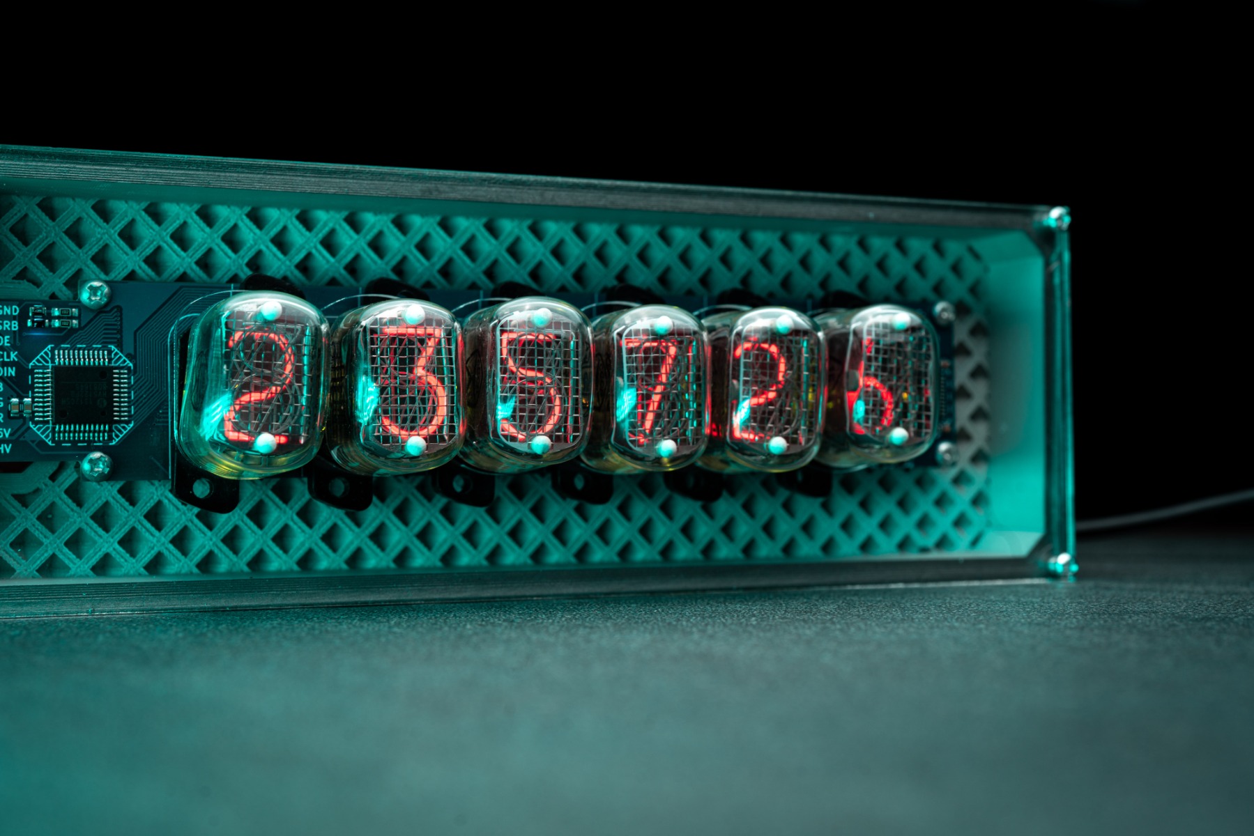
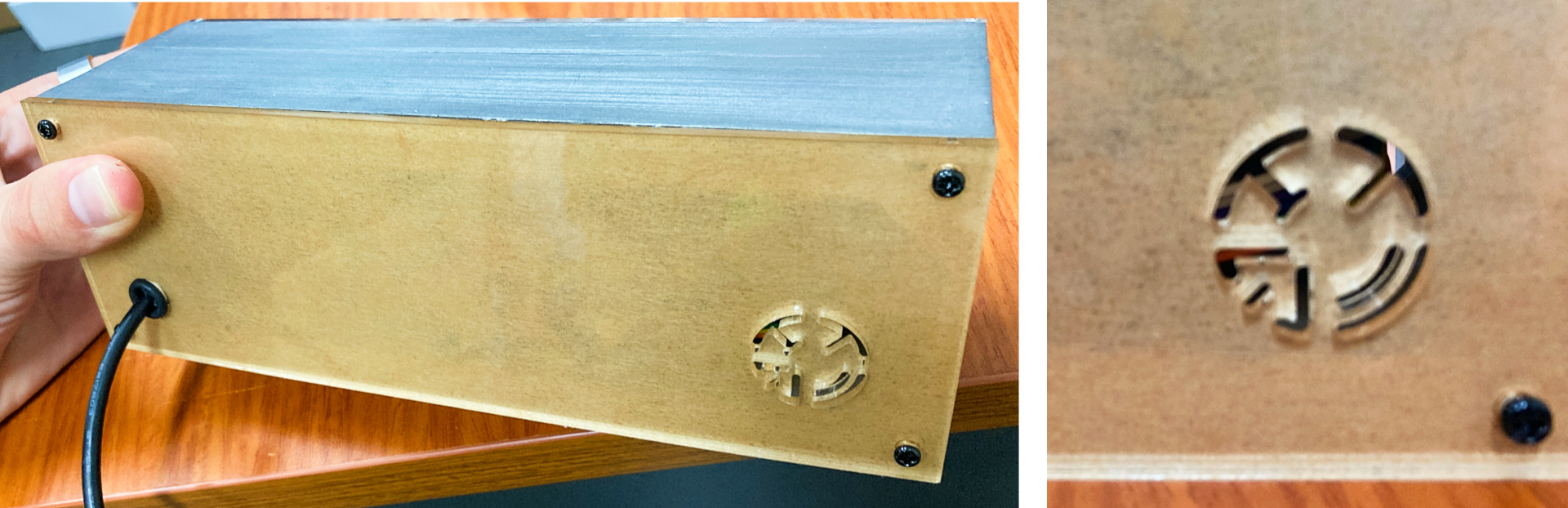
Update
I finished up the Nixie Clock, I'll pop some images down below of it running. The only hardware change was using an Arduino Micro instead of Arduino UNO to save some space. Big thanks to Doayee for the Driver board and Big thanks to Ukraine for supplying me with the new Old Stock IN12B Nixie Tubes.