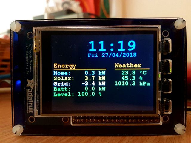
This project uses a Raspberry Pi and TFT display panel to provide a desk clock that also monitors our Home Solar and Battery system, and the weather, in one neat unit.
We recently installed a Solar Panel system and a Tesla Powerwall2 at our home, and we have been very happy with the system.
However, one aspect that I thought could be improved was real-time monitoring of the system. While the Tesla app for mobiles/tablets does a good job of showing exactly what is happening, I wanted something that was always on so I could see the status "at a glance", rather than having to get my phone out of my pocket (the troubles of modern life!). I also was in need of a clock on my desk and wanted a small project to spend some time on, so this project was the result.
While the project presented here is currently specific to my home setup, I believe it is simple enough to show "what can be done" so that if you have other items that you want to monitor you should be able to modify the code to suit. Several of the elements in the code can be modified to customise the unit as well.
Parts List
- A Raspberry Pi Board (I used the 3B, but there's no reason the B won't work)
- Adafruit 2.8" TFT with resistive touchscreen
- PiTFT Pibow Kit for Pi 2 / B / Pi 3
- 5V plug pack
Tools
This project can be constructed with no tools at all if you decide to power the Pi via the normal USB power input socket.
Wiring
The Adafruit 2.8" TFT plugs straight into the GPIO header on the Raspberry Pi, and the PiTFT Pibow kit provides a small "spanner" to tighten the nuts that hold the case together, so it is possible to construct this project without any wiring at all.
However, I preferred to provide power to my unit via the GPIO header and avoid having a USB connector sticking out of the top of the case.
To achieve this I salvaged a small header socket from some old PC equipment that was scheduled for the recycling station, and connected it to the "spare" GPIO header on the TFT display, using pins 2 and 6 for 5V and 0V respectively.

*CAUTION*
Note that powering Pi models this way is possible, but this bypasses some of the protection circuits built into the Pi, so damage can result to the Pi if the power supply is not reliable.
Construction
All that is required is to follow the assembly instructions that come on the Pibow packaging to assemble the case around the Pi.
To aid in alignment, I placed the case screws into layer 0 from behind. This made each successive layer more stable as the case was assembled. After all the layers were in place, the screws were removed one at a time and reinserted from the front to provide a better appearance.
Start with layers 0, 1 and 2, then place the Pi onto these layers. If you want to power the Pi via the GPIO header, then you will need to decide how to get the power cord into the case. I carefully removed the tab that went between the ethernet socket and the USB sockets from layer 3, which allowed the power cable to run between these devices. 

Continue to install layers 3 through to 8 inclusive.

After adding layer 8 to the stack, fit the TFT onto the PI, remembering to connect the power cable to the TFT header if required. The TFT is nicely supported by 4 tabs on layer 8 of the Pibow kit.
Finish by placing the remaining 2 layers onto the stack, then fit the nuts onto the screws and tighten them - not too much though. If you placed the screws through the back plate to aid alignment and would prefer to see the screw heads rather than the nuts on the front of the case, then carefully slide out one screw at a time, reverse it, and fit the nut at the rear of the case.
The final assembly looks rather neat in my opinion.
Pi Setup
Start with a standard Raspbian image. I used the current "Stretch" image from 18 April 2018. Download the image, and write it to an SD card as per normal.
Next, setup the Pi to operate "headless" - i.e. without a keyboard or screen. Follow the Core Electronics tutorial if you need assistance with this here: https://core-electronics.com.au/tutorials/raspberry-pi-zerow-headless-wifi-setup.html
Once the Pi is operating via WiFi and has SSH capability, connect via SSH and carry out setup tasks using the command "sudo raspi-config"
I always carry out the following steps with any new Pi:
- Give the Pi a unique name on the network. For this project, I used the name "system-mon"
- Establish a new password for the user "pi".
- Ensure for this project that the Pi is set for "Console Autologin"
- Establish the correct Localisation Options - especially the correct Timezone
Restart the Pi (sudo reboot from the SSH terminal), after it has restarted connect again via SSH then type "date" at the command prompt to ensure the date and time are correct on the system. Now carry out the next steps:
Get the TFT Display working
Enable the TFT screen by following the Adafruit instructions here: https://learn.adafruit.com/adafruit-pitft-28-inch-resistive-touchscreen-display-raspberry-pi/easy-install-2
When following these steps, ensure you use the Installer Script - it makes the task of getting the TFT working very easy.
To enable the TFT with the buttons on the right (as shown in my project) the screen rotation is 90 degrees landscape (option 1). Also, answer "yes" to the question "Would you like the console to appear on the PiTFT display"
After this, use "sudo reboot" to restart the Pi and the text console should appear on the TFT.
Enable access to network file shares
For this project, I needed to access weather data from a file share on my home network. The weather data is saved there by a different system, this unit simply accesses the saved data to display it.
The file share is available via NFS as well as via normal Windows protocols, so for accessing these shares from the Pis, I use NFS.
Once again from the SSH terminal, type the following commands:
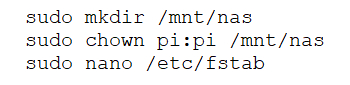
When you edit the fstab file, make sure you don't make any changes to the existing entries in this file unless you know exactly what you are doing. This file is used during startup of the Pi to access the file systems the Pi needs to operate, so if you make changes that prevent the Pi from accessing needed files, it will fail to boot and you will be required to start with a new SD Card image.
Add the following as the last line of the fstab file (as a single line):

I found these values online while searching for information on how to mount NFS shares via fstab, but can't remember where.
Your setup will almost certainly be different. The start of the line "nas:/sharedfiles/PiData" specifies the system to connect to ("nas" in this case) and the share to access ("/sharedfiles/PiData"). The next section "/mnt/nas" is where to make the network shared files appear in the Pi's file system. The remainder of the line I copied from the Internet and I can't give details on what each option does.
After you have added the line, press Ctrl-X, answer "Yes" and accept the offered filename.
Now, type "sudo mount -a" from the command prompt to load the fstab and mount the shared files - you should not get any errors, and if you type "ls /mnt/nas" you should see the shared files listed.
Copy the project files to the Pi
Copy the files SystemMon.py and setupbacklight.sh to /home/pi on the Pi. You can use an SCP client like WinSCP to do this easily from a Windows PC once SSH is working.
Modify the /home/pi/.bashrc file
Type "nano .bashrc", and add the following lines as the last lines in the file:
 if [ -n "SSH_CLIENT" ]; then
  echo SSH Session - not running SystemMonSleep script
else
  /home/pi/setupbacklight.sh
  python3 /home/pi/SystemMonSleep.py
fi
These lines perform the following: Check if you are logging in via an SSH client. If you are; then echo the message "SSH session - not running SystemMon script" to the terminal Otherwise (i.e. this is NOT an SSH session) run the command /home/pi/setupbacklight.sh (to allow control of the backlight level) run the SystemMon.py script
That's it. Restart the Pi, and the TFT should display the Time, Date, Energy and Weather information on the TFT display. Also, if you now SSH to the Pi, you should reach the normal command line, but also see the message "SSH session - not running SystemMonSleep script" displayed.
Code
The code for the project is given in the ZIP files below.
setupbacklight.sh
The file "setupbacklight.sh" is a bash shell script that simply uses the inbuilt gpio program to establish PWM mode for BCM pin 18 (GPIO Pin 1) prior to running the python code for the main program.
SystemMonSleep.py
The main program is SystemMonSleep.py, and I have included comments in the code to explain the sections of code, please refer to these as well as this explanation. Please also be aware that the program requires various parameters to be modified to suit your own installation.
The main program is broken down into the following broad sections:
- Lines 1 - 72 load libraries and define 2 routines used regularly to collect external data
- Line 80 needs to be modified to specify the IP address of your Powerwall gateway
- Line 85 specifies the location that the Weather data can be found from. This specifies the actual file containing the data, not just a shared folder
- Line 92 gives a value that affects how slowly or quickly the colours cycle through for the time and date. A lower number gives more colours, so the colour cycles through slower. Conversely, a higher number makes the colours cycle through quicker.
- Lines 96 and 97 set the Start and End times for the display to automatically set itself to the lowest backlight level (by default off - but this is adjustable, see the point (g) below). Between these times if you alter the backlight level from one of the buttons, it will stay at the new level for about 1 minute, then revert to the lowest level again.
- Line 101 specifies the time of day for the backlight to automatically switch to the second lowest level. If the backlight is altered to a higher or lower level manually after this time, it will not change back.
- Lines 105 - 108 set the 4 backlight levels to use when each of the 4 buttons is pressed. These are percentage values of full, and I find the values 100, 50, 5 and 0 work for me. Setting the backlight to 0 turns off the display and I use this is as the value between midnight and 07:30. No point displaying anything when I'm not up to look at it.
- Lines 110 - 201 establish other variables, and setup the function of the unit prior to the main program loop.
- Lines 204 - 444 are the main loop of the program which runs continuously, doing the following:
- Blank the display
- Get the current time
- Work out if new Energy or Weather data should be collected
- Calculate new colour values for the Time and Date
- Format every piece of text for the display
- Calculate the locations of each piece of text
- Check if one of the push buttons has been pressed and if so alter the desired backlighting level
- Check if the touch screen was pressed. If so, exit the program.
- Check if the backlight should be dimmed because it is the specified time for this to occur
- Check if the backlight should be put to sleep, or if it should be woken up
- If the backlight level is set to 0, don't bother displaying anything
- Otherwise, write the text to the screen
- Set the backlight control pin to the desired value
- Flip the display to display the new screen of data
- Go off and get new Energy or Weather data if required
- Suspend operation of the program for about 200 milliseconds to keep CPU use low and give other tasks a chance to run
That's roughly how the code works. If you read through the code and use online resources to get explanations of any code you are unfamiliar with, it should be straightforward how it works.
Have fun building your own unit!

