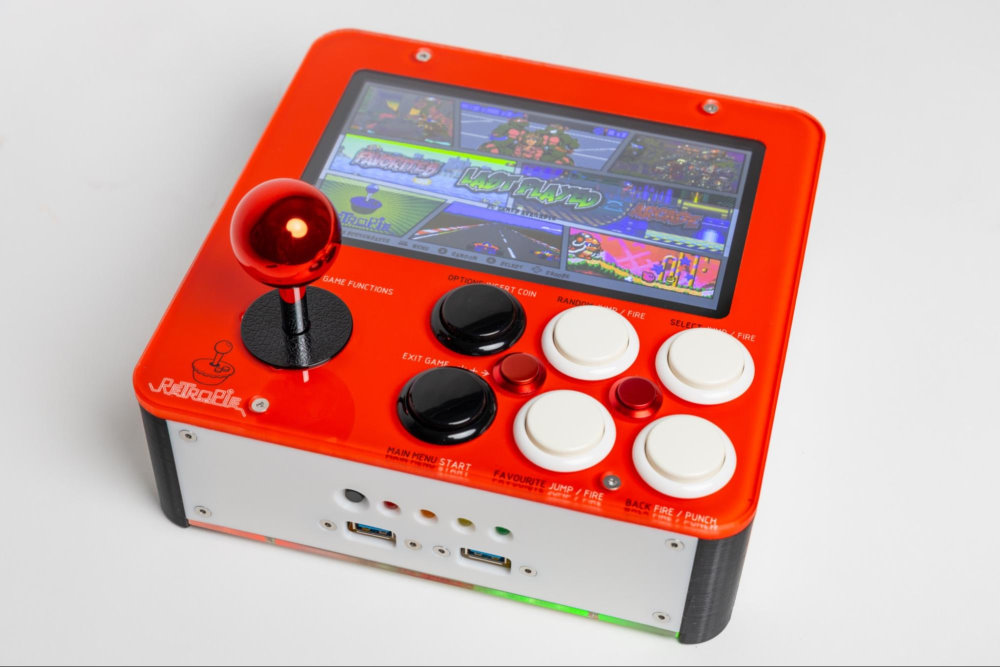
I am a Mechanical Engineer, and after 30 years in industry I now teach Engineering at High School. I create various projects in my spare time and bring them to school to inspire my students to try new things and not be afraid to experiment. I have always wanted an arcade emulator, but I was not keen on buying a ready-made device or copying an existing design, as I would have learned nothing. So I started this project in January 2020 and periodically made improvements over the next two years. I shared the evolution of the project with my students each time it was updated. Pictured here is Version 5 of my Arcade Emulator project, and probably the final version.
Description
As my first Raspberry Pi project there was much to learn and many challenges. The RetroPie software skilfully takes care of the emulation aspects of the project, so as a Builder Project, the primary task was selecting appropriate components and designing an enclosure to ensure the components would be securely mounted, yet fit closely together so the device could still be considered somewhat compact and portable by modern standards. The component arrangement also needed to result in a well-balanced device with functional control placement. The design was modelled in Fusion 360 and the Version 1 prototype was made of a modest timber box. The first two versions weren’t particularly compact, but they worked well as a starting point.
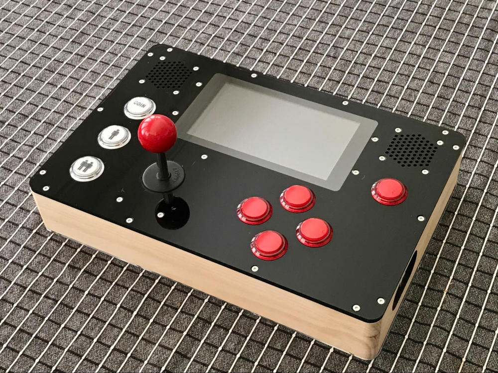

Early prototypes used microswitch-type arcade buttons, but they were found to be too noisy and far too bulky. The photos below are of Version 2, which required an external power source, but had the option to switch between the built-in display or an external HDMI monitor or TV. This design was too large and cumbersome, but the case now included many of the design features used in the final version.


After some 3D-printing mayhem while trying to print a one-piece case, I decided to design a modular case to enable flat-printing of the side panels, to optimise the outer surface quality and aperture shapes, and for the ease of future modifications or repairs. One of my Year 12 students accidentally dropped the Version 4 prototype, but the modular design made replacing the two damaged side panels easy. The screenshot shows the final Version 5 design modeled in Fusion 360.
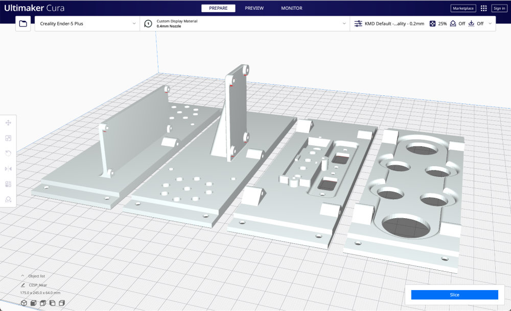
The screenshot below shows case components for Version 5 in the slicer for illustration purposes, but I actually only printed one part at a time so I could ensure the print quality of each part before moving on to the next. Note the outer case surfaces laying flat on the build plate, giving excellent surface quality. The Ultimaker Cura slicing software is awesome!
The case corner pieces were printed vertically to facilitate smooth curved surfaces without needing supports. Prototype case components were printed with 20% in-fill. For the final version, the case components were printed solid and without the need for supports or added print-plate adhesion. A Creality Ender 5 Plus printer was used with PLA and a standard 0.4mm nozzle. The bed temperature was 60 degrees and nozzle temperature was 210 degrees. Adhesion was achieved by scrubbing the glass build plate with a paper towel and methylated spirits immediately before starting the print.

The back-painted 6mm clear acrylic top and 3mm acrylic bottom were etched and cut using a 40W laser cutter after exporting DXF shape profiles to Adobe Illustrator. After adding the text and logo in Illustrator, the acrylic profiles were mirrored so the etched features were applied to the acrylic underside surface, giving a smooth and professional finish to the outer surface. Back-painting the etched button function text and RetroPie logo was done with a small brush while the protective paper mask was still attached. Once dry, the paper was removed and the rear surface sprayed with the base colour. The button function text is painted in two colours per button - one for RetroPie functions and another for in-game functions. A key appears above the joystick to explain this. The acrylic outer edges were smoothed and beveled with a trimming router before assembly.

The bottom acrylic cover features a rectangular array of 8mm ventilation holes for passive cooling, and this works fine even in summer, as long as the holes aren’t completely covered for prolonged periods. The casing corners extend 6mm below the bottom cover to facilitate cooling and also minimise scratches on the acrylic surface. The 3M double-sided tape (also used to mount the display) was used to affix the LiPo battery to the upper surface of the USB panel-mounted sockets.

A Raspberry Pi 7” touchscreen was chosen for its size, quality, ease of mounting to the Pi, and Pi video cable connection compatibility. As it is mounted under the acrylic top, the touch function is not used. The screen is mounted using 3M clear double-sided 6mm wide tape. The tape covers the full screen perimeter to act as a gasket to prevent dust getting between the screen and the acrylic.

A Python script and flush momentary buttons allow user control of screen brightness and volume, each of which default to 50% on startup. The volume and brightness buttons are mounted and coloured for intuitive +/- operation and are also accompanied by explanatory symbols embossed in the case.
A two pin header was added at SW1 of the PiJuice HAT to connect an external flush-mounted 25mm stainless momentary switch. A short press <750ms starts the device and a long long press >2,000ms activates a User Function that controls a soft shutdown sequence. A long press >10,000ms initiates a hard stop for rare instances when an incompatible game button configuration makes exiting the game impossible. The PiJuice HAT is also configured to perform a soft shutdown if the battery level drops to 5%.
#!/usr/bin python3.7
import os
from gpiozero import Button
from time import sleep
brightness = 50
os.system ('sudo sh -c "echo 50 > /sys/class/backlight/rpi_backlight/brightness"')
volume = 50
Vol = str(volume)
VolumeCommand = str ("'" + "Headphone" + "' " + Vol + "%")
os.system ('sudo amixer sset ' + VolumeCommand)
VolumeCommand = str ("'" + "Master" + "' 100%")
os.system ('sudo amixer sset ' + VolumeCommand)
BrightPlusButton = Button(5)
BrightMinusButton = Button(6)
VolumePlusButton = Button(24)
VolumeMinusButton = Button(23)
while True:
  if BrightMinusButton.is_pressed:
    if brightness != 0:
      brightness = brightness - 1
      value = str(brightness)
      print("Brightness: " + value)
      os.system ('sudo sh -c "echo "'+ value + '"> /sys/class/backlight/rpi_backlight/brightness"')
  if BrightPlusButton.is_pressed:
    if brightness != 100:
      brightness = brightness + 1
      value = str(brightness)
      print ("Brightness: " + value)
      os.system ('sudo sh -c "echo "'+ value + '"> /sys/class/backlight/rpi_backlight/brightness"')
  if VolumeMinusButton.is_pressed:
    if volume != 0:
      volume = volume - 2
      #print ("Volume:", volume)
      #sleep(0.1)
      Vol = str(volume)
      VolumeCommand = str ("sudo amixer sset " + "'" + "Headphone" + "' " + Vol + "%")
      os.system (VolumeCommand)
  if VolumePlusButton.is_pressed:
    if volume != 100:
      volume = volume + 2
      #print ("Volume:", volume)
      #sleep(0.1)
      Vol = str(volume)
      VolumeCommand = str ("sudo amixer sset " + "'" + "Headphone" + "' " + Vol + "%")
      os.system (VolumeCommand)
I love Arduino projects and coding, but I have absolutely no previous experience with Python - so the following script is not pretty, but it works. The script loads as the device boots and runs in the background by adding the following line to the rc.local file:
python3 /home/pi/LightAndSoundControl.py

An 8Gb Raspberry Pi 4 was used for the first prototype, but the final version uses a 1Gb Pi 4 with no difference in performance. A Class D 5W+5W stereo amplifier powers two edge-mounted 2” full-range speakers. Even at half volume these provide an abundance of clear sound. Two mounting screws for each speaker double as the external casing corner fasteners to save space. The PiJuice HAT with 6,000 mAh LiPo battery provides 3-4 hours of mobile operation.
In the final design, 30mm Sanwa silent arcade buttons were used. For the Sanwa buttons to clip into the 6mm acrylic top effectively, the rear edge of each button mounting hole was beveled 2mm with a router prior to painting. An 8-direction Sanwa joystick was installed after its steel mounting plate was removed. Sanwa hardware is still made in Japan and offers precise control with a solid quality feel - and at reasonable prices.
Wiring from the arcade buttons, joystick and zero-lag USB controller were made or shortened to correct length using Japan Solderless Terminals. DuPont crimped terminals made customising header sockets easy and neat.

External USB ports in the side panel nearest the user allow keyboard connection or an additional game controller. On the same panel, a momentary button activates a simple battery-level indicator, which contains a combination of rectifier and Schottky diodes. The red LED is illuminated whenever the battery voltage is sufficient to power a single LED. The orange, yellow and green LED’s progressively illuminate from 3.0VDC toward the full-charge voltage of 4.2VDC by utilising the diode forward voltages.
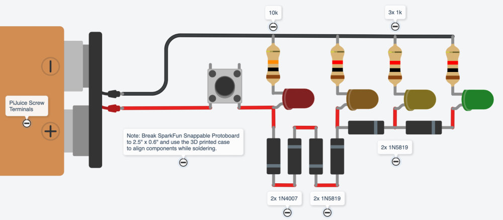
The Battery-Level Indicator circuit is constructed on a 2.5” x 0.6” section of Sparkfun Snappable Protoboard.
The approximate cost of the completed device is around $600 with a 1Gb Pi 4 installed, plus many hours of assembly and wiring. The device casing measures 208 x 208 x 70mm (plus joystick and button protrusions) and has a mass of 2.8kg.


Parts List
- Raspberry Pi 4 - 1 GB
- Raspberry Pi 7” Touchscreen Display
- PiJuice HAT
- PiJuice Battery
- USB C to USB A Panel Socket
- 64Gb Micro SD Card (eBay)
- Sanwa JLF-TP-8YT Joystick + Ball top
- Sanwa OBSF 30mm Silent Buttons x6
- Metal 16mm Flush Momentary Buttons x4 (AliExpress)
- Metal 16mm Raised Momentary Buttons x2 (AliExpress)
- Lanboo 25mm Stainless Momentary On/Off Switch (AliExpress)
- Zero Lag USB Joystick Controller with 2.8mm Connectors
- Class D 5W+5W Amplifier (AliExpress)
- Aiyima 2” Full-Range Speakers x2 (eBay)
- USB A Panel Socket Cables 30cm x2
- 3.5mm Stereo Straight / Right Angle Audio Cable 20cm (eBay)
- USB A to Micro USB 90-Degree Cable 20cm (eBay)
- USB C Round Panel Socket with USB A Jack (MicroUSB - MicroUSB Panel mount)
- 12mm SPST Momentary PCB Mount Tactile Switch
- Diodes (1N4007 x2 & 1N5819 x4)
- Resistors 1/4W (10k x1 & 1k x3)
- 5mm LED’s (Red, Orange, Yellow, Green)
- M3 Stainless Steel C/Sunk Socket Head Screws 10mm Long x24 (For case side joints, USB mounts and speakers)
- M3 Stainless Steel C/Sunk Socket Head Screws 12mm Long x8 (For acrylic top and joystick)
- M3 Stainless Dome Nuts x20 (For side panels and speakers)
- M3 Stainless Nyloc Nuts x2 (For corner in close proximity with Fire button)
- M3 Stainless Self-Tapping Screws 12mm long x6 (For 3mm acrylic bottom cover)
- M3 Stainless Self-Tapping Screws 6mm long x3 (For Battery-Level Indicator)
- M2.5 screws 6mm long x8 (For mounting Amplifier and USB Joystick Controller)
- Miscellaneous Wire, Paint, Crimps
Other Colour Variations
After successfully designing and building the Portable Arcade Emulator I made more colour variations:


- Raspberry Pi 4 - 1 GB
- Raspberry Pi 7” Touchscreen Display
- PiJuice HAT
- PiJuice Battery
- USB C to USB A Panel Socket
- 64Gb Micro SD Card (eBay)
- Sanwa JLF-TP-8YT Joystick + Ball top
- Sanwa OBSF 30mm Silent Buttons x6
- Metal 16mm Flush Momentary Buttons x4 (AliExpress)
- Metal 16mm Raised Momentary Buttons x2 (AliExpress)
- Lanboo 25mm Stainless Momentary On/Off Switch (AliExpress)
- Zero Lag USB Joystick Controller with 2.8mm Connectors
- Class D 5W+5W Amplifier (AliExpress)
- Aiyima 2” Full-Range Speakers x2 (eBay)
- USB A Panel Socket Cables 30cm x2
- 3.5mm Stereo Straight / Right Angle Audio Cable 20cm (eBay)
- USB A to Micro USB 90-Degree Cable 20cm (eBay)
- USB C Round Panel Socket with USB A Jack (MicroUSB - MicroUSB Panel mount)
- 12mm SPST Momentary PCB Mount Tactile Switch
- Diodes (1N4007 x2 & 1N5819 x4)
- Resistors 1/4W (10k x1 & 1k x3)
- 5mm LED’s (Red, Orange, Yellow, Green)
- M3 Stainless Steel C/Sunk Socket Head Screws 10mm Long x24 (For case side joints, USB mounts and speakers)
- M3 Stainless Steel C/Sunk Socket Head Screws 12mm Long x8 (For acrylic top and joystick)
- M3 Stainless Dome Nuts x20 (For side panels and speakers)
- M3 Stainless Nyloc Nuts x2 (For corner in close proximity with Fire button)
- M3 Stainless Self-Tapping Screws 12mm long x6 (For 3mm acrylic bottom cover)
- M3 Stainless Self-Tapping Screws 6mm long x3 (For Battery-Level Indicator)
- M2.5 screws 6mm long x8 (For mounting Amplifier and USB Joystick Controller)
- Miscellaneous Wire, Paint, Crimps

