This project came about for a number of reasons. Firstly, we wanted a real showpiece for the school's Resource Centre. It's a real talking point and when people find out that it was made almost entirely by students they are always impressed. Secondly, STEM and Digital Technologies are areas we are really trying to grow and promote so this project was perfect.
The following project is a rundown on how students and teachers created an arcade machine for playing MakeCode Arcade games running on a Raspberry Pi Zero.
Equipment used
- Raspberry Pi Zero with male headers
- An SD card
- Micro USB to USB A cable
- Mini HDMI to HDMI adaptor
- HDMI to VGA adaptor
- Computer monitor
- 4 x arcade buttons
- 1 x arcade joystick
- Spade connectors (optional)
- Copper cable (red and black)
- Female jumper cables
- Speakers
- Wood panels for cabinet
- Castor wheels
We followed Microsoft’s ‘cardboard’ guide which takes you through all of the technical instructions for creating your own arcade-style controller.
Step 0 (optional)
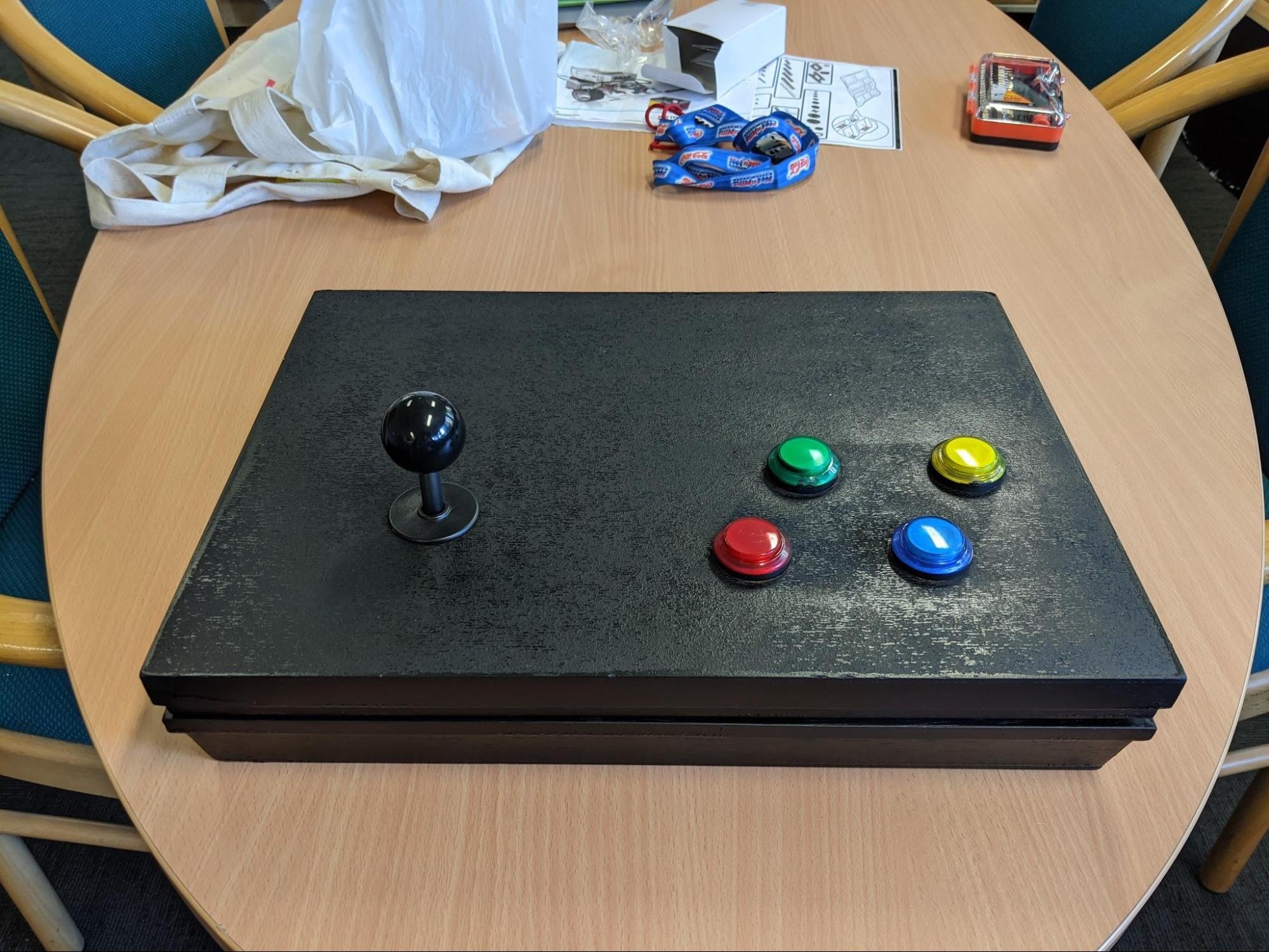
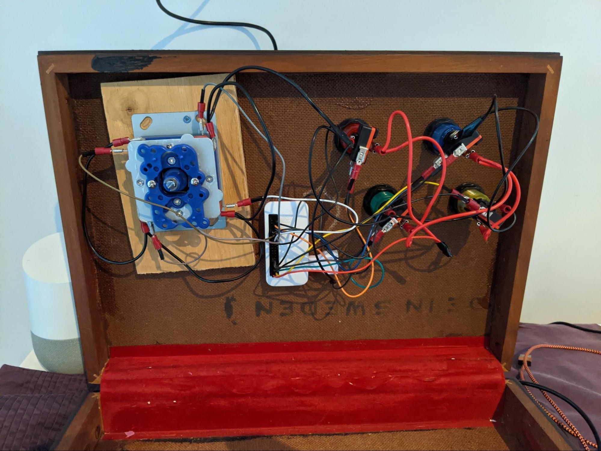
The very first step was to build a prototype machine to confirm it would work and make mistakes / learn lessons from the process to ensure the real build would be a smooth one. All of the components were the same just assembled in an old slides box.
 |
 |
Step 1 - Cabinet construction
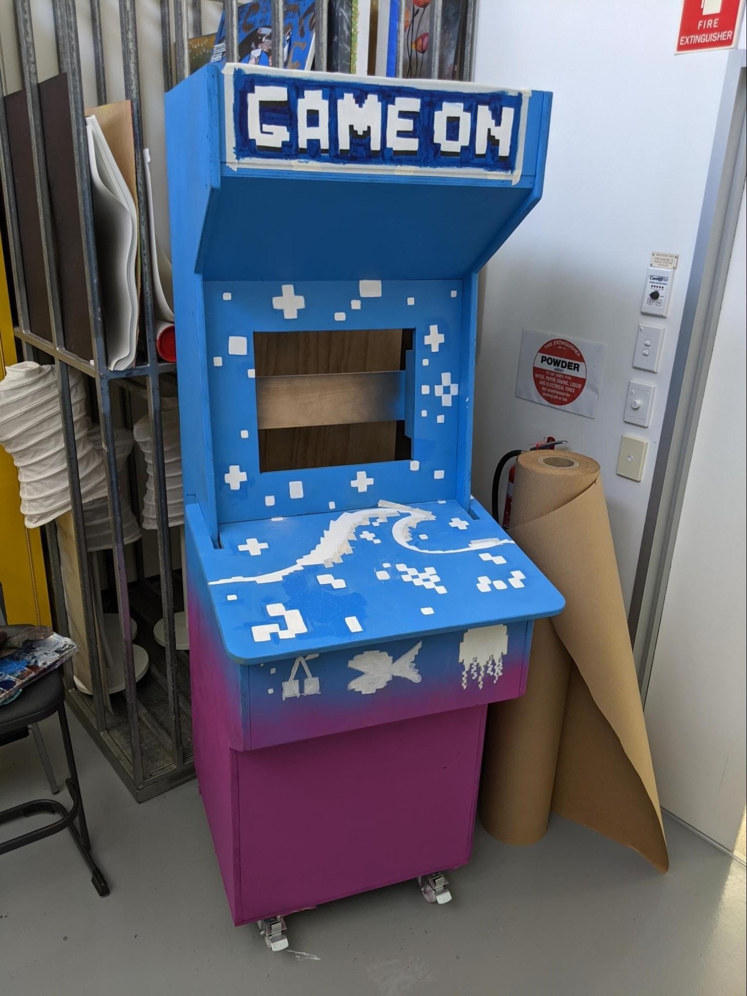
Our manual arts teachers constructed the cabinet based on designs found on the internet. We configured it to fit a Dell VGA computer monitor we sourced to use as the screen. The panel where the controls go slides into the cabinet so it could be easily opened to access the wiring and components inside and is secured with two screws. Finally, the cabinet was fitted with castors so that it could be easily moved between faculties at school.
Step 2 - Painting
Art students were tasked with painting the cabinet so that it looked the part. They were given a design brief to incorporate school colours and a retro game aesthetic.
Step 3 - Fitting the hardware
5 holes need to be drilled in the top of the cabinet to mount the buttons and joystick ensuring there is enough of a margin between each other and the walls of the cabinet to fit the wiring.
We removed the stand from the monitor and mounted it to the cabinet ensuring there is room to fit the power and VGA cables.
We chose to mount the speakers inside the cabinet at the top to keep it clean and drilled holes near the speaker to let the sound pass through. You can also see how the back of the monitor is mounted in the image below.
Step 4 - Wiring
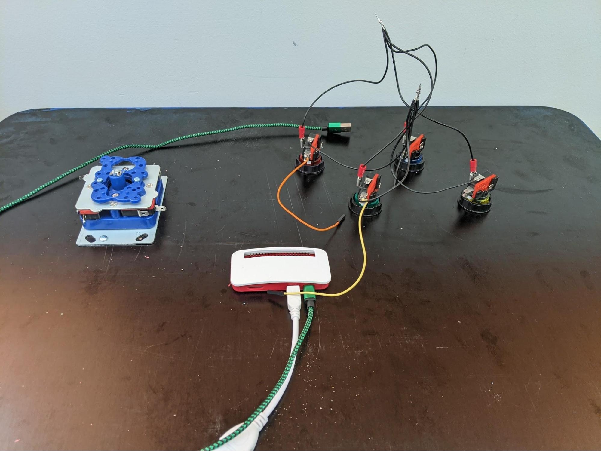
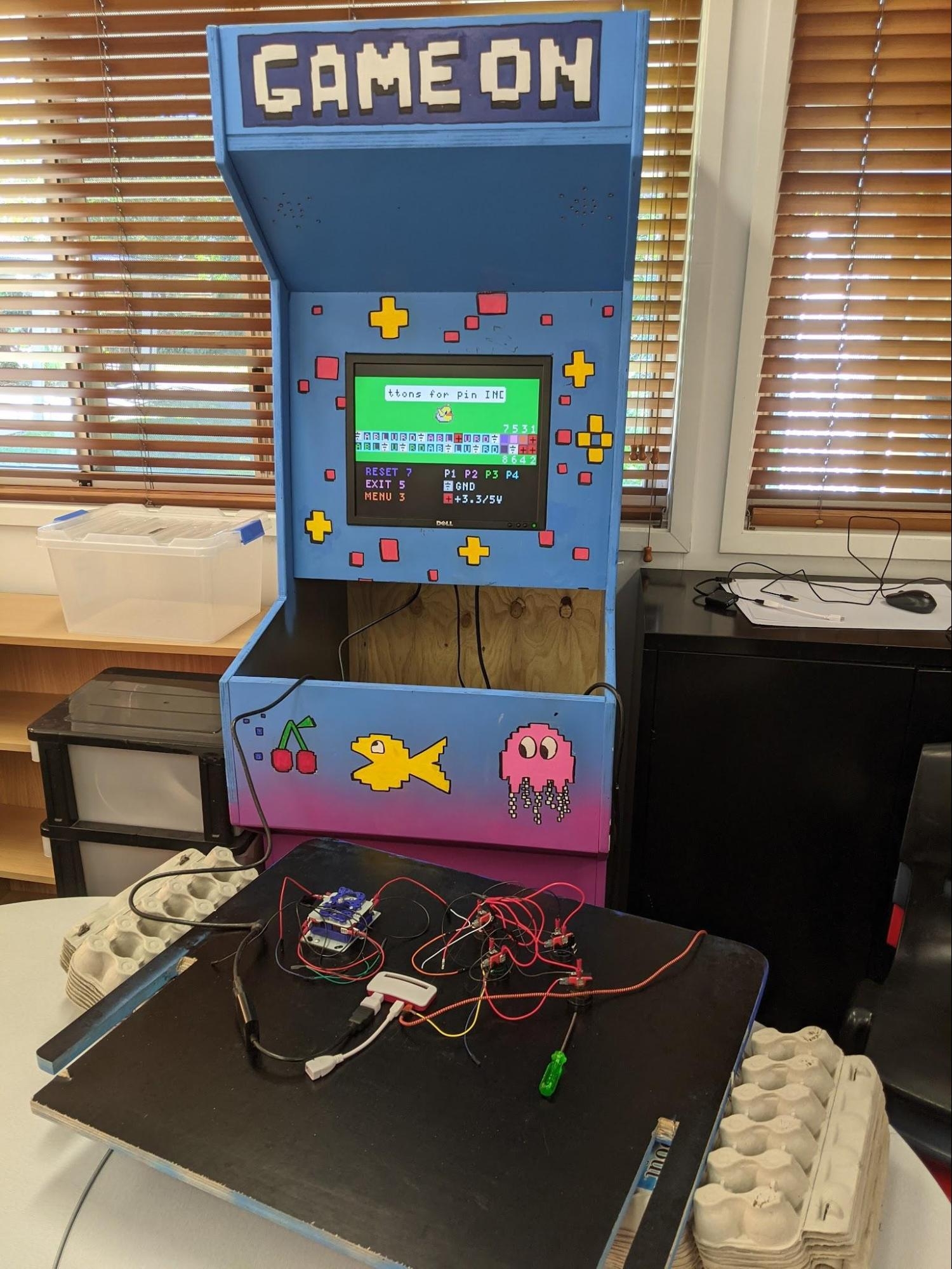
Wiring the buttons and joystick to the Pi Zero is the most tedious part of the process. The buttons we chose are the kind that light up so require power and hence more wires. The power and ground for the lights are daisy chained to each other then connected to a female jumper cable that connects to the Pi. We used a combination of spade connectors and soldering directly to the button connectors. The Pi is screwed onto the cabinet and I ended up removing the case as it was just getting in the way. If you do remove the case you will need some spacers underneath the Pi as it will be too flat to fit the USB and video cables otherwise. The last step is to install the MakeCode files on the SD card and run the configuration program to setup the buttons.
 |
 |
Step 5 - Making and playing arcade games
We ran a competition to create games for the arcade machine using MakeCode Arcade. All students who contributed to the project got to sign their name on the back of the cabinet. The Raspberry Pi Zero is a little underpowered for some of the games students make but otherwise it is rock solid. The sound is not loud enough with the passive speakers we used so we will need to get an amplifier at some stage.
- Hunt down some ghosts in Pacman’s revenge - https://arcade.makecode.com/23705-98994-57256-48439
- Back to the classics with; Asteroids - https://arcade.makecode.com/18078-40607-73980-71163
- Spam the buttons on Chicken Run - https://arcade.makecode.com/54923-72107-75221-61550
Where to next
The next project is going to be a sustainable power supply to run the machine - a spin cycle hooked up to a bank of batteries. The plan is to gather and display the data from this generator (distance ridden, power generated, current charge level, the time elapsed, etc).


