It is real and here it is! Including everything you need to make one a Luma 1 for yourself! So allow me to introduce you properly to the Luminator Mark 1. I'm talking all the ins and outs of this inside-out neo disco ball so you can be ready with extra oomph for your next party.
Quickly I'll run through some specs. It is totally sound-reactive, controlled by a Raspberry Pi, and has a depth that tears through space from twelve two-way mirrors.
This cut-out dodecahedron has endless light control as each of the 180 LED nodes are fully addressable and are controlled by totally customisable Python code. If you want to learn how to jump into programming come check out my Python Workshop.
3D printing, soldering, programming, micro-processors, LEDs and two-way mirrors were all combined together to make this project a reality. This idea came into fruition because of the current lack of parties and festivals (in particular the amazing light displays that big music crush) and a longing to bring the lights of the big stages to home. I hope it gets you as psyched as it does me.
Also conveniently Luma just so happens to mean light in Latin.
 So here is the process I took to make the Luma 1.
The overall feeling of this build was all about not having enough materials, waiting for more material to arrive and lots of test-fitting/tear-downs to get it all just right. Most projects are like this but pulling them off in the midst of the end of the world involved a significant amount of patience waiting for parts. Also as the project developed as time passed as I became more ambitious about including certain features. Shout out to Ludacris for getting me through the final build up.
The contents of the Luma 1 project can be seen below.
- Parts Required
- Tools Used
- Project Build
- Acknowledgement
- Where To Now
If you want to build a Luma yourself or want to ask questions we are always available to answer questions and queries. Also, if you have ideas to add please let us know your thoughts!
Parts Required
There were a number of times that this project developed in a certain way and then was backtracked to go a different route. Thus the part list below is those used on the final design.
- Individually Addressable LEDs - WS2812B LED Strip 60 LEDS Per Metre, 5 Metres with Black PCB.
- 3 Pin Extension Wire Cable Connector for WS2812B LED Strips.
- 60 Wire to Strip Hippo Clips 3 Pin. Definitely good to have a couple of spare.
- JST-SM Pigtail Connectors
- DC Power Connector
- Jumper Wires
- 3D Printed PLA Dodecahedron External Frame. Do not have a 3D printer? No worries we offer an in-house printing service right here at Core Electronics. The STL file is attached at the bottom of page.
- 12 Sheets of Two-Way Acrylic Mirror 2mm Thick. These are then cut into a pentagon shape. This is a product you can buy in squares if you scout for it. Also Core Electronics offer an acrylic laser cutting service. Then you can use Mirror Tinted Window Film to make the petagon two-way mirrors.
- Vellum Paper. Tracing Paper will give a good diffusion result.
- Raspberry Pi 4 Model B. Having peripherals makes the programming aspect of this project much easier. Found here is everything you need except for a monitor.
- 5 Volt DC 10 Amp Power Supply. This provides the power for the LEDs
- Raspberry Pi 4 Power Supply USB C
- Micro SD Card for the Raspberry Pi
- USB Powered Mic
- Solder
- Primer and Black Spray Paint
Tools Used

Below is a list of the tools I utilised to make this project a reality.
- Pliers
- Soldering Iron
- Soldering Helping Hands
- Drill
- Box Cutter
- Metal Ruler
- Super Glue
- CAD and Slicer Software
- 3D Printer
- Vernier Calipers
- Sandpaper
Project Build
Below will be each step by step of the build process I went through to create the Luminator Mark 1. Starting from the conception of the idea, to the CAD work and all the way through the physical construction. I will also elaborate the moments in the project that did not go to plan and how I problem solved past them. This was a fun build and I hope by methodically going through the process you will be inspired to go out and make one yourself. The more Luma's the better!
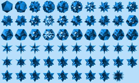
1. Shape choice. I had this idea of creating an intricate shape, hollowing it out, encasing it in two-way mirrors and filling inside with LEDs. I had seen an art sculpture which had created this amazing effect using a similar idea which spurred me on. So the first step was picking a 3D shape. It had to fill two criteria, I had to like it and it had to create swell internal light bouncing effects. All the shapes referred to in the follow can be seen below. So, I dabbled with the idea of an icosahedron and decahedron. Considered some stellations of the icosahedron I always really jived with. Pondered on stackable shapes as well. Doing that would make the internal mirror effect appear to take you to a world of stacked tessellated shapes. Stumbled into the partial stellated rhombic dodecahedral honeycomb. That with internal mirrors would be unbelievably cool. Also, dabbled on the rhombicosidodecahedron which is the polygon most soccer balls are. Then I fell into a world of small stellated truncated dodecahedrons and the chad compound of twelve pentagrammic prisms but at that point I had to stand up and take a step back.

After some tea I locked onto the dodecahedrons. It would offer an excellent wide windows into the mirror world, had nice complexities but the same face shape, was non-stackable so the patterns would look more random and most importantly I overall received a swell vibe from this shape.

2. Is now time for some CAD (computer aided design) for the external frame. The goal was to create a dodecahedron which is hollow inside, has only has edges and was big. At this stage I also figured I would need some space for electronics to seat internally along the edges. The design was made symmetrical so it could scale easily. The limiting factor in regards to size came down to the two-way acrylic mirror filling it. The other limiting factor I considered at the time was the print bed size but that stopped being a factor when I decided to print it in sections.
Now a quick rundown on the process I went through to make the external frame design. There are several ways to go about making a dodecahedron in CAD and you can even find STL generators for them online. The process I went through can be seen below in the image starting with a 2D pentagon sketch. This pentagon was then extruded up with a taper angle. Then on top of the extrusion and directly above the previous pentagon I created another 2D pentagon, same dimensions as before but flipped. The are outside the pentagon was then used to extrude cut, with the same taper angle used before, downwards. This removes all the excess and leaves you with a perfect dodecahedron. I created another one slightly smaller using the same technique. This was then located to the centre of the other one. Then utilising Cut Intersecting Bodies tool the inside smaller shape hollowed out the outside shape. I then created pentagon holes on each face to create windows to peer into.

3. Figuring ways to 3D print the external frame. I would need to get inside the Luma to tinker with it so original plan was to print it in two sections. This idea can be seen in the image below left. This would require a very dialed in 3D printer and a really large print platform. This large print platform is demonstrated in image below right where the external frame is completely encasing the Ultimaker S5 print bed. Also a wire frame image of the final design can be seen in below centre.

4. 3D printing the external frame. A first an attempt was made to print the base as a single piece. This was quickly scrapped as it would be a massive print however the off-piece from the attempt was very useful as a guide throughout the project. The focus was turned then to 3D printing edges and corners. Then assembly of them would happen after the print. Dodecahedrons have 12 faces made up of 30 edges and 20 vertices. So, 30 edges and 20 corner pieces were printed. Multiple edges and corners were printed during a single print to speed up the process. These were all printed in PLA on a FDM printer with a large print bed and smoothie-board as the brainbox.

5. Cutting the two-way mirrors. At this stage the Two-Way Mirrors appeared at my door after a long wait. They all needed to be cut into the pentagon shape to fit into the external frame. I ordered twelve pieces and, as dodecahedron have twelve edges, failure was not allowed. I had waited a long time to get them into my hands, I definitely did not want to wait again. A large metal ruler and box cutter is what I came up with to cut the shape. The twelve sheets I ordered came were rectangular with removable plastic sheets on both sides to protect and indicate the mirror side. With two way mirrors there is always a mirror side and a look through side.
I took my time measuring out the first window. Also always wear gloves and be safe when using sharp tools! When it came to cutting I would do multiple passes over the same cut so as to not shatter the glass-esque material. Cutting was done with a sharp box cutter and a metal ruler as a guide. Then that metal ruler would be used to snap the material along the cut mark when the time felt right. Once the first window was made, and I double checked it fit using the off-cut 3D print, I used it as a template for the other. Some freedom was enabled as I had a lip on the 3D print so the edges did not need to be perfectly cut as it would not be seen. The mirror material I used was not happy about being sanded or cut in certain directions. Also it was easy to scratch so big care was taken to keep them nice.

6. Gluing the 3D printed parts together. First each 3D printed parts of the external frame was cleaned. Then each corner was superglued to an edge and after a while the dodecahedron form started to appear. To make adhesion between each 3D printed part stronger scratches and marks were done to the connecting parts before gluing. Now as tempting as it was I did not glue it all together. I decided instead to create a lid with the top face. This lid was made up of 5 corners and 4 edge pieces. This lid then interlocks with the lower part of the dodecahedron via dowel bits. I drilled out the frame with holes to accommodate this and as they all slightly face inwards they create a very sturdy connection.

7. Finishing the External Frame. Once the Frame and lid was complete and glued time was spent making the final finish darker and smoother by sanding, priming and spray painting. This hid the connecting lines and in a dark room makes the borders look invisible compared to the mayhem inside the orb.

8. Light controlling plans. No solid plans at this stage on how exactly I was going to light this guy so schemes commenced. I knew from the get go that I wanted to control each light node independently and that it had to be bright and fast. So fully addressable LEDs were the natural choice for this. From there I decided I would control them either by an Arduino or Raspberry Pi. A Raspberry Pi is what I settled on as I really liked being able to code to it directly through the operating system. The advantage of controlling the lights this way is that there is complete control of each node of light. It also meant I could break all the lights by sending through too much energy, so care was taken. Later on in the project the idea of making it sound reactive was too hard to resist to an External mic was added to the electronics.

9. Wiring the External Frame. I practised and thought about different ways of wiring up and laying the internal loom. Loom is what I will now refer to all the LEDs and wires inside the dodecahedron. Quickly I realised it was impossible to connect each corner of a dodecahedron with an unbroken non-overlapping line so some lines would need to overlap. I decided on running a loop around the bottom edges then going up a layer edge going around the centre edges of the dodecahedron looping back to the centre when needed then finishing the top as a single loop. Below to the left shows me testing around ideas with string. Below to the right show the final loom choice I went with. The star indicates the starting point and end point. Green is the top and bottom loops. The blue and pink are the middle section where some wires overlap the LEDs.

10. Quick Drill. I drilled out a small hole in a bottom corner of the dodecahedron to enable wires to get out. I took sometime after doing this to figure out how I will go about powering the loom. Below shows the final design with the cords coming out of the drilled hole.

11. Getting juice. Looking online I could see that if you did not have enough power supply you would end up with less bright LED at the end of the strip. Cannot have that! The LEDs I bought used 5 volts so that was locked in and the max amps you can draw from the wall in Australia with this voltage is 10 amps. So I found myself a big power supply online that gives 10 amps and had that shipped to my door. The details about it can be seen in the image below.

12. Increase the LED density. The LED I initially used didn’t have the density I desired with only 30 pixels over the 1 metre. I still had a go making the loom, good practise and all that. So I soldered together the lowest loop. That lowest level made for 30 soldered joints. At this point it was some 4 nodes per edge which was not enough. Soldering in this manner was also very arduous and finicky. It left very little room for error in the wire cutting and each wire had to be stripped. Once an edge section was complete it was zip-tied in place to the inside of the dodecahedron. After getting about a third through the entire loom I put some power in. As it didn't work perfectly I started troubleshooting each connection point. It was right at this point I pulled the plug and stopped. I was not happy with what would be the end result going down this path. This unfinished initial loom did serve as a useful component later on to test out the reactive code so that was swell. Below is an image of this incomplete loom with a zoom in of the way I was connecting each segment together.

13. Tea and research time. Research time introduced me to Hippo Clips. Bought a batch thinking that would be heaps, waited some time, got it, realised I would need a lot more, bought a big batch, waited some more and finally had a bag of all these swell connecting pieces in my hands. During this time I also received much more dense LEDs so I could fit more nodes into each edge. This meant I could fit 180 LEDs inside my cube, 6 nodes for each edge section. I could have gone even denser however I would have required another powerpack to get more amps into the system. Luminator Mark 2 is on the horizon so we will get there. See below some images of these hippo clips in action.

14. Work started on Loom 2. Hippo Clips are better than soldering LEDs. Fact. However, they are not a perfect connection and two are needed to connect one strip to another. That means in the end there was almost 60 of them needed in the cube. Over a night a large amount of energy drink and dubstep was consumed and finally the loom was complete. No mirrors were installed but every edge had a section of led strip seated happily in it with a two zip ties holding each strip in its section. The zip ties are particularly important for the ones in overhanging sections and testing the fit. Check below for images of the first full test fit.

15. Quick Tips on using Hippo Clips. Testing fitting was done to make sure the wire lengths were good. This was the method I used to get the best connection with hippo clips. If I had done this at the beginning it would have saved a lot of troubleshooting later on. Use a pair of plyers to properly crush the connection together. Make sure the wires are lined up correctly over the puncture point. If the electronic juice is not flowing correctly crush the whole clip with plyer hard and then make sure the side tabs of the Hippo clip are pressed together. These can be temperamental and if you run into a particularly upset one just chuck it out and grab another.

16. Powering the LEDs and Raspberry Pi. All the power for the raspberry pi was done through USB C. The power for the LEDs were done through the extra power wire that the LEDs possess, through a DC power connector barrel plug. This barrel plug also has ground wire for the LEDs. To tell the LEDs what to do PIN 12 was used and PIN 16 was used as ground. Note the swell case for the Raspberry Pi, find out more at this location. All the connecting that was ever done in this project can be seen below.

17. Power and troubleshooting. Almost each hippo clip ended up needing a little extra squish with the plyers or a wire rearrangement to make it a good connection. I powered the system, turning the LEDs and worked methodically through the loom. Make sure to turn off the electricity when working with the wires! There was two LED nodes that were broken on two separate strips so the strip was removed and replaced with another. You can tell a node is not doing the right thing as the light will flicker on and off or lock itself to a bright colour. They broke likely due to the over zealous bear hands and not a manufacturers fault. Once this was done the whole loom was operating really well. During this process all excess wire was cut down and if the angle was not quite right I would redo the connection to get the angle just right. The LED strips had a habit of lifting up and off the edge if there was too much wire between the hippo connectors and the goal was to make it flush. See below for the loom lighting up at the end of the troubleshooting session.

18. Thoughtful tea time number two. Now it was time to figure out how to get the mirrors to stay with the loom on the external frame. I really wanted to avoid using adhesives for this and was pondering how to go about this for a while. One morning it hit me, drill holes through the mirrors and then zip tie all the mirrors and loom to the dodecahedron. This meant I could easy pull it all apart to fix and troubleshoot. To do this cleanly two zip ties would be placed on all the edges which would thread through two mirrors and the loom. Then it would tighten to the dodecahedron edges.

19. Drill time. Holes which perfectly fitted the zip ties were then cut into the mirrors. This was done with a very sharp drill bit and a high speed so that the mirrors would not shatter. A lot of care was taken to prevent unwanted bending or scratching during this process. None of the pieces were allowed to break so care was really taken. The holes were marked out using the initial 3D printed piece and two were drilled for on each mirror edge. Twelve panels and roughly ten holes per panel made for almost a hundred and twenty holes.

20. Cutting Vellum to hide the wiring. The end result I desire is for nothing except mirror and light to be visible inside the cube. With the design for Luma 1 I decided to use vellum paper. This would hide the LEDs and wires whilst majorly improving the light diffusion. Check out the Huge LED Pixel Matrix Sam made which also utilised vellum paper. Absolute chad. Vellum also makes the Luma 1 less of a migraine inducer (at least once it was made jks) and seems to add further depth to the final end effect. The vellum paper was cut on a chopping board with a metal ruler and box cutter seen in the image below. The final dimension of the vellum paper were determined through trial and error.

21. Threading the needle. Thus, each zip tie would also need to thread through two holes of a bookmark shaped slip of vellum paper along with everything else. For Luminator Mark 1 I am happy with the result, but I have schemes to make the inside of the dodecahedron even cleaner in the next version. Below shows the vellum paper hiding the wiring and LED below, just ignore the reflection of the table.

22. Starting the final build up. So with all the pieces ready and multiple loom and mirror test fits the final build started, from the base up methodically placing the loom, 2 way mirrors and velum. Testing was also done at various points to ensure the Hippo clips were performing the job they were created to do.

23. Finishing the Top. Once reaching the lid I pondered over the best way to connect it to the system whilst making it easy to pop off so I could get my bear mitts into the depths of the dodecahedron. I could not just zip tie the lid as I would not be able to open it. If I zip tie only the lid mirror then the zip tie would push against the lower mirror and not let me close it flush. A major compromise was made and I used some adhesives. Clear wrapping up tape that you use wrapping up presents to be straight. This allowed me to line the top with the loom all angled correctly whilst making it easy for me to remove the top. A long tail of wire is between the top and bottom of the dodecahedron for the same purpose. A big part of me wants to go back, redesign and 3D print a solution. Doing so would also increase the longevity. And with that I closed up the system and powered it up. Excuse the poor footage but below you can see it running properly for the first time and a little peak into the other realm it creates.

24. Code time. Work was done on the Python code that on the Raspberry Pi. This and installing Python Packages was done. I accessed the Raspberry Pi directly to start off with then remotely through WIFI using an application called Putty. This is referred to as headless access. Schemes of controlling this through a phone app are firmly on the table. I connected a USB Mic to the Raspberry Pi and sorted different sound-reactive modes based on both loudness and real-time sound spectrum. If the room is really loud or really quiet then the code accommodates for this so that there is always a variation of brightness and colours. These can be jumped between on command. Plans to increase the complexity and variety of reactive modes are also firmly on the table. The reactiveness really brings life to the Luma 1. Also a tip for other budding makers, if you are going to make a project it is always a good idea to make one that encourages people to clap at it. Seen below is screen caps of some of the code running in Raspbian OS, the native operating system of Raspberry Pi. Also below is the USB mic used and it connected to the Raspberry Pi.

25. And with that the build was finished! See image below of some of its features.

Acknowledgement
As Isaac Newton said 'If I have seen further it is by standing on the shoulders of Giants'. Big shout out to the support I have from everyone around me. Another big shout out goes to Nazmus Nasir for giving me direction with the Python reactive codes. Go check out his awesome Youtube for other great projects.
Where To Now
Next step is creating one twelve foot high which I can bathe in it and creating another one for DJ headwear so that the dodecahedron encases the DJs head. Also I have yet to take it to a party so that will have to happen too. Come check out the video above to see it properly in action!
Big shout out to Adam Savage for putting the fear of god in me with his one-day Rhombic build. Really put a fire underneath me to get this built.
