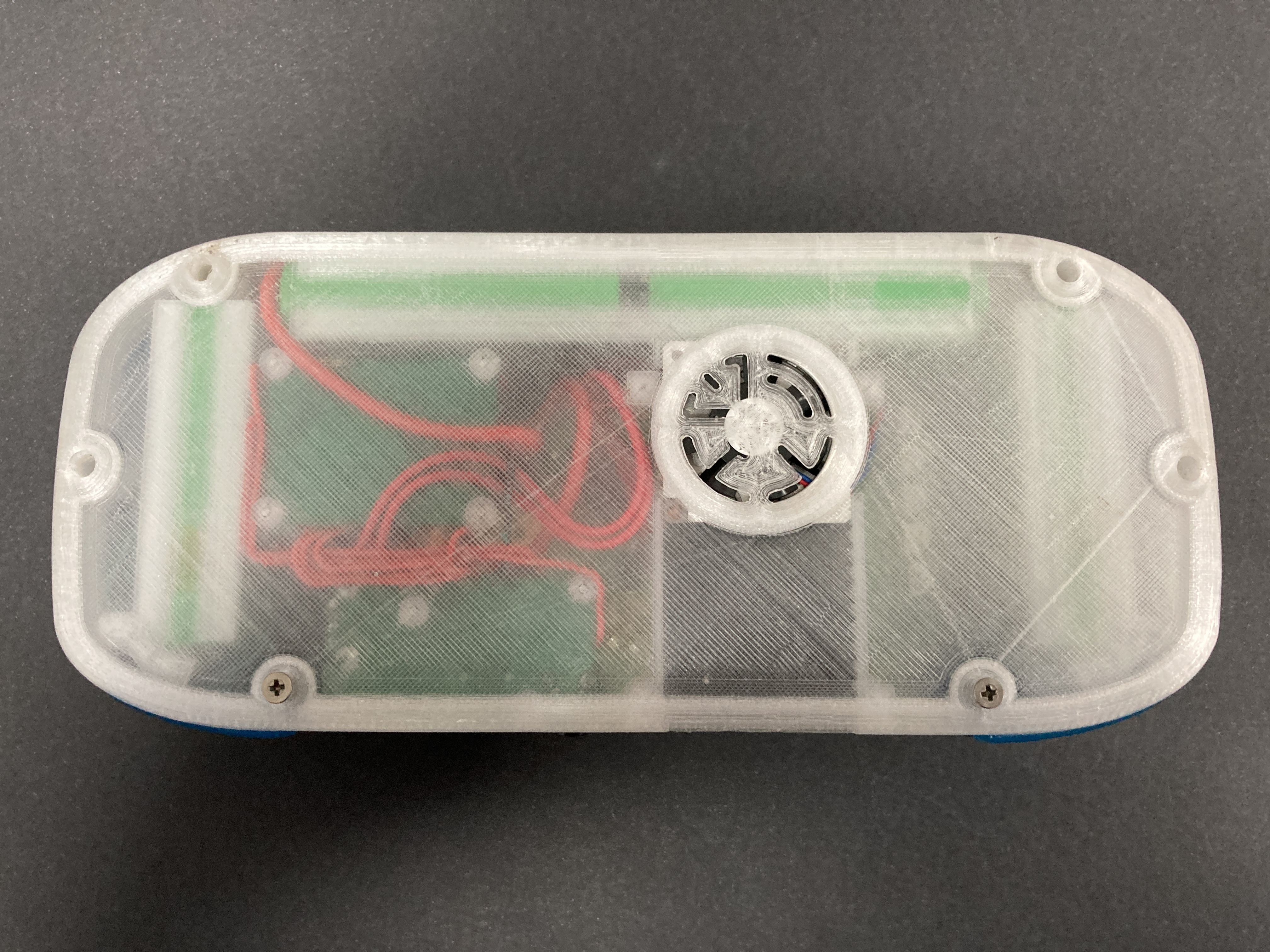
Do you love your Wii and its ability to play all GameCube games perfectly but wish you could take it on the go like a Gameboy?
Well, I definitely did and if you're like me so do you. And here is the right place to learn how. There has never been a better time to get into the Wii Portabilising (S-Tier) or any console portabilising in general. The wealth of well-documented knowledge online, incredible free software, cutting-edge circuit boards, and the most helpful community are just some of the reasons why.
Personally, I love GameCube games and find I only get time to game nowadays when I am traveling from place to place. So to rectify this problem I knew I had to create a device that would let me play my GameCube games perfectly. Emulation, not only being a bad and nefarious action (disclaimer - truthfully emulation is a good thing saving many great games from the sands of time), never reaches the peak of playing on native hardware.
So when you look deep enough into a Wii you will eventually come to the realisation that really it is a supercharged GameCube with a whole bunch of Wii Remote Sensor capability attached on the side. From there I discovered the huge online community revolving around portabilising devices. Wii’s also have not quite reached their nostalgic price-gouging stage in their lifespan so you can still get them for dirt cheap. The one I am using here cost me $15 Australian dollars second-hand.
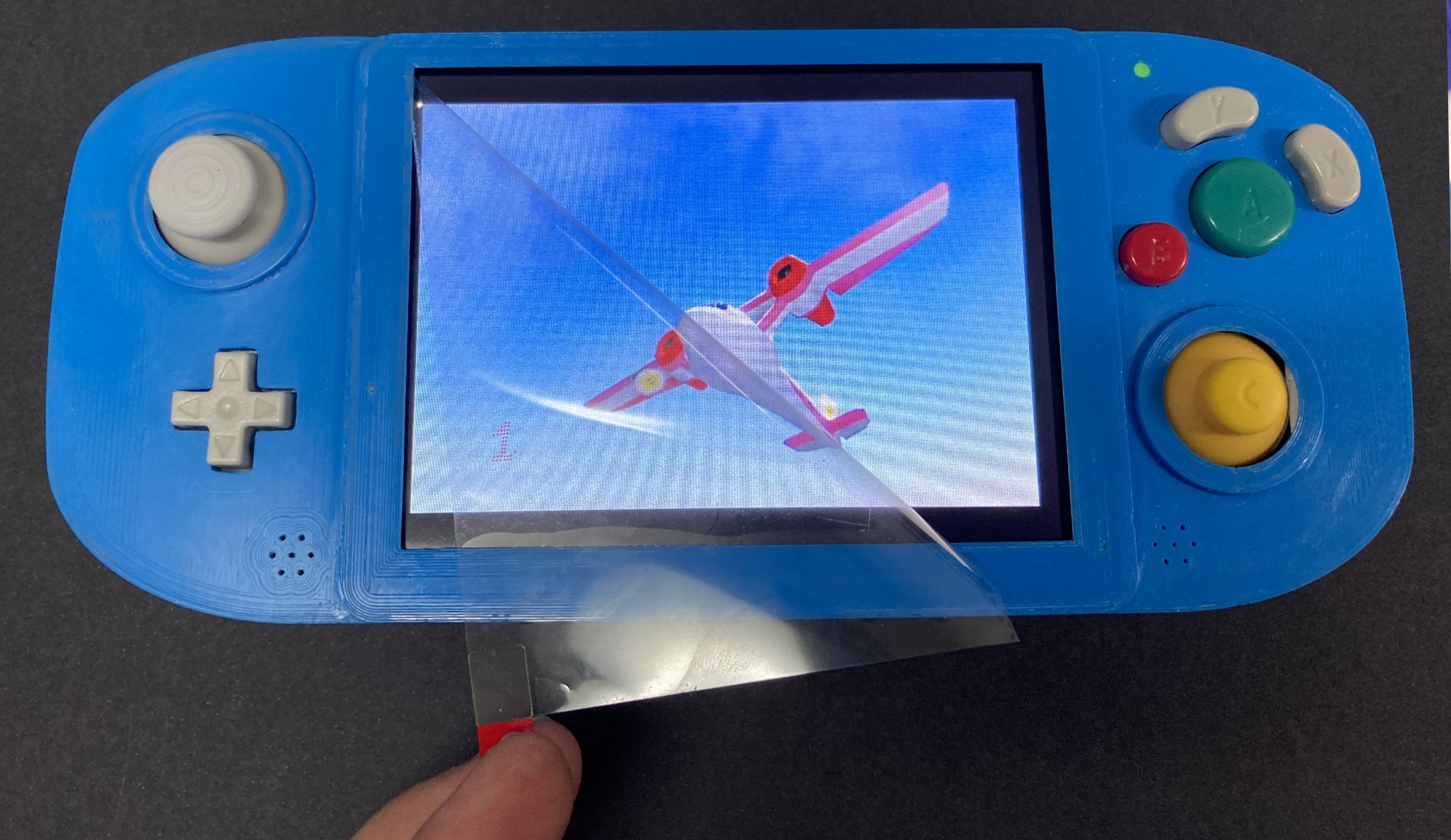
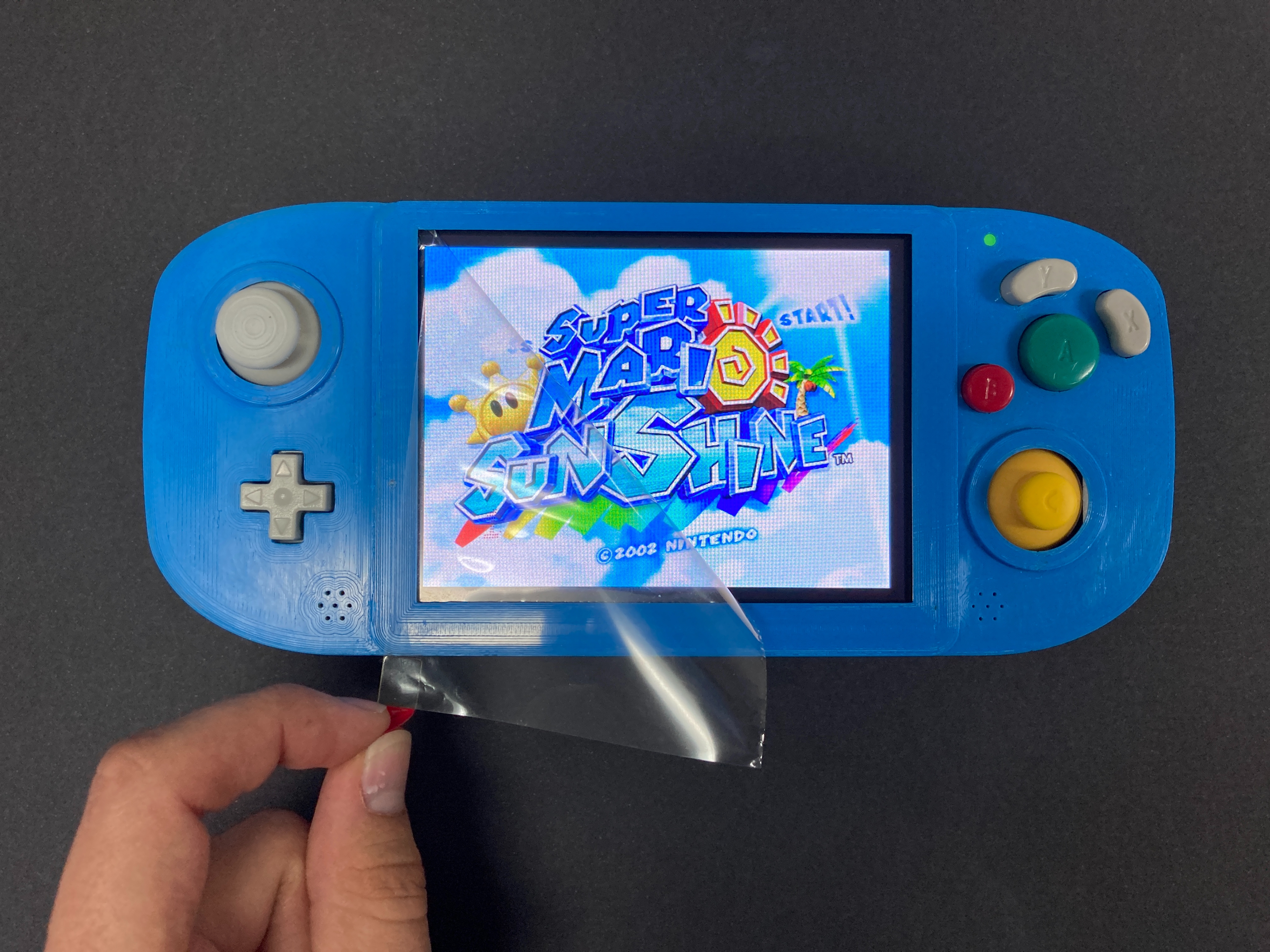
So from there I was hooked and embarked on my G-Wii Journey. Below is an image of Super Mario Sunshine playing on the G-Wii.
So I got my Ben Heck Portabilising Hat on and cracked on in. So let's rip apart a $15 Wii that we've filled with extra software and then take a diamond cutter to the motherboard until we are left with just a tiny fragment. Then we will bring that fragment back to life using the most advanced life-support circuitry I can get my hands on. Provide it a beating heart by soldering directly (and extremely carefully) to 18650s and from them create a battery that will last 4+ hours. Then we will pull apart a Gamecube controller and use the buttons from it to maximise nostalgic and ergonomic happiness.
Overall, this makes for a beautiful trifecta of 3D Printing, Software, and Electronics.
Project Description
The goal is to make a Wii a handheld device with at least 4 hours of battery power.
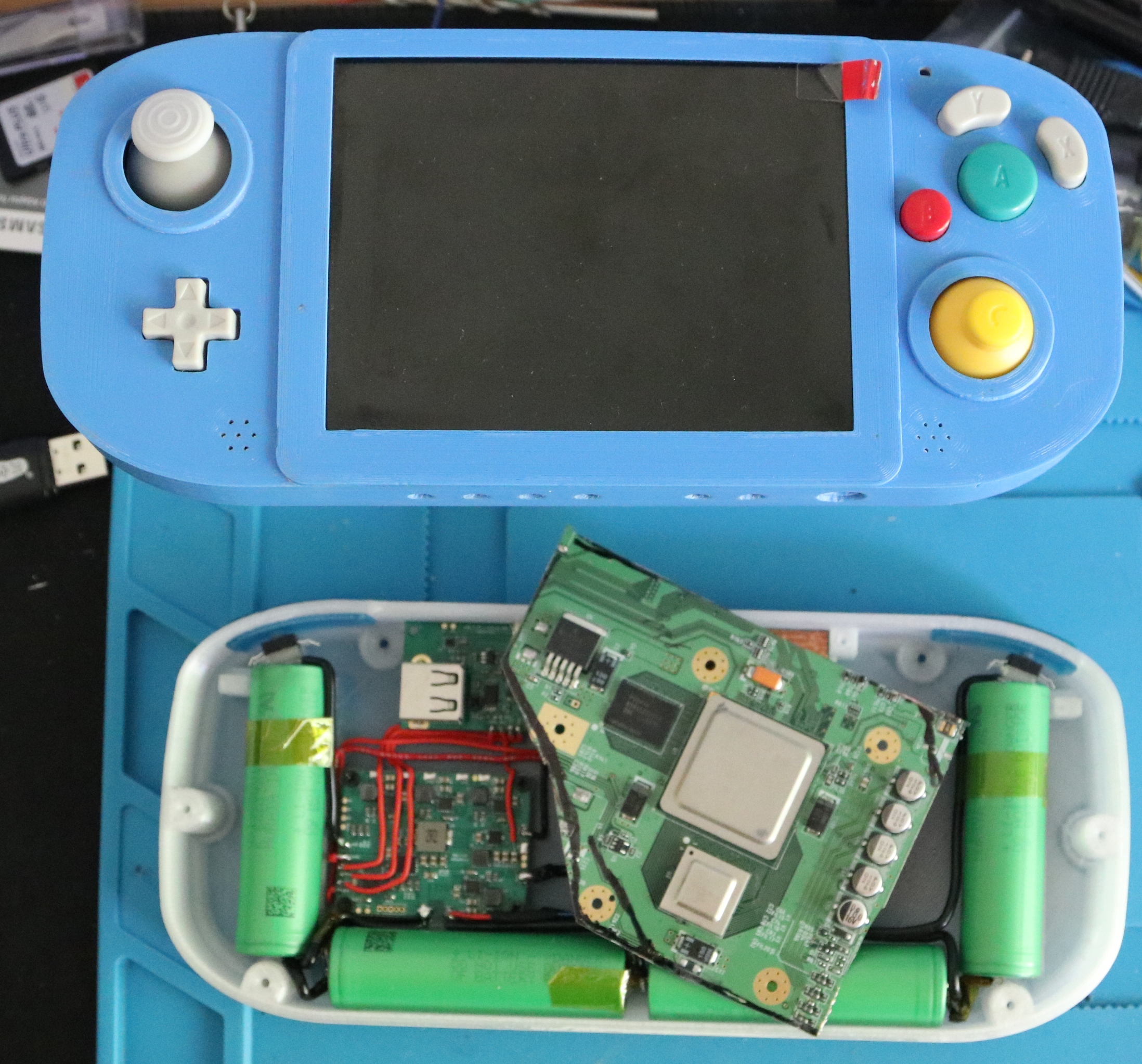
This takes some serious soldering. Recently I found myself doing a whole bunch of solderless projects but I do not want the world to think that soldering is something that should be avoided, it is just a unique skillset that takes time to get right. Being confident in soldering only takes practice, is a skill that you will never forget, and will open up doors to prototyping and hacking that you could never reach otherwise. So here is the process I went through to create this portable Wii. Shout out to Kodak for getting me through the multiple building sessions. Most of the images in this guide have a very high resolution. Open them up in a new browser so you can see all the detail. See the final internals of the build below just before I closed the G-Wii up.
The contents of this G-Wii Build can be seen below.
- Tools Used
- Parts Required for the G-Wii
- 3D Print the Case, Internal Mounting Components, and Shoulder Buttons
- Research and Research
- Software for the Wii to Portabilise it
- Wii on the Chopping Block
- Dry Fitting Componentry
- Soldering Battery Assembly and Installing Fan
- Soldering Wii Assembly, Screwing it Down, and First Breath (Composite Feed + Slight Setback)
- Soldering Button Assembly
- VGA, Audio Amp, Aux Cord, and Indicator LED
- Screw it Shut and Play!
If you want to build your own G-Wii or want to ask questions we are always available to answer questions and queries. Definitely check out the BitBuilt Forums too for a specific portable devices resource. If you have ideas to add please let me know your thoughts!
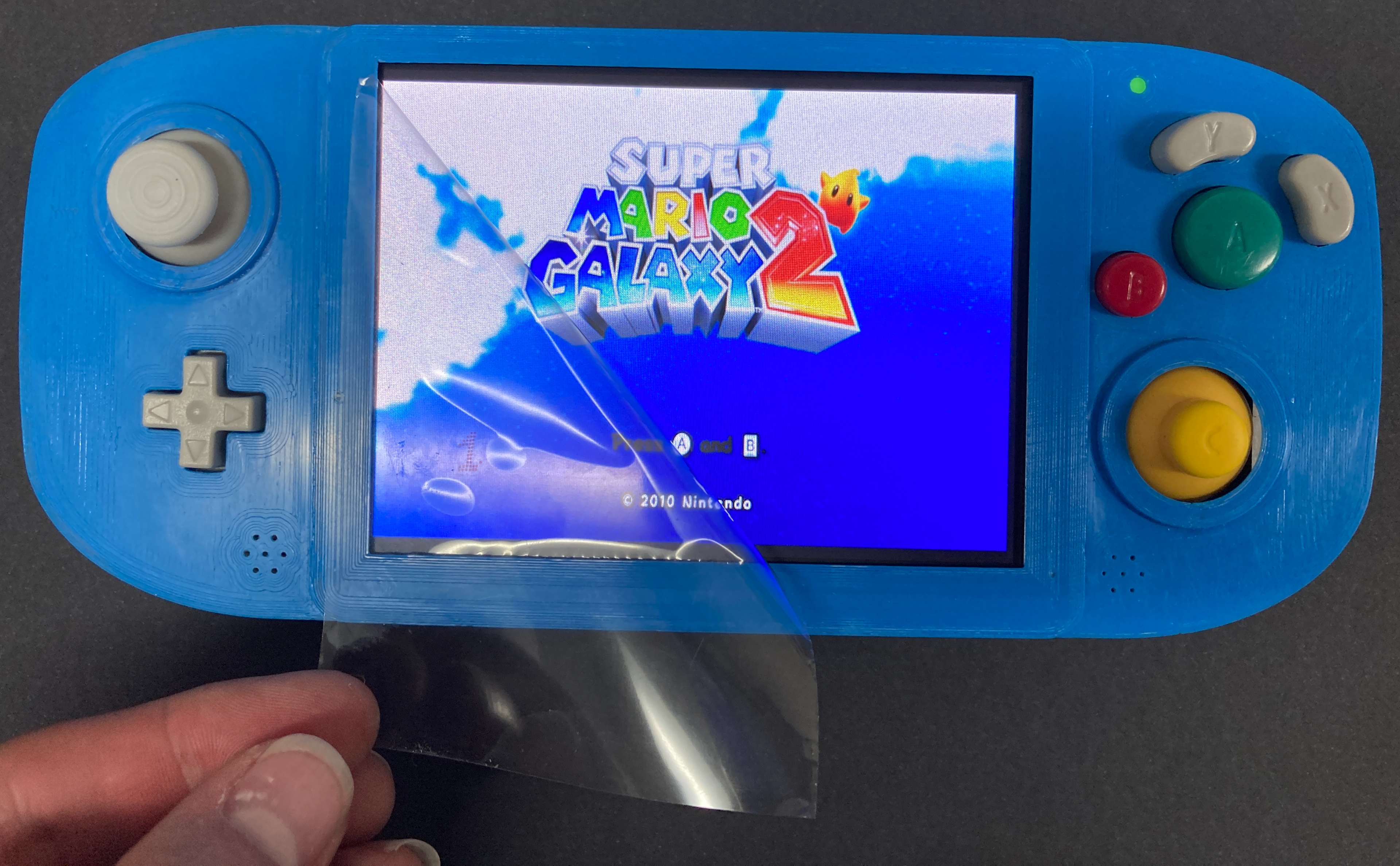
And to all those who say, why bother just get a switch (!), well can your switch play Super Mario Galaxy 2? Because this G-Wii can.
Tools Used
None of this would have been possible without the excellent tools I have been blessed to surround myself with. Thus below is a list of the tools I utilised to make this project a reality.
- Hakko FX-888D Digital Soldering Station (You are definitely going to want a temperature adjustable solder station for this build)
- Multimeter (When it doubt beep it out)
- Tweezers
- Solder (I used only 1mm diameter but would have liked to use 0.5mm for the smaller wires)
- Flux (I love the Pens just got to put the cap on them when your done)
- Solder-Wick De-Solder Braid (This in combination with Flux is the best!)
- Kapton (Polymide) Tape
- Flush Cutters (Clippers)
- Hobby Knife or Razor Blades
- Locking hemostatic forceps (I have two now)
- FFF 3D Printer and Filament (here is a guide to FFF 3D print better and I created the Shoulder buttons using a Creality LD-002R LCD Resin 3D Printer)
- Dremel with Diamond Tool Cutter
- SandPaper (Very fine Grit to smooth edges of Wii motherboard)
- Wire Stripper (spoil yourself, I didn’t and my nails suffered because of it)
- Thermal Paste
- Compartment Box (Made my life much happier)
- Little Screwdriver set (Phillip, Flathead and when disassembling the Wii a Tri-Wing Screwdriver)
Parts Required for the G-Wii
I have attempted to make this as accurate and entire as possible. There is a lot of componentry that goes into creating one of these.
- Stranded Silicone Wires (Silicone wires are great because the cover doesn’t melt ) Spoil yourself and get more colours than 2 like me
- General Thin Wire
- Magnet Wire (Two colours definitely an advantage when you start twisting them I used AWG30 mainly)
- Thicker Stranded Silicone Wire (for the batteries, I found this wire a little bit too thick but still doable )
- Tactile Buttons Tall and Stout (Tall are good as you can cut them to size)
- Squishy Silicone Buttons
- 18650 Lithium Ion Cell x 4 (You will be scratching and soldering directly to this fore-warning)
- Audio Jack
- LED RGB Clear Common Anode
- Light Dispersal Circle Plastic Part
- Laptop Repair Screw Set M2 M2.5 and M3
- Wii Console with 4 Layer Motherboard (4 Layers run cooler how to identify use this guide)
- Gamecube Controller for Buttons (I used two so I could get an extra Start button to use as the Power switch)
- At the time BitBuilt Circuit Boards. Now can source components at 4 Layer Tech (This allows you to set up the Gamecube controls, Audio Amp for Sound, Power Management, Storage and USB-C functionality for a Wii) The circuit boards I used are now open source so you can also create them from scratch
- Speakers Part # SP-1511L
- 480 7 inch screen VGA and Screen Controller
- Small Fan, Cooling Metal, and Copper Heat Dispersal Plate
- Micro-SD card and Kingston USB drive
- CPE Filament (you can also use PLA Filament just will not be as strong)
- Transparent Resin (can definitely just 3D print shoulder buttons with FFF printing)
Below is an image of my collection of parts all stored in my little compartment box. This box made me so much more efficient and it's use I cannot recommend more highly when doing project like this.
3D Printing the Case, Internal Mounting Components and Shoulder Buttons
All credit for the amazing case goes to Gunnar AKA Gman. He has open-sourced his CAD design find them here. He does incredible work (for instance he has created the World's Smallest Nintendo 64 Portable) and it is only once you build in this case do you realise how much critical thought went into each step of the way. To get a case built from scratch to this level it would take many revisions and knowledge of the whole build process (something I definitely didn’t know when I started). I modified his design slightly, making it easier for me to use threaded inserts and tiny aesthetic changes. If you’re going to alter the case to be very conscious of each millimetre you alter as by the time you're done filling it with components each and every millimetre is a precious resource.
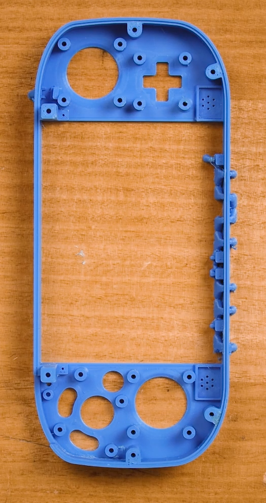
I wanted this case to last so I printed my cases using CPE and CPE + using an Ultimaker 3D Printer. For tips on how to 3D print with these materials check out this guide right here. I spent the time refining the print process till I got the exact result I was looking for. Cleaning up the case was done carefully with an Exacto knife. I wanted the back of the case to be transparent so you could see the wiring inside. I am quite happy with my result. Tips on how to improve 3D printed results with transparent filament found here. The Extra internals to mount the controls I 3D printed using either ABS or CPE. Below are some images along my way of printing and iterating this case.
I also used a Creality LD-002R LCD Printer to create the buttons. Initially, I printed them using FDM but was not happy with the colour or the layer line feel on my fingertips. I used transparent filament and coloured them with alcohol inks and Pearl Ex Powder much like this guide here. Below is an image of my initial prints which were done in black before I colourised them and an image of the buttons getting sliced in chitubox.
Research and Research
Big and very important step. BitBuilt will have your back for a lot of this. They used to have great build videos of the whole G-Wii process on youtube but sadly they have been removed. So long as I’m not stepping on any toes I have a strong desire to live stream my next G-Wii Build so others can have a video resource to work from. There is a huge amount of content to immerse yourself in. Resource links that I would recommend for specific Wii portablising check out these.
-Wii Anatomy 101 https://bitbuilt.net/forums/index.php?threads/wii-motherboard-anatomy-101.1286/
-Definitive Wii Trimming Guide https://bitbuilt.net/forums/index.php?threads/the-definitive-wii-trimming-guide.198/
-Revision Identification Guide https://bitbuilt.net/forums/index.php?threads/revision-identification-guide.863/
-Wii Basic Trimming Guide https://manual.bitbuilt.net/guide/wii-basic-trimming-guide/
-RV Loader Software (I used BBLoader but this is better) https://bitbuilt.net/forums/index.php?threads/rvloader-v1-0.4295/
-This Image for VGA Connecting https://manual.bitbuilt.net/media/photologue/photos/cache/DSC_0022_display.jpg
Software for the Wii to Portabilise It
Before you even think about pulling apart your Wii you will need to install some software to it. You need to have the homebrew channel is installed and updated on your Wii. There are a lot of guides on how to do this online. You need to use an SD card that has been FAT32 formatted. Then you need to install either BB-Loader or RV-Loader to the Wii and run it. In the Research and Research section is a guide on how to do it.
This software means that the Wii no longer requires WIFI, Bluetooth, MX Chip to Boot. Also, it will automatically send out 720x480 through the VGA. It also does a huge amount of other things as well. Aurelio is the individual behind this software and does an incredible job at making portabilising easier and more intuitive than it has ever been. Open Source Code too!
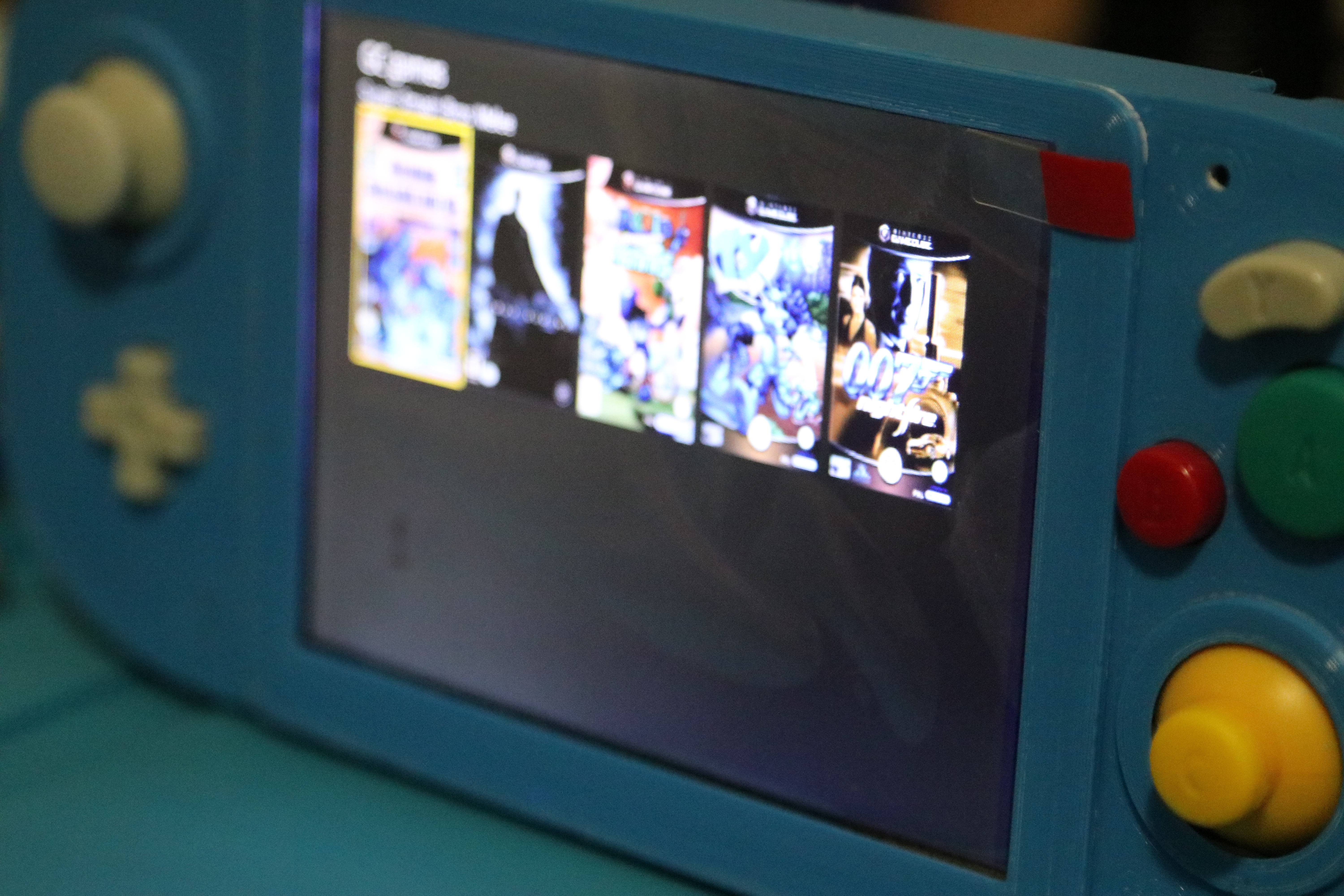
You cannot do this once the Wii has been trimmed so do it beforehand. With this software loaded you can now burn Gamecube and Wii files and place them in a folder on a USB. Then you can run the game from the USB. Thus we no longer need a CD-Rom on our Wii to play games. You will only be able to control the Wii using a Gamecube Controller at this point.
Wii on the Chopping Block
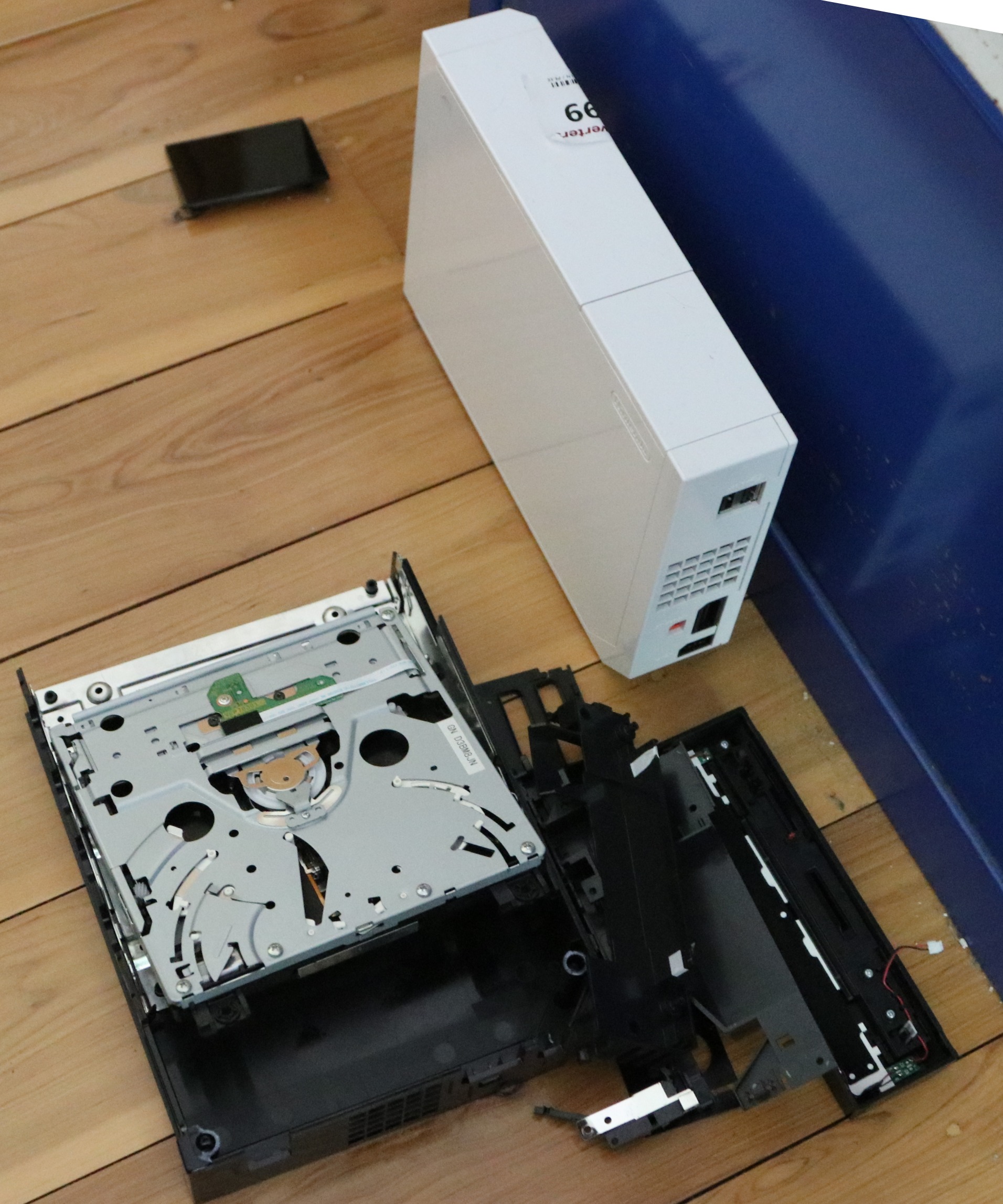
With the software all organised and some games tested on a TV screen, it's time to pull the Wii apart using mainly screwdrivers. It was surprisingly hard to pull apart, with a lot of hidden screws and I resorted to using the guide you can find in the research and research section. Below shows some steps from the process of disassembly.
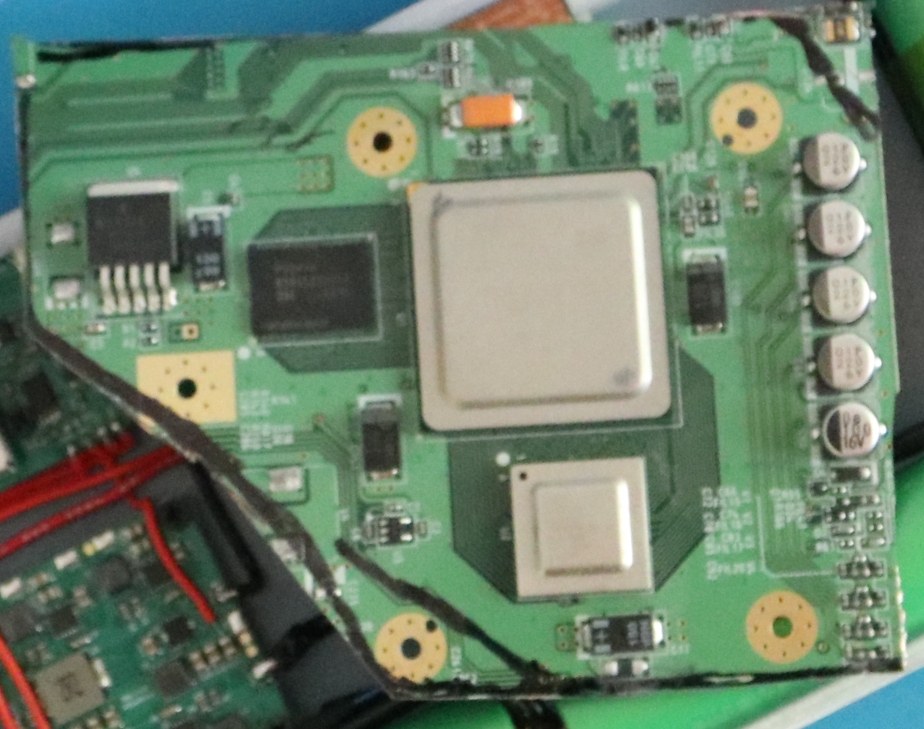
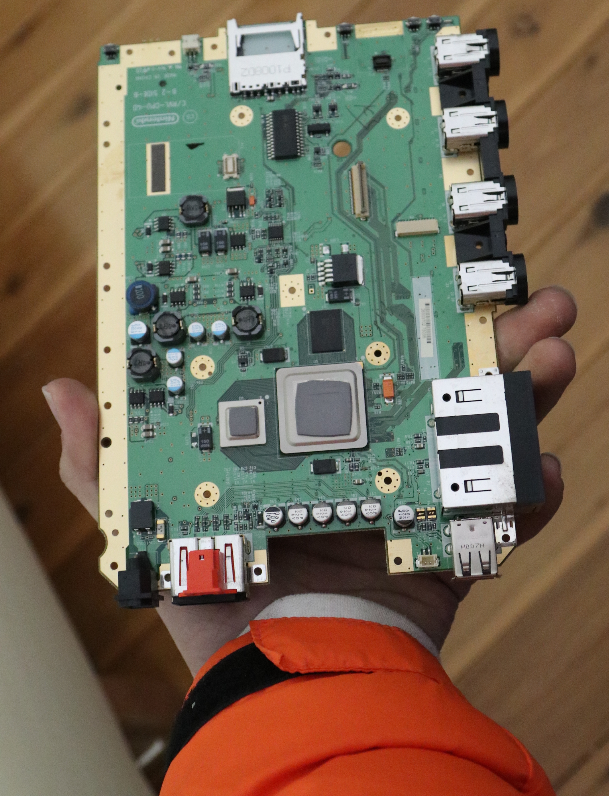
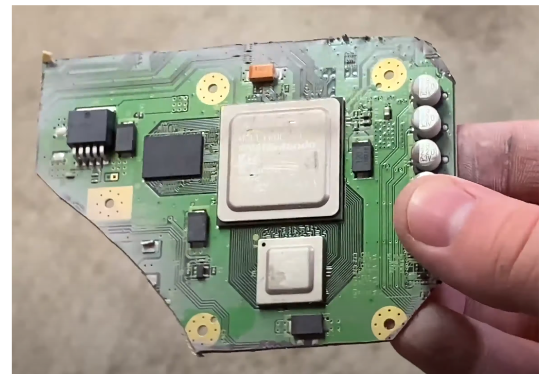
Then with the Motherboard free from its constraints I took my sharpie to cut out the main cutting then my Diamond cutter to it. An excellent video resource on how to do this can be found here (the goal is to avoid Nikey Swooshes). Take the time to sand and clean all the edges of the build. The G-Wii is a tight fit and by sanding carefully you will prevent any of the copper traces on the 4 layer board from shorting. An air compressor to clean the board would definitely be useful here. A word of safety, make sure to use respiratory protection when cutting and sanding the motherboard. Below shows a still from the video and my chopped Wii Board.
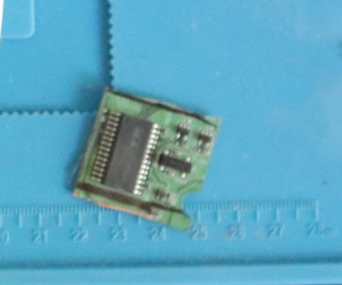
You also need to cut out the MX Chip with the U10 and U9 IC. You won't need to use the MX Chip (unless you really want to play Animal Crossing or other games that require an RTC) but the U10 Chip will need to be relocated and replace the U5 IC.
Dry Fitting Componentry
Below is what the board looks like on top of the G-Wii case and me testing out the buttons making sure they fit the case. I did many test fits throughout this build making sure that all the parts would go together the way I wanted them too. Below is me slowly taking off the edges of the Wii so it would fit the case the way I needed it to. You can also see the sharpie marks yet to be removed by isopropyl alcohol. A couple of spoilers here as the battery system has been set up.
Soldering Battery Assembly and Installing Fan
First I installed the PMS and RVL boards to the setup. These boards communicate using I2C Connections and both run on 5V. These are the red wire connections you see here. In Flux we trust, I used a lot of it for this build. As this build continues you will hopefully see my soldering improve, I took my time to make sure the wires lay down correctly, your tweezers are the best friend here. Here I also used a Start button from a game cube (shaved down just a little) captured between the case wall and the button on the RVL board. You can see this process happening in the images below.
Now I started the process of preparing the 18650s. This involved carefully scratching the top and bottoms of the batteries with a razor blade. Then with flux and solder quickly getting the solder to connect to them. Be ultra-careful! They can explode if overheated particularly if they are poor-quality batteries. Do not heat them for longer than 5 seconds and spend a long time letting them cool down. You can see the whole process of getting solder onto them below, one on the right is unscratched, one in the middle has scratches and one on the right has a solder blob.
It would be worthwhile at this point to test the voltages and amps inside each of these batteries making sure that there is not a huge variation between them. Huge variation equals sparks which are very bad so don't connect them if they are. There are a number of ground wires that you will need to attach to the bottom of PMS board from the batteries. Then you want to solder the batteries together in a 2s2p configuration. Do not connect the live power end to the battery just yet. The corners will be tight. At this point, I only had black wire of a good thickness so at this point wires that are 5V have a little bit of yellow tape wrapped around them. The images below show this.
Having achieved this we can now place the fan and copper plate into position. There are two wires coming from the fan which we will connect to the ground and 3.3 Volt on the PMS. Once that is connected our first test of the system can happen! Connect the power connection to the 5V PMS. Be smooth with this action. Then press the power button and put the case to your ear. If you can hear the fan start-up and spin you have successfully put the battery together for the G-Wii!
Having done that successfully you can turn your attention to the Wii.
Soldering Wii Assembly, Screwing it Down, and First Breath (Composite Feed + Slight Setback)
Firstly we need to relocate that U10 onto our trimmed Wii. This will supply the correct voltage and signal to the Wii so it will boot up normally and not lock itself out. This involves cutting a copper trace AND soldering with 30AWG magnet wire. You have two chances with this as the U10 works the same as the U9 but you must take your time doing this. Check the Resources section on how to do this exactly. Once complete cover the whole area in Kapton tape to keep it secure which you can see below. Then make sure to disconnect the power to the PMS so the system is no longer powered. If not you risk damaging all the componentry.
Then you can turn your attention to give the Wii the voltages it needs from the PMS. Think of the setup so far as an open sandwich with the Wii like the cheese inside. The Wii needs 5V, 3.3V, 1V, 1.15 V to boot and operate correctly so we will supply this from the PMS.
While we are at it the Screen controller needs some power too. I pulled off the large capacitor so it would run on 5 Volt which I fed up to it along with a ground wire.
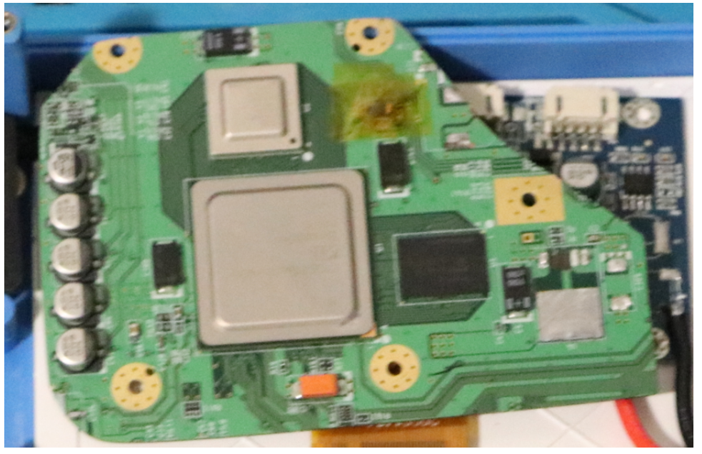
Then all we need to do is connect a wire from the composite point on the Wii to the composite of the screen and we can see if this Wii is actually still alive! Before this step, you will have no idea if your Trim was successful so seeing this screen is a huge boost to confidence! Even now it makes me smile to see. At this stage, you can also use a magnet wire to solder the data wire from the top of the Wii to the RVL board. Thus when you plug in your USB with the game data on it you will be actually able to see your games.
In my build, I had an unfortunate crack in my screen (likely from my rough handling) So I got to this stage initially and had no idea if the Wii was functional. Made for extended anxiety waiting for the new screen part to come in. You can see this in the image below.
Soldering Button Assemblies and VGA
All the buttons have a 3D printed mount that they live on and all use grey Silicone squishy buttons. The mount has holes for the ground and live pins to go through. These were slightly taller than the Orange silicon squishy buttons so little brass washers were added to make the standoffs slightly taller in the case where necessary. Time was spent also shaving down the X, Y, A, and B buttons so that they would not sit too proud of the case. Superglue was used to attach all the components together. Having dry fitted them multiple times. Below you can see images of this.
Then all the buttons including the Right and Left bummers which were all connected together on the GC2+. This board also requires ground and 3.3V and Data pin to the Wii. This data wire is a single AWG magnet wire that goes straight to the Wii Board. Amazing to me that this sends all the information to the inputs. All the ground connectors need to be connected for the D-pad and the ABXY button wires.
Once I connected up the majority of controls I turned my attention to the VGA output. VGA produces a much better image quality than composite but it does require some serious magnet wire to solve it. For the RGB of the VGA each wire must have a ground wire attached nearby. I used a drill to coil magnet wire of two different colours to achieve this. The RGB each has test pins that you can use to send the information but the other part of VGA is Horizontal and Vertical Sync which must be taken from the black brainbox. This is a very delicate operation that needs to be done with extreme care. Once all those connections are done you need to short 3.3V on the board to the video swap so that way the Wii will only display VGA. See below for a lot of the magnet wire connections that I did. All these wires need to go to the VGA output on the screen. Make sure to hot glue some strain relief as this will close together.
I did not read the Spec sheet of the screen I owned so for the first couple of attempts my colours were all wrong like below. But once I checked out the specification sheet I fixed this problem right up. See below for an image of the colours all weird looking.
Finally, we want this to produce some rad sound so work was done on the Amp. For this to work, we need to wire 4 magnet wires from the Wii to the Amp module. Then we need to supply the Amp module with 3.3 V, Ground and 1.8 volts which we source from the PMS. Then we need to connect the speakers to the R+ R- and L+ L- connectors on the Amp. At this stage, I have not given it the ability to use an aux cord (I will very soon) so to make the system think there is not Aux Short the Mic Ground and S Pads. See below for images of this.
The next step was adding a LED light to tell me how much power the system has. This has 4 wires which connect to the PMS on little pads that a named appropriately B, R, g, ~.
There are some things left to do but it was very late at this point and this was meant to be a weekend project. The Aux Cord needs to be finished and screen control settings. As a quick fix to get the settings pretty correct you can solder the screen connector that comes with the screen like in the image below and adjust the settings to what you want. Then once the settings are where you want you can unsolder the connections. Below you can see this.
Below is the final image of everything all soldered together before I closed it.
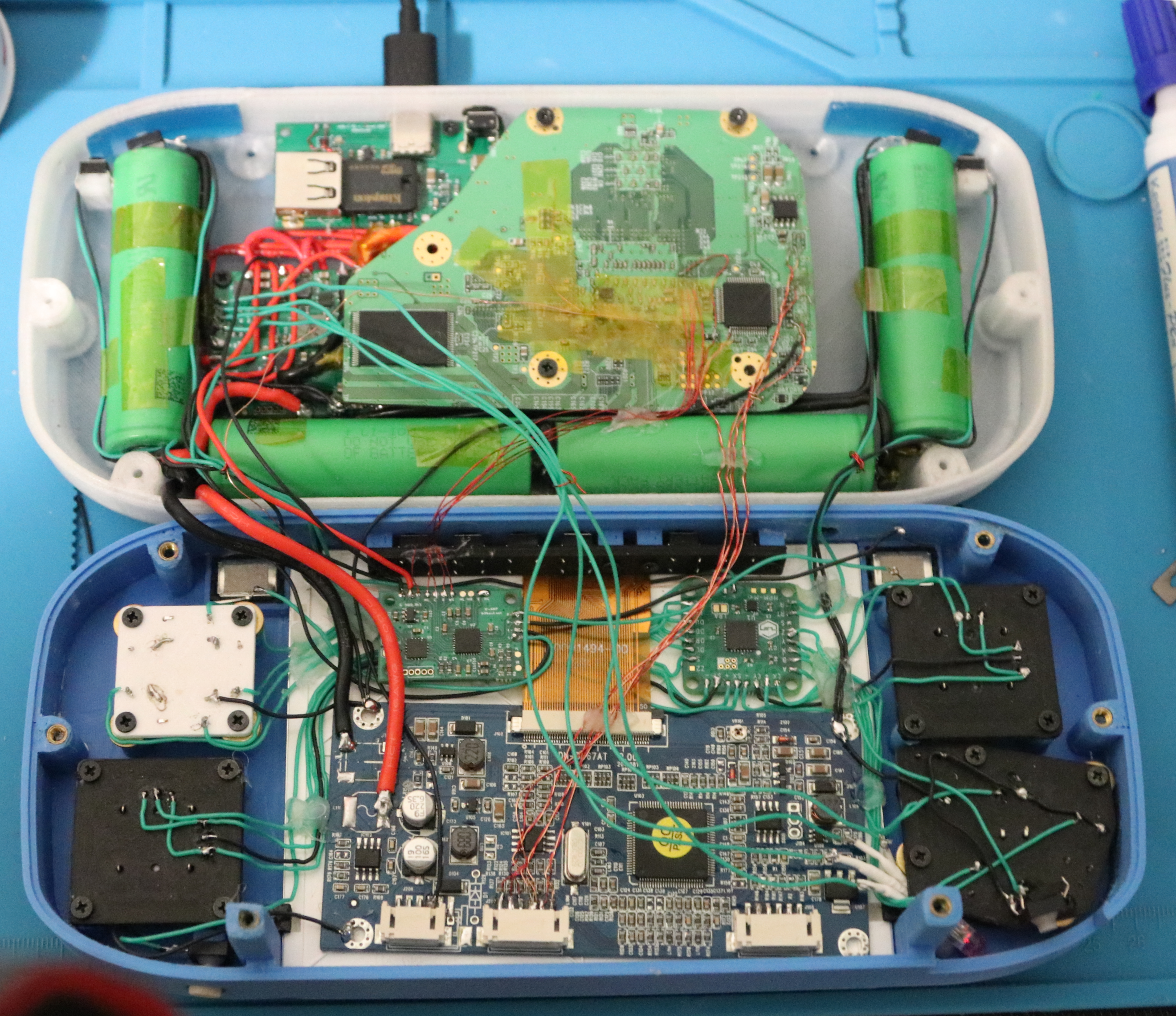
Screw It Shut
And with that I gently folded over the wires making sure none were catching on anything, screwed it shut, crossed my fingers, and turned it on. And to my amazement, it has been working ever since. Below is some glory shots.
Time for some gaming.
Update
G-Wii still running great. Has been around a year and a half of constant use. It is amazing how the portable gaming handheld world has exploded since then. Here are some completed shots of the device as it stands now. I replaced the left analogue stick with an OEM Nintendo Potentiometer stick box harvested from a Wii Nunchuck remote and it has been great ever since. The Brass Cone Washers and Brass hardware really give it a clean look and prevent the system from overheating if it's ever turned on and left flat on a surface. The CPE case has held up really well and feels softer after all the use.

