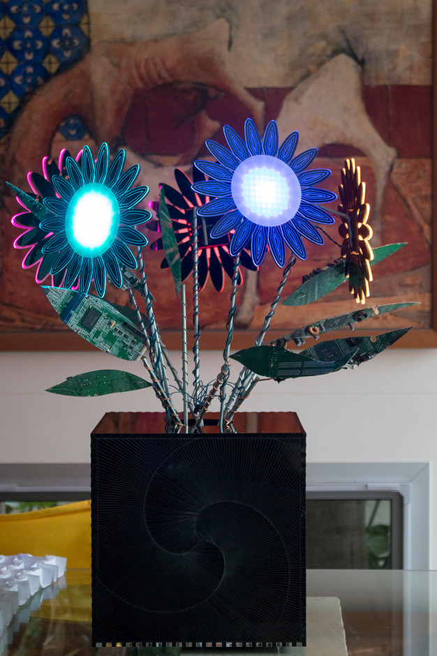
This piece combines recycled electronics extracted from decommissioned computers and new electronic components. I had an idea I wanted to incorporate a lighting element into a contemporary sculpture so it was just a matter of coming up with a theme to bring it all together.
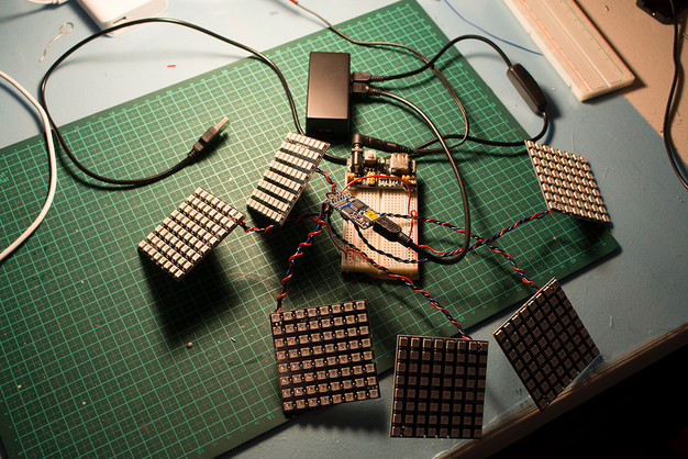
I started experimenting with 8x8 RGB LED NeoPixel matrices, which could be programmed to display any manner of digital imagery - utilising Adafruit's Fadecandy dithering controller coupled with a single board 3.3V-5V microcomputer IE Raspberry Pi Zero Wifi, Adafruit Huzzah ESP8266, Adafruit Trinket or Arduino Nano.
Parts Used:
- NeoPixel NeoMatrix 8x8
- Pi Zero W or Pi 3
- FadeCandy USB NeoPixel Driver
- Miscellaneous scrap PCBs
- Hook-up Wire
Equipment Used:
- Rotary Cutting Tool
- Laser Cutter
- Soldering Iron

A trio of decommissioned point-of-sale computers (courtesy of my neighbours) were disassembled and cleaned discarding the metal chassis.


The elements taking shape...


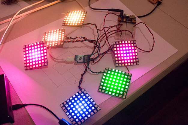
Developing and testing the python script used to drive the LED matrices...
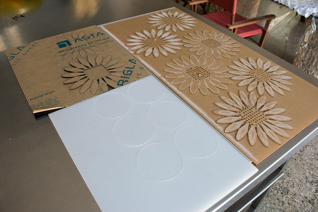
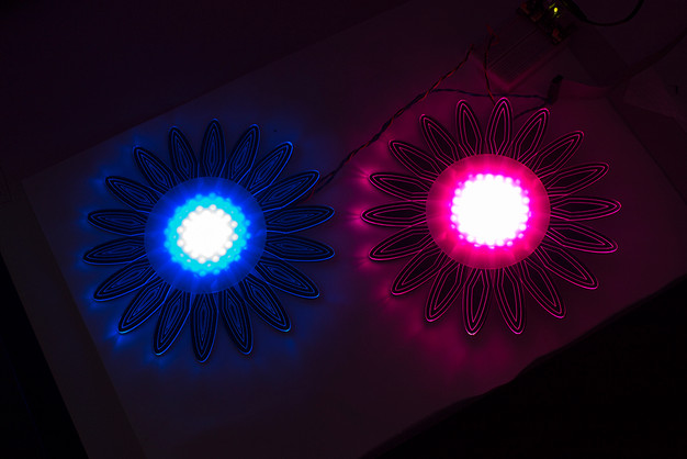
Flower design created in Illustrator and cut + etched clear acrylic sheet which will provide the body of the flower light with the etched lines employed to interrupt the light transmission creating patterned highlights.
Also testing cutting a black acrylic 'background/mount' which will provide the frame for the LED matrix while enhancing the illuminated effect through high contrast.
As the LEDs are extremely bright, I decided to cut diffuser discs out of frosted white acrylic which will soften the intensity.
Holes were cut in the transparent layer to match the LED positions. This ensures that light is 'caught' and transmitted across the perpendicular plane. Without this, the light would pass through without affecting the etched lines.
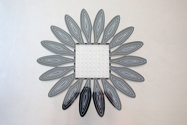
Mounting the matrix in the black acrylic background layer.

Test run of two of the assembled flowers...
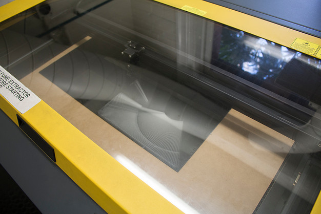
I used Solidworks to explore a design suitable for a containment vessel (vase), and went through a number of iterations; some of which are displayed below. Having settled on a finger jointed box for its simplicity and practicality, it is laser cut and etched (below left). The design is broken down into its face elements and exported as Illustrator files which can be imported into Corel Draw as required by the laser cutter...

To jazz up the otherwise basic box, I decided to create a parametric pattern using Rhinoceros's Grasshopper...

Happy with this I 'bake' the parametrically produced design and export it as an Illustrator file which is then applied to three of the boxes sides...
Laser in action cutting and etching the box design...
The assembled Raspberry Pi Zero Wifi with outboard Adafruit Fadecandy. Modularity was an important design decision and this setup enables this methodology. The 16 pin ribbon cable supports up to 8 'flowers' so while this piece currently uses 5, there is capacity to easily expand this. The RPi0W was the perfect choice... wifi enabled, linux compatible computer for less than the cost of a week's coffee, and teeny tiny!
The fadecandy board is tethered to the Pi via micro a/b USB, and power is supplied via a recycled power supply unit (PSU) from one of the old PCs used earlier. The PSU can support both the 5v - 2.5 amp requirement of the Pi as well as up to 20 amps of 5v on a separate line for the 5 x 64 LED Matrices.

I hot glued little 6mm acrylic discs as feet to the PSU which was then mounted to the inside wall of the vase/box using double sided foam tape providing a very secure grip and positions it in perfect alignment with the precut cable and ventilation holes.

I needed to be able to switch off the power but since you shouldn't just cut power to a computer (RPi0W), I added a momentary switch which is programmed to shutdown the operating system - about 5 seconds later, the power can be switched off.
The Processing program used to control the LEDs is loosely based on the grid8x8_dot matrix example in the Fadecandy github repository; which utilises the Open Pixel Connectivity protocol replicating what is drawn to screen on the LEDs.
I've set the program to autostart on powerup and runs headlessly - though can still use VNC or Putty to connect via network when needed.
The program randomly assigns colour overlays and staggers the start time of each animation. The basic 'dot' image used is the Dot.png file found in the examples directory.
On each animation iteration (fade in/out cycle), a new colour is randomly assigned. The image file is scaled to fit the matrix using a lookup table of sine wave values precalculated to reduce CPU drain while still providing realtime animated display.

Finito! (...and no water required)
Further information can be provided on request... Happy making!!!

