Despite having two high-quality variable (but analog) benchtop power supplies, I decided you can never have too many. I also specifically wanted a fixed, multi-output supply for standard project voltages such as 3.3V, 5V, 9V, 12V, as well as some negative rails for op-amps and other dual-rail components.
I picked up a handful of old (but working) PC ATX power supplies for free with just such a project in mind. These are great because people are often giving them away on Gumtree or Marketplace, so for under $20 for some regulators and connectors, you can get a nice quiet, hefty benchtop power supply. You could also use an adjustable regulator with exterior controls, but my other supplies have that covered.
What You'll Need
To complete this project you'll need some connectors. I used some banana and barrel jack connectors, but it's up to you:
-
Banana Connectors (for making cables to use)
-
Linear Regulator (I used a 9V one)
-
2 x 0.1uF Capacitor (you only need these to stabilise the regulator if you are using one)
-
Stranded Wire (this gauge will suffice for lower power, but you may want to use a heavy gauge depending on your planned current draw)
-
Indicator LED (here is a nice pack for only a few dollars)
-
Current Limiting Resistor (for the LED)
-
Power Switch (this is only to activate the output, not handle any mains power)
-
BYO Artwork. My amazing wife did mine so you're on your own for that
The Build
 It's a pretty straight forward build, but above all else, remember that you're working with a mains powered device with hefty filtering capacitors that can remain charged long after you've unplugged the power cable. Seriously, if any of that sounds unfamiliar, this may not be the project for you!
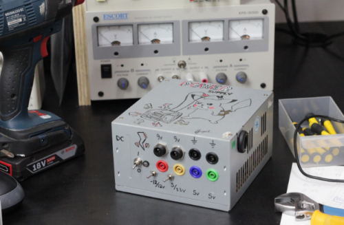
Start by drilling your holes for the supply into the front side of the panel, then mount the sockets. I used two ground reference sockets (black) and then one for each voltage and two barrel jack connectors for the 9V supply. I used a dab of hot glue to help prevent the nut from loosening over time and the socket moving around.
Now comes the wiring. ATX power supplies all use standard wiring colours, so you should be able to follow this verbatim (but it's always good to double-check using a multimeter).
-
Yellow +12V
-
Orange +3.3V
-
Red +5V
-
Blue -12V
-
White -5V
-
Black GND (ground)
Cut the wire bundles that run out of the case, leaving enough tail to reach your sockets. Wire each of the voltages to the desired socket, and wire the black ground wires to your reference sockets (black is a good idea for those). Be sure to cover any unused wires using heat shrink, and it's good practice to use heat shrink for the socket solder connectors as well.

If you plan on using a linear regulator for 9V, then connect the 12V rail to the regulator's input, the output to your socket, and a 0.1uF capacitor from the output to ground, and input to ground. I mounted mine on some stripboard using hot glue.

If you try and power on your supply, you'll notice that there is no power. That's because there is a green wire which controls the state of the supply. When disconnected, it is internally pulled high. However, when connected to ground, the supply is activated, and away you go. This provides a nice way of turning the supply off and on using a switch on the front panel, but you can always hardwire it if you wish.
So wire up your LED to turn on when the switch connects the green wire to ground, and you're all set. A good tip is to double-check the voltage before powering your project for the first time, and for extra points, you could always add some of these panel meters for visual feedback.
