|
I have a peer-reviewed study on my desk and it confidently tells me that all the capacitors on planet Earth want to be synthesisers when they grow up. To make the world a better place, let's realise the dream of four fortunate electrolytic capacitors and make a synth drone. This isn't my first time building a synthesiser, but it will be my first time building a purely analogue synth. I'm keeping it stripped down in this build. I'm keeping it stripped down in this build. I'm excited to explore melody rhythm, filtering, and enveloping later. However, right now I want something that makes noise and is simple to debug. Below I'm going to walk through the research, prototypes, unnecessary tangents, mistakes, and schematics. At the end, I'm going to use my new synth to make some wild music. Grab your coffee and ensure your smoke alarm works; let's start with some history. |

A Brief History of Those Who Came Before Me.
The fundamental principle of the oscillator I built is the reverse avalanche effect which, best as I can tell, first hit the home synthesiser world with this absolutely wild 1998 document by Williams.
To the right is an excerpt from the paper which might be the first mention of using the reverse avalanche effect to create a sawtooth pulse generator.

Source: Linear Technology; Application Note 72; May 1998; Page 34 - Authored by Jim Williams
Also in Williams’ article is this delightful drawing, which outlines alternative OPamps for his level shifter. For forty-five pages and ~16500 words Williams has meticulously measured and explained his circuit, building it up in parts, each part with a dirty under-contrasted image of an oscilloscope at nanosecond increments. The paper is focused, and it’s detailed… and he tails it with this glorious work of “90s doodle core”™ complete with a scribble to make the ink run. Amazing!
According to this Avalanche Pulse Generator article by Kerry D. Wong, the paper was pushed into the maker zeitgeist by this YouTube video by EEV blog where he recreates the avalanche effect pulse.
The idea was teased out a little further in this Mod Wiggler forum thread. In 2014 Kerry D Wong expanded on the reverse avalanche effect in this article. He tests different transistors and resistors, teasing out the finer details like minimum voltage requirements.
See also Simplest LED Flasher Circuit
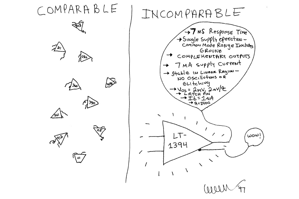
Source: Linear Technology; Application Note 72; May 1998; Page 44 - Authored by Jim Williams

It was musician LOOK MUM NO COMPUTER (Sam Battle) who refined the oscillator down to something digestible and repeatable. In a collaboration with Redbull, he was able to push the whole thing onto a stripboard in this YouTube video. The video was successful in cementing LMNC’s design and has begat many nerdy supersaw synths.
I found this (a little long-winded) 2020 article explaining the complications of this synth design. It has some nice diagrams and some useful hints. Lastly, I enjoyed this amazing website which looks like a WordArt font came to life and designed a website for a white noise machine.
Why this oscillator … oscillates.
The circuit consists of 4 team players: Capacitor, Transistor, Diode, and Resistor. They each have their role in the musical number:
- The Capacitor is what allows us to smoothly charge and discharge.
- The Transistor ensures a gradual charge and a fast discharge.
- The Diode ensures no flow from the bipolar collector
- The Resistor is setting the speed of the charge-discharge cycle, i.e. the hz, i.e. pitch.
The design relies on an effect called the Avalanche Breakdown. My understanding is that this principle applies to any insulator but in our case, we care about our transistor. I’m going to try to type this in my own words but if you would like a technical description I enjoyed reading this article.
Suppose a transistor that has no base, i.e. no way to switch it OPEN or CLOSED If you pass current into the collector the behaviour at the emitter is undefined because we don’t know the state of the gate. However, the reverse is well-defined. If you pass current into the emitter then the collector will be CLOSED because the transistor is acting as an insulator.
But, all insulators have their limits. If the “pressure” from the power source becomes too great for an insulator we can cause “an avalanche effect”. That is, a high enough voltage will cause the transistor to break down and allow the electrons through the emitter and out the collector of our imaginary base-less transistor.
This transistor doesn’t have to be imaginary, we could just chop off the base pin of a real transistor. This would give the transistor that quasi-undefined state that we were looking for above. We’re going to take advantage of that to build our sawtooth wave.
Ok, back on track! We want a simple oscillator and that means we need at least two states to switch between at a fixed rate. This deformed backward transistor is what we need because It has two states:
- one where the voltage is low and it doesn’t allow current to flow
- one where the voltage is so high we get avalanche breakdown and current flows.

At the moment we have no way of controlling when the transistor enters avalanche breakdown. This is where the capacitor comes in. Let’s have a look at my extremely technical and super professional animation which I drew using some wonky online tool.
The thing to notice is that the electrons in our circuit have two paths to ground: either through the capacitor or transistor. Unfortunately for the electrons, the transistor won’t allow current through its emitter under normal conditions. That leaves the capacitor, which accepts the electrons and charges up. However, once the capacitor has charged, the pressure in the circuit has mounted. At some unspecified point, it becomes too much and the transistor breaks down which allows current to flow through the diode and discharge the capacitor.
Now that the cap has discharged the pressure is low and eventually, the transistor finds its feet and prevents flow. Now the cycle can start all over again.
What we get is a slow gradual charge of the capacitor followed by a rapid discharge. That’s precisely what a sawtooth wave is and it is exactly what we want. We just need a probe at the anode of the capacitor and boom (metaphorically), oscillating synth.
Prototyping: Choosing a Transistor.
At the time I was building a prototype of my mono sawtooth synth I did not understand ANY of the above. I’ve lost track of the timeline a little bit here, but it’s possible I didn’t even really understand what a resistor was at that stage.
That’s cool, sometimes at the beginning we just follow instructions and we figure out what we did later.
I found that the biggest challenge of this design is delivering enough power to shift the transistor into its reverse avalanche state. Every transistor will have a different theoretical voltage where it trips and breaks down. I found that even with the same model, some transistors would need more than others.
|
In testing, some of the transistors I tried simply didn't work at all. Having explored the history and the idea of this synth, that is obvious to me in retrospect. "Of course, this process would be a little glitchy, I'm definitely not using transistors as they were intended." However, Captain Hindsight has literally never been invited to a party. I'm sure you can appreciate that, at the time I was prototyping, trying to find a transistor that even worked was very frustrating. |
In the end, I found a combination I liked. The 2N3904 NPN Switching Transistor had the right blend between reliability and consistency in tone. Its major downside was that it was very sensitive to slight variations in current. This wasn’t a problem for me, since I’m mostly making a fun toy noise machine for education. If you want to use this as a synth for an actual project or piece of music, I’d recommend the 2N2222 NPN Amp Transistor. This is now considered the standard for LMNC’s multi-oscillator banks.
Single Oscillator Schematic and Instruction
Minimum required components.
- A transistor (e.g. 2N3904)
- A ~1k Resistor
- A ~10uf Capacitor
- A minimum 10k resistor rated up to 2 watts
- An LED (orange works best for the values given above)
- Two 9v Batteries or at Least 12V
I’m going to recommend you make this all on a breadboard. Part of the charm and joy of this synth is to quickly swap components for different models and values. For example, it’s fun to try different capacitors and see how it varies the volume and pitch of the oscillator.

First things first, we want to connect the batteries in series. That’s 18V, which should be plenty of power to break down the transistor. Next, we want to pass that power through a rheostat, and for that, we will use a potentiometer.
The following statement is a fact I have always known, since birth; it has never confused me. A rheostat is just a device that can vary the current passing through it. That’s exactly what we want! Decreasing the current will slow down the rate at which the capacitor charges and the pressure builds. This will delay the decay of the transistor, slowing down the oscillation, and lowering the pitch. The reverse is also true.
The output of the rheostat should go through a 1k resistor, this just sets a healthy lower bound in ohms and leads to happy synths that never squeal.
Next, we can follow the schematic above. I used polarised capacitors in all of my oscillators but I have seen people use non-polarised capacitors online.

For sound, you could pass the output of your oscillator into your favourite pro-audio instrument amplifier and a speaker of your choice. You could even buy an instrument jack like this, grab a guitar lead, and plug the synth into your guitar amplifier. Probably would sound sick actually.
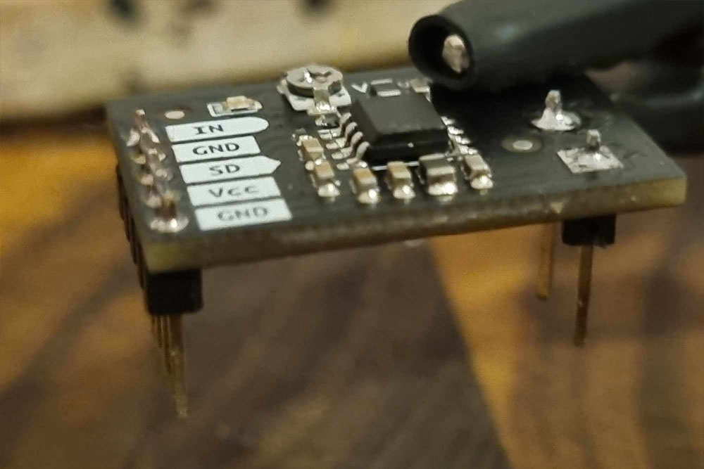
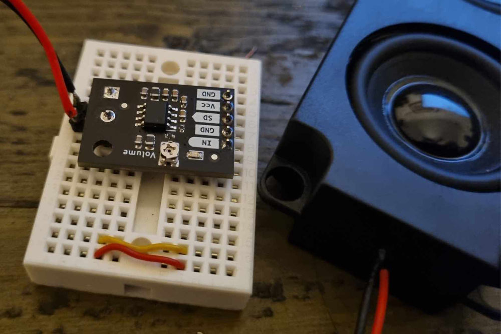
However, I decided to give the synth its own speaker. For this, we are going to rock Core’s Makerverse PAM8302 2.5W Mono Amplifier which I really enjoyed using. Any speaker will do, but I liked this 8-ohm speaker for my testing. The Makerverse amp has 5 pins.
SD stands for shutdown which we can ignore because it is active LOW and has an internal pull-down resistor.
|
IN is for your audio signal. Perfect! We are going to connect the anode of our capacitor, via a resistor, to this IN pin. |
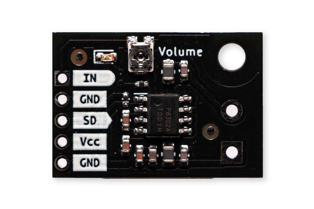
Below the IN is a GND pin, which is handy if your audio signal does not share a common ground with the power supply.
To plug in the speaker there are two rocker pin headers with a provided terminal. The screw on the top allows you to vary the volume. You, like me, might want to keep this bread-boardable. If so, I found that soldering some generic male pin headers into those speaker pins worked just fine. I then soldered some header pins onto my speaker and presto!
The last two pins are VCC and Ground. The makerverse amp wants a neat 5V which is a readily available supply. There are so many ways to power this amp board. However…
The Long Way Around: Voltage Multiplier
I have come to assume that on my fourth birthday Grandma fed me a scrumptious bowl of monkey paw soup, a soup that nourished me with the power of great curiosity... but only for the most garbage questions that absurdly overcomplicate problems otherwise easily circumnavigated with 3 minutes and a USB cable.
All tragedies in development begin with the cursed question…
“Wouldn’t it be great if ….”
In my case, humbly I thought to myself “I already have these two 9v batteries. They should have plenty of amperage to cover my entire circuit.
"Wouldn’t it be great if I could put the Arduino away and power my 5v amp with my 9v batteries?”
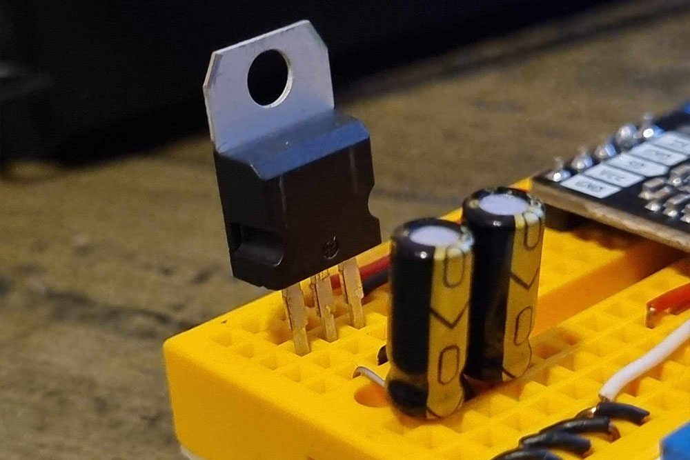
A bit of googling led me to the L7805 voltage regulator. Like a good chap, I opened up the datasheet and very quickly learned that the challenge is heat management. I didn’t love the idea of mucking around on a breadboard with a rocket hot component sitting there so I started to think about heat management solutions. I ran some back-of-the-napkin calculations with the community on the forums and learned that the L7805 would get very hot.
I knew a heat sink would help, but the monkey paw curled and curiosity struck. I started to think about additional solutions.
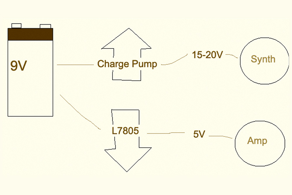
The problem: 18V to 5V is a big voltage drop but I needed 5V for my amplifier. OK, what if instead of dropping down to 5V, I started with 5V, and then built up to 18V.
I’d seen this video by Ben Eater and knew that it was possible to upscale volts. With a lot of help from the community, I managed to get it built. It took me maybe 2.5 weeks and you know what?.. It even worked.
I didn’t know this at the time, but I now know this is called a Dickson Charge Pump. I was able to take a single 9V battery, plug it into my voltage doubler, and get 19.5V which was powerful enough to push all my transistors into an avalanche. I then took that same 9V battery and punched that into an L7805 for 5V. 19.5V for the synth, 5V for the amp.
You could build a voltage multiplier too, I learned a lot doing it. With that having been said If I had my time again I’d take…
The Short Way Round
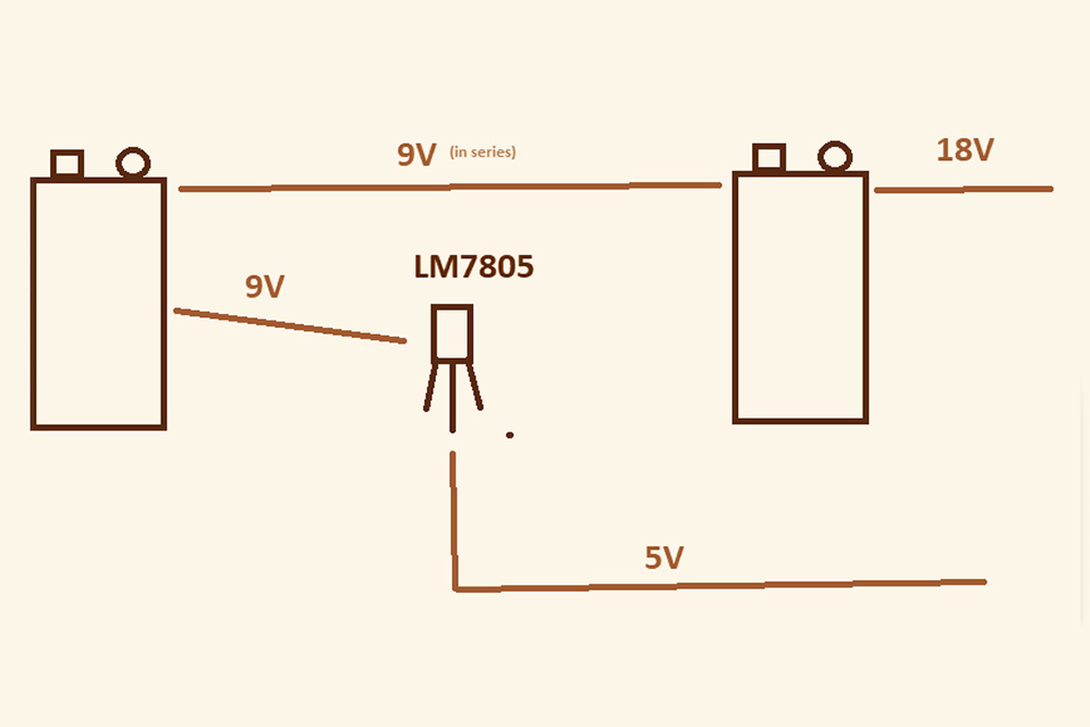
Let’s go back to the configuration where you have two batteries; BatA and BatB, each 9v. We’re going to connect these in series and that’s going to give us 18V. Remember, we’re not super keen on using our voltage regulator with 18V because we don’t want to burn ourselves while swapping our components and playing with our synth.
The thing to notice is that BatA didn’t go anywhere, we could use it for two things
- 18V by connecting BatA to another battery, BatB, in series.
- 5V by connecting BatA to the L7805 voltage regulator.
That worked. In the end, I found I got the best results by connecting BatA to the L7805 through a 3 Amp diode. Super clean 5V and 18V; no fuss. Obvious in retrospect.
Lastly, if you are going to build this synth for yourself, consider just… trusting the voltage regulator to do its job. With a heat sink, my L7805 was totally happy taking in 18V and pulling out 5V. It was a little warm, but you would have to leave your finger on it for some time for it to burn you.
If you're doing this by yourself as a fun weekend project, I say this is the way, 18V direct into the regulator. It was safe enough.
If, however, you want this to be more permanent or if you are doing this with students in an educational setting, consider the options above.
I followed this guide to configure my L7805 voltage regulator.
Putting It All Together
|
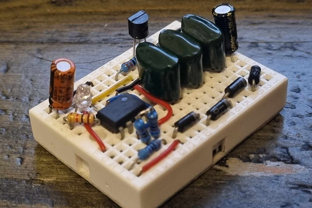
We've got the right amount of power for our components, we've got the basic theory. Below is a schematic that shows off all the basic concepts for the synthesizer. The best values for the capacitors ended up being between 4uf and 12uf. I always needed a minimum 10k ohm resistor on the output. I enjoyed giving each of my oscillators different strengths resistors and capacitors. This gave the resulting chord a richer texture because each oscillator had a different timbre. Sometimes I had to wiggle around the potentiometer to start the first avalanche off, after which it was self-sustaining. |

|
Here are the components that I used for my final design. Most are available in the Core Electronics store. Consider that the joy of this synth is to experiment so don't hesitate to buy alternate values for your components. |

| PART # | DESCRIPTION | QT | ||
| CE05337 | 9V Battery | 2 | ||
| CE05205 | 9V Battery Clip | 2 | ||
| CE05631 | Breadboard Wire | 1 | ||
| CE05142 | 170 Mini Breadboard | 4 | ||
| 2N4904 | NPN Transistor | 4 | ||
| CE09096 | 10k Potentiometers | 4 | ||
| CE05130 | 63V 22uf Electrolytic Cap | 1 | ||
| CE05130 | 25V 10uf Electrolytic Cap | 2 | ||
| CE05130 | 63V 4.7uf Electrolytic Cap | 1 | ||
| CE05130 | 16V 10uf Electrolytic Cap | 2 | ||
| ADA4293 | 100 Ohm Resistor | 4 | ||
| CE09886 | 10k Ohm Resistor | 4 | ||
| CE08576 | LEDs (any colour) | 4 | ||
| CE08263 | Makerverse PAM8302 AMP | 1 | ||
| CE08483 | 5 Watt 8 Ohm Speaker | 1 | ||
| COM-00107 | 5 Volt Voltage Regulator | 1 | ||
| ADA977 | TO220 Clip-on Heat Sink | 1 | ||
Let’s Make Some Music!
See below a cute little demo I whipped up to show off what this skipper can sound like.
- In this mp3 I used the Analogue QuadOSC Drone for all of my sounds.
- For some tone control, I used the Waldorf 2-pole analogue filter.
- To help boost the volume for recording I used the Focusrite ISA Preamp.
- For percussion, I used the Elektron Digitakt Drum Machine.
- My DAW was Cycling 74's MaxMSP.
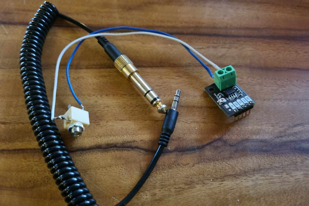
To pull audio out, I found a little 3.5mm audio jack like this. I soldered some wire to the tip and ground of the jack and tinned the other side so it would fit in my Makerverse amplifier terminal block. Now I could just reach for an aux cable whenever I wanted to record the synthesiser.
I was super impressed by how many qualities the sound possessed. I think I could get that tone out of my commercial synthesisers, but it would take me ages to program. Dialling in this homebrew synth came really naturally. Honestly just mucking around on it led to so many unexpected cool noises. Great toy.
To extract some movement from the synth I just grabbed a screwdriver and manipulated the volume control on the Makerverse amplifier while I recorded. Because it takes some time to tune the drone I had to muck around a little bit with my tape. The cuts were easy and nothing much was left on the floor. If you make your own track, I’d love to hear it. Please share it in the comments.
I had a lot of fun making this.
If you're more experienced than me, (and resist trying to re-invent the 5v power supply), then you can knock this over in a weekend.
Good luck; happy making.
Pix ❣️