This project is to allow remote control of my pool and associated lights with a dedicated display in
the house, a phone application and Amazon Alexa. Any and/or all of these input devices may be used
to control the pool. The pool temperature and the status of the control devices are monitored as
additional information.
The base system installed by the pool company consisted of an AstralPools VX chlorinator and a
Viron P320 multispeed pump. To turn on the spa for example you had to go to the pool equipment
enclosure and manually change the pool mode from “auto” to “on”, turn the valve to direct water to
the spa, and manually set the pump speed to “high”.
It all runs from Arduino and an ESP8266!
All the code and extras are available on GitHub.
Parts List
Most of the parts I used for this project were collected from various online sources, you can find the full build of materials and links to the parts I used in the PDF that's attached to this project (down the bottom of the page).
However, there are some parts that you can pick up from Core Electronics:
- Relays
- Displays
- ESP8266
- Network Cables
- 3D Printed Parts Service
- Laser Cutting Service for Acryllic parts
- Arduino Nano Boards
- Buck converter
- Assorted Components
The System
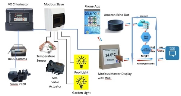
The schematic above shows the logical connectivity of the systems, which can be divided into three
fundamental categories being, the standard Astralpools functionality, the Modbus Slave local control
device and the Modbus Master remote display device.
Standard AstralPools Functionality
The first stage of the project is to enable communication between the VX chlorinator and the Viron
multispeed pump. This is achieved by the addition of the Viron BLDC communications module.
Once installed you need to:
- Enable “Fast Comms” on the Viron pump.
- Enable “Fast Comms” on the VX chlorinator.
- Select “3 speed pump enable” on the VX chlorinator.
Once this is done additional configuration menus on the VX chlorinator are shown which enable the
operator to associate the desired pump speed with the mode of operation. In this case for normal
chlorination (pool mode auto), then a low speed 1 is desired, while when spa operation (pool mode
on) is requested, then high speed 3 is desired.
Note: The communications between the VX chlorinator and viron pump in Australia is not MODBUS.
Although Astralpools in Europe does support the viron pump with MODBUS, the Australian version is
a proprietary protocol.
MODBUS Slave Local Control Device
The local control device is installed in the pool equipment enclosure adjacent to the VX chlorinator
and viron pool pump. This device is essentially a Arduino Nano microcontroller which supports the
inputs (temperature and pool status) and the digital outputs for the valves and lights. The
microcontroller is also programmed as a Modbus slave for communication to the Modbus master
display controller.
The microcontroller is programmed using the Arduino IDE software on windows.

The microcontroller is programmed using the Arduino IDE software on windows.
- Arduino Nano microcontroller PCB
- 24VDC power supply (power for both local controller, interface module and remote display controller)
- 24VAC power supply for Jandy valve actuator
- 4 x Relay modules for the valve and lights control
- A standard 12 pole IP54 electrical enclosure with DIN rail mounting
- 2 x panel mounted electrical sockets for the light connections.
In addition there is a VX Chlorinator interface module PCB (below) which is installed into the
chlorinator itself to provide the local I/O control and connected to the Modbus slave local controller
via a standard RJ12 six core cable.
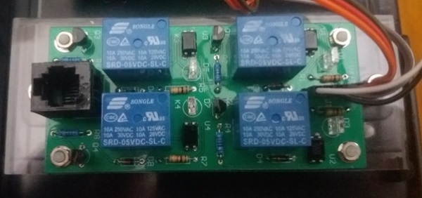
Below shows the interface module installed into the VX chlorinator

MODBUS Master Remote Display Device
The Remote display device is a 3.5 inch Nextion touch screen mounted into a custom 3D printed
enclosure to house the touch screen and the Modbus master PCB. Power and communications are
provided by a standard RJ45 CAT5e network cable connected to the Modbus slave controller.
Modbus communications are via one pair of the CAT5e cable using RS485 communication modules
with two pairs being used for the 24VDC power.
The display allows the remote monitoring and control of all the connected pool devices. In addition
the display also has two timers associated with the lights to enable automatic on/off control of the
lights. The timers in the VX Chlorinator are still used for the automatic control of the pool
chlorination.
The Modbus master PCB has been sized to match that of the Nextion 3.5” display so that it can be
attached together via standoffs and mounted together into the custom 3D printed housing. The
housing is a similar size to a standard electrical outlet with identical mounting holes so that standard
electrical mounting plates can be used for fixing.
The microcontroller is programmed using the Arduino IDE software on windows.
The major components of the Modbus master display controller include:
- ESP8266 NodeMCU microcontroller PCB
- Nextion 3.5” touch display
- Custom 3D printed wall mount enclosure


Mobile Phone App
The ESP8266 NodeMCU microcontroller also runs a webserver to support the mobile phone
application client. This supports the same monitoring and control functionality as the dedicated
display with the exception of the additional automatic timers.
The mobile phone application was made using the MIT App Inventor 2 software, which supports
applications for android devices and can be added for download on the google playstore.
If the user wants an application for apple phones the same code can be used with the Thunkable
software (ie the same owner as MIT App Inventor 2). Thunkable applications can be used on both
android and apple phones.

DIY with Amazon Alexa
The ESP8266 NoneMCU microcontroller also runs webservers / clients to support the Alexa
functionality. This is separated into two parts. The first part is a Belkin switch device emulator which
allows Alexa to directly control the spa, pool lights and garden lights. With the Modbus Master
controller powered and connected to the home wifi and internet, then upon Alexa device discovery
then the three above devices are automatically added to Alexa.
For example:
User asks:
“Alexa, turn the spa on”
Alexa Response:
“ok”, The spa valve will go to the spa position.
The second part of the Alexa functionality is for the reporting of the pool status information. This
status information is sent to the thingspeak IOT service every 1 minute (configurable) via the MQTT
publish service . The custom Alexa skill then interacts with the thingspeak IOT to respond to Alexa
requests for information. The Pool Mode commands are sent to the Modbus master controller via
the MQTT subscribe service.
For example:
User asks:
“Alexa, ask my pool, check the status”
Alexa Response:
“The temperature is 25.5 celsius. Mode is auto. Spa if off. Pump is on.”

Configuration by the user of the local wifi SSID and password details, as well as the thingspeak
settings to enable the Alexa functionality is achieved via a dedicated wifi manager which is initiated
by a pushbutton at the back of the Modbus Master controller.
Configuration by the user of the local wifi SSID and password details, as well as the thingspeak
settings to enable the Alexa functionality is achieved via a dedicated wifi manager which is initiated
by a pushbutton at the back of the Modbus Master controller.
Note the Alexa functionality should only be enabled if the thingspeak account has been fully setup.
.
Schematics
All of the schematics I designed are also available in the project PDF, linked at the end of the project (down the bottom of this page)
Final Project!

If you've got any questions, please let me know!

