The aim of this project was to create a working model of the aircraft exterior lighting systems. Initially, this started as a simple project for Uni, but I wasn’t having that. I wanted to learn something. So of course, I went over the top. Being my first big electronics project, I wanted to do it analogue, so that I could learn a bit more about components and such.
It uses four 555 Timer circuits (two 555's and a 556) to flash and blink the lights, somewhat consistent with that of an Airbus. Two of the timers are in the astable configuration, and the others are in the monostable configuration. It mimics the operation of the Beacon, Anti-collision strobe, Navigation lights and landing lights. Each of these functions can be individually switched on and off. It runs off of 5V DC, so it can be powered by USB or a powerbank to be mobile.
Bill of materials
- 2 x 555 Timer chips and bases
- 1 x 556 Timer chip and base
- 6 x white, 1 x orange, 1 x red, 1 x green 5 mm LED
- 4 x SPDT toggle switches
- 1 x SPDT slide switch
- 1 x 2.1 mm DC Jack
- 1 x circuit board or Protoboard
- 4 x 10 uF tantalum capacitors, 4 x 0.01 uF polyester capacitors, 1 x 0.001 uF ceramic capacitor, 1 x 220 uF electrolytic capacitor
- 0.1” connectors, 2x4 and 2x5 right angle blocks
- 5 x general purpose NPN transistors, I used BC 548, had them lying around
- A range of resistors, 1 x 470 ohm resistor, 1 x 510 ohm resistor, 8 x 1 k resistors, 1 x 5.1 k resistor, 2 x 7.5 k resistors, 1 x 9.1 k resistors, 1 x 10 k resistor, 1 x 33 k resistor, 1 x 47 k resistor, 1 x 51 k resistor, 1 x 56 k resistor
- M3 hardware, washers, short bolts.
- 3D printed parts
- 9 x LED bezels, 5mm
- Acrylic lid
- DC power cable to USB cable.
- Miscellaneous wire, heat-shrink, and cable ties
The first step was to first get some ideas. I knew that I wanted to make it as realistic as possible so I looked for a double flash strobe circuit. As it happens, someone had already made one with 555 Timers. This was a great place to start.
I built this circuit on the breadboard to confirm that it worked, which it did. Big thanks to my brother who just so happened to have all of the right components to make it. At this point, I didn’t really understand how to use components such as transistors and capacitors so some time was spent trying to find out how they worked.
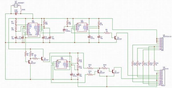
From there I read the 555 Timer datasheet to get an understanding of how the circuit worked. It also happened that the datasheet had some circuits on to demonstrate the chip's uses. It outlined the two main configurations that the Timer is normally used in, monostable and astable. The strobe circuit uses two chips in monostable configuration to give a high and low duty cycle. I then applied the second astable configuration to act as a delay to trigger the beacon. After much trial and error, playing around on the breadboard, and testing ideas, I came up with this circuit.

The timing of the circuit was determined based on the lighting sequence of the Airbus. To adjust the timing, you change the values of the resistors and capacitors that are connected to the discharge, threshold, and trigger pins. These values were calculated based on the equations in the datasheet. A calculator on Digi-Key’s website was used to speed up the process.
The circuit was then made and tested on the breadboard. Minor timing changes were then made to confirm the correct operation. At the time we didn’t have the correct sizes of resistors so we just made them combining multiple in series.
It was then made on a piece of Vero board or Perf board.
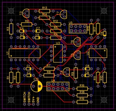
Once the operation of the circuit on the Vero board was confirmed, I started to turn the schematic into a PCB. This involved making some footprints for most of the components as I could not find them in the libraries in EasyEDA. Then once the components were arranged on the board the traces were run.

Once that was finished the PCBs were ordered through JLC PCB and the long anxious wait began. They took about two weeks to get here. Once I got them, they were populated with all of the components and tested.
I designed a box in Solidworks that could be 3d printed. The top was made out of acrylic and was CNC routed. I made the tolerances between the lid and the box a bit too tight so some fettling was required. I also made a model of the PCB with all of the components. Probably the biggest waste of time but hey, you get these cool pictures. The bezel mounts for the LEDs were at angles, an attempt to convey a somewhat realistic viewing angle to that on a real aircraft.
The switches and LEDs were then wired up on their separate looms and inserted into the lid. I accidentally wired the switches upside-down. I wanted them to be on when you flick them up but instead, they are on when you flick them down. Oh well. It still worked as intended and looked pretty cool too.


