
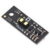

Pololu Digital Distance Sensor with Pulse Width Output, 300cm Max, Side-Entry Connector
Available with a lead time
Expect dispatch between Jul 21 and Jul 24
Quantity Discounts:
- 10+ $33.51 (exc GST)
- 25+ $32.46 (exc GST)
|
|


This compact sensor makes it possible to measure the distance of objects up to about 300 cm (120") away using a simple digital pulse width interface (similar to a hobby servo control signal). It uses a short-range lidar module to precisely measure how long it takes for emitted pulses of infrared, eye-safe laser light to reach the nearest object and be reflected back, allowing for 2 mm resolution. As long as the sensor is enabled, it takes continuous distance measurements and encodes the ranges as the widths of high pulses, which can then be timed by a microcontroller using a single digital input.
 |
 |
A camera with no IR filter shows the infrared light emitted by a Pololu Digital Distance Sensor. |
|---|
The relationship between measured distance d (in mm) and pulse width t (in µs) is as follows:
d=4 mm1 µs·(t
t = 1000 text( µs) + (1 text( µs)) / (4 text( mm)) * d
The timing uncertainty is approximately ±5%. As objects approach the sensor, the output pulse width will approach 1.0 ms, while an object detected at 300 cm will produce a 1.75 ms pulse width. The sensor uses a pulse width of 2.0 ms to indicate no detection. The pulse period T ranges from around 30 ms to 33 ms, depending on the proximity of the detected object.
The maximum detection range depends on object reflectivity and ambient lighting conditions. In Pololu's tests, the sensor was able to reliably detect a wall out to around 300 cm away, a white sheet of paper out to around 170 cm, and a hand out to around 100 cm. The following graph shows the measured distances of three units versus their actual distances from a variety of targets at several different ranges:
 |
Please note that while this sensor can detect objects to within about 1 mm of the sensor face, the effective minimum distance it can measure is around 4 cm, so objects closer than 4 cm might result in an inaccurate measurement.
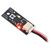
This sensor features a side-entry 3-pin male JST SH-style connector that works with Pololu's 3-pin JST SH-style cables. A functionally identical version is also available with 0.1"-pitch through-holes instead of a connector.
Specifications
 |
- Operating voltage: 3.0 V to 5.5 V
- Current consumption: 30 mA (typical) when enabled, 0.4 mA when disabled
- Maximum range: approximately 300 cm (120") (for high-reflectivity targets in good ambient conditions; lower-reflectivity targets or poor ambient conditions will reduce the maximum detection range)
- Minimum range: 4 cm (for accurate measurement); < 1 mm (for detection)
- Update rate: 30 Hz to 33 Hz (33 ms to 30 ms period)
- Field of view (FOV): 15° typical; can vary with object reflectance and ambient conditions
- Output type: digital pulse width
- Connector: side-entry 3-pin male JST SH-style that is compatible with Pololu's 3-pin JST SH-style cables
- Dimensions: 0.9" × 0.35" × 0.22" (22.9 × 8.9 × 5.6 mm); see the dimension diagram (290k pdf) for more information
- Weight: 0.02 oz (0.5 g)
Using the sensor
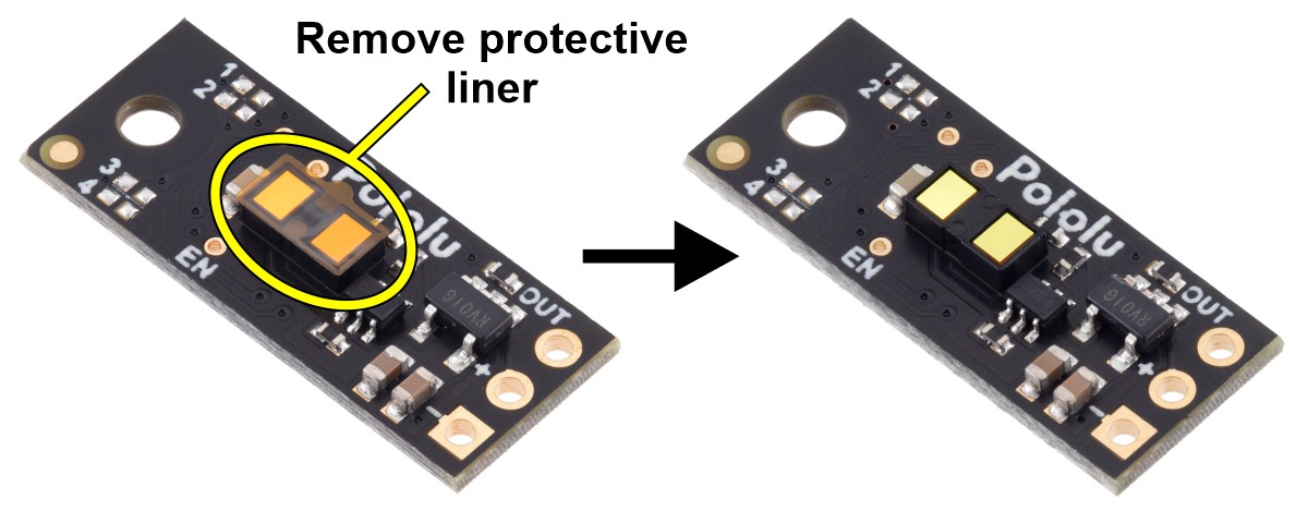 |
Important note: This product might ship with a protective liner covering the sensor IC. The liner must be removed for proper sensing performance.
Three connections are necessary to use this module: VIN, GND, and OUT. These pins are accessible through the board’s 3-pin male JST SH-style connector, which is compatible with Pololu's 3-pin JST SH-style cables. When used with Pololu's cables, the red wire connects to VIN, the black wire connects to GND, and the white wire connects to OUT. The VIN pin should be connected to a 3 V to 5.5 V source, and GND should be connected to 0 volts. The OUT pin drives low (0 V) when an object is being detected and it drives high (to the VIN level) when an object is not being detected. It is weakly pulled high when the sensor is disabled or waiting for its first reading to complete after power-up. A red LED on the back side of the board also lights whenever an object is detected.
 |
The board has an optional ENABLE pin that can be driven low to put it into a low-power state that consumes approximately 0.4 mA. This pin can be accessed through a via or its neighboring surface-mount pad on the back side labeled “EN” on the silkscreen. The ENABLE pin is pulled up to VIN, enabling the sensor by default.
The board has one mounting hole intended for use with #2 or M2 screws.
Arduino program for reading pulse width output
This is a simple Arduino sketch that reads the output of the Pololu Distance Sensor with Pulse Width Output, 130cm Max and displays the measured distance in millimeters.
| 1 2 3 4 5 6 7 8 9 10 11 12 13 14 15 16 17 18 19 20 21 22 23 24 25 26 27 28 29 30 31 32 33 34 35 36 | // Example Arduino program for reading the Pololu Distance Sensor with Pulse Width Output, 130cm Max// Change this to match the Arduino pin connected to the sensor's OUT pin.constuint8_t sensorPin = 2;voidsetup(){ Serial.begin(115200);}voidloop(){ int16_t t = pulseIn(sensorPin, HIGH); if(t == 0) { // pulseIn() did not detect the start of a pulse within 1 second. Serial.println("timeout"); } elseif(t > 1850) { // No detection. Serial.println(-1); } else { // Valid pulse width reading. Convert pulse width in microseconds to distance in millimeters. int16_t d = (t - 1000) * 2; // Limit minimum distance to 0. if(d < 0) { d = 0; } Serial.print(d); Serial.println(" mm"); }} |
micro:bit MakeCode program for reading pulse width output
Pololu have also created a MakeCode example program for the BBC micro:bit single-board computer that demonstrates how to read and convert the output of the Pololu Distance Sensor with Pulse Width Output, 300cm Max. The program’s output can be viewed in the MakeCode device console, which also plots the readings on a graph. You can open the program in the micro:bit MakeCode editor by clicking this link or the picture below.

Jumper settings (irs17a/irs17b)
The board features four surface-mount configuration jumpers that determine its operation mode. Different versions of the Pololu Digital Distance Sensors ship with the appropriate jumpers pre-populated with 0 O resistors. These resistors can be desoldered from the populated spots or solder bridges can be added across the unpopulated spots to convert one sensor version into another. This sensor can be converted into any other irs17a/irs17b version as listed in the following table. (For more information about how the different output types work, see the product pages for representative versions.)
| irs17a/irs7b jumper settings | |||||||
| Item # | Description | Maximum range* | Hysteresis | Resolution | Minimum update rate | Jumper settings (4321) | |
|---|---|---|---|---|---|---|---|
| no connector | side-entry connector | ||||||
| #4066 | #5480 | Digital output, 25cm | 25 cm | 50 mm | - | 100 Hz | 0000 |
| #4067 | #5481 | Digital output, 50cm | 50 cm | 50 mm | - | 100 Hz | 0001 |
| Digital output, 75cm | 75 cm | 50 mm | - | 100 Hz | 0010 | ||
| #4069 | #5483 | Digital output, 100cm | 100 cm | 50 mm | - | 100 Hz | 0011 |
| Digital output, any detect | ~130 cm | - | - | 100 Hz | 0100 | ||
| #4071 | #5485 | Pulse width output, 130cm max | ~130 cm | - | 1 mm (= 0.5 µs) | 100 Hz (110 Hz max) | 0101 |
| Digital output,125cm | 125 cm | 50 mm | - | 30 Hz | 1000 | ||
| Digital output,150cm | 150 cm | 50 mm | - | 30 Hz | 1001 | ||
| Digital output,175cm | 175 cm | 50 mm | - | 30 Hz | 1010 | ||
| #4077 | #5491 | Digital output, 200cm | 200 cm | 50 mm | - | 30 Hz | 1011 |
| Digital output, any detect | ~300 cm | - | - | 30 Hz | 1100 | ||
| #4079 | #5493 | Pulse width output, 300cm max | ~300 cm | - | 2 mm (= 0.5 µs) | 30 Hz (33 Hz max) | 1101 |
* Effective range depends on object reflectivity and ambient lighting conditions.
Item numbers in this table indicate versions that Pololu offer for sale as standard products, but Pololu can manufacture the other versions on demand (or even make sensors with custom firmware for you). If you are interested in customization, please contact us.
The Pololu Digital Distance Sensor family
Pololu have several versions of Pololu Digital Distance Sensors with different ranges, operating modes, and connector options:
| Digital output (does not provide distance measurement) | |||||||
| Item # | Maximum range1 | Minimum range | Minimum update rate | Jumper settings (4321) | PCB ID | ||
|---|---|---|---|---|---|---|---|
| no connector | side-entry connector | ||||||
| #4050 | 5 cm | < 5 mm | 145 Hz | 0000 | irs16a | ||
| #4052 | 10 cm | < 5 mm | 115 Hz | 0010 | |||
| #4054 | 15 cm | < 5 mm | 95 Hz | 0100 | |||
| #4066 | #5480 | 25 cm | < 1 mm | 100 Hz | 0000 | irs17a/b | |
| #4067 | #5481 | 50 cm | < 1 mm | 100 Hz | 0001 | ||
| #4069 | #5483 | 100 cm | < 1 mm | 100 Hz | 0011 | ||
| #4077 | #5491 | 200 cm | < 1 mm | 30 Hz | 1011 | ||
| Pulse width output (provides distance measurement) | ||||||||
| Item # | Maximum range1 | Minimum range2 | Resolution | Minimum update rate | Jumper settings (4321) | PCB ID | ||
|---|---|---|---|---|---|---|---|---|
| no connector | side-entry connector | |||||||
| #4064 | ~50 cm | 1 cm | 3 mm | 50 Hz | 1110 | irs16a | ||
| #4071 | #5485 | ~130 cm | 4 cm | 1 mm | 100 Hz | 0101 | irs17a/b | |
| #4079 | #5493 | ~300 cm | 4 cm | 2 mm | 30 Hz | 1101 | ||
Note 1: Effective range depends on object reflectivity and ambient lighting conditions.
Note 2: Objects closer than the minimum distance can still be detected, but the measured distance might be inaccurate. The minimum detection range is < 5 mm for irs16a boards and < 1 mm for irs17a boards.
These are the output graphs for the digital output versions that just report if an object is in their detection range:
 |
 |
 |
 |
 |
 |
 |
The output graph is a bit different for the versions that use a pulse width to encode the measured distance. The output for these versions is similar to hobby servo control signals and is shown below as a function of time:
|
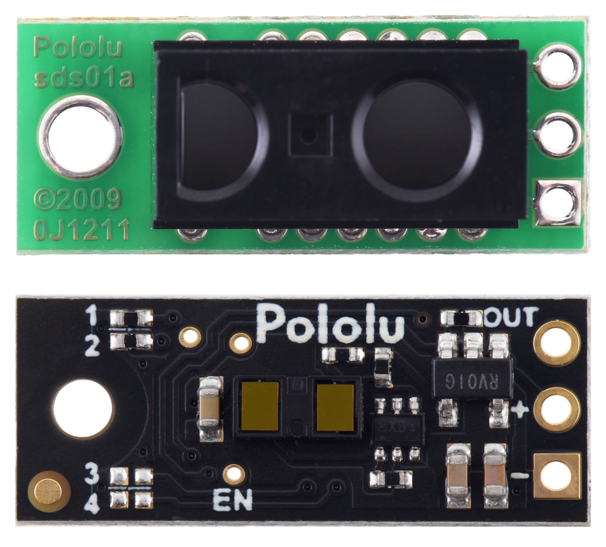
Comparison to Sharp Digital Distance Sensors
The Pololu Digital Distance Sensors have nearly the same form factor and pinout as Pololu's carrier boards for the Sharp/Socle GP2Y0D8x digital distance sensors. They are available in the same 5 cm, 10 cm, and 15 cm ranges, in addition to longer ranges of up to several meters. This means they can be used as replacements for these older modules, which are based on sensors from Sharp/Socle that are no longer in production, and the longer-range versions can serve as upgrades that provide enhanced detection and measurement capabilities. The sensors on these newer units are much thinner than the Sharp modules, so the zero-range point is approximately 7 mm closer to the PCB, and the beam angle of the newer units is wider. The pictures below show side-by-side comparisons of the two:
|
|
|

Dimensions
| Size: | 0.9" × 0.35" × 0.22" |
|---|---|
| Weight: | 0.5 g |
General specifications
| Resolution: | 2 mm |
|---|---|
| Maximum range: | 300 cm1 |
| Sampling rate: | 30 Hz2 |
| Minimum operating voltage: | 3.0 V |
| Maximum operating voltage: | 5.5 V |
| Connector: | side-entry, 3-pin JST SH-type |
| Supply current: | 30 mA3 |
| Output type: | digital pulse width |
Identifying markings
| PCB dev codes: | irs17b |
|---|---|
| Other PCB markings: | 0J15469 or 0J15601 |
Notes:
- 1
- This maximum is only achievable for high-reflectance objects in good ambient conditions; lower-reflectivity targets or poor ambient conditions will reduce the maximum range.
- 2
- Minimum.
- 3
- Typical average current draw when enabled; disabling via the EN pin reduces it to around 0.4 mA.
File downloads
Dimension diagram of the Pololu Digital Distance Sensor with Side-Entry Connector (290k pdf)
3D model of the Pololu Digital Distance Sensor with Side-Entry Connector (4MB step)
Drill guide for the Pololu Digital Distance Sensor with Side-Entry Connector (13k dxf)
This DXF drawing shows the locations of all of the board’s holes.
Exact shipping can be calculated on the view cart page (no login required).
Products that weigh more than 0.5 KG may cost more than what's shown (for example, test equipment, machines, >500mL liquids, etc).
We deliver Australia-wide with these options (depends on the final destination - you can get a quote on the view cart page):
- $3+ for Stamped Mail (typically 10+ business days, not tracked, only available on selected small items)
- $7+ for Standard Post (typically 6+ business days, tracked)
- $11+ for Express Post (typically 2+ business days, tracked)
- Pickup - Free! Only available to customers who live in the Newcastle region (must order online and only pickup after we email to notify you the order is ready). Orders placed after 2PM may not be ready until the following business day.
Non-metro addresses in WA, NT, SA & TAS can take 2+ days in addition to the above information.
Some batteries (such as LiPo) can't be shipped by Air. During checkout, Express Post and International Methods will not be an option if you have that type of battery in your shopping cart.
International Orders - the following rates are for New Zealand and will vary for other countries:
- $12+ for Pack and Track (3+ days, tracked)
- $16+ for Express International (2-5 days, tracked)
If you order lots of gear, the postage amount will increase based on the weight of your order.
Our physical address (here's a PDF which includes other key business details):
40 Aruma Place
Cardiff
NSW, 2285
Australia
Take a look at our customer service page if you have other questions such as "do we do purchase orders" (yes!) or "are prices GST inclusive" (yes they are!). We're here to help - get in touch with us to talk shop.
Have a product question? We're here to help!
 Solderless Breadboard - 400 Tie Points (ZY-60)SKU: CE05102 Brand: Core ElectronicsPerfect for prototyping.
- Solderless Breadboard - 830 Tie Points (ZY-201)SKU: CE05314 Brand: Core ElectronicsSolid construction with handy binding posts.
-
-


Videos
View AllGuides

Effective Ways To Measure Distance In Maker Projects

DIY 2D and 3D Spatial Tracking with Ultra-Wideband | Arduino & Pico Guide

Getting Started With Ultra-Wideband & Measuring Distances| Arduino & Pico Guide

The Maker Revolution
Projects

WhyzaGC - Feather ESP32 addon to the MightyOhm Gieger Counter

IR Break-Beam Stopwatch

Makers love reviews as much as you do, please follow this link to review the products you have purchased.
Product Comments