
MP6500 Stepper Motor Driver Carrier, Digital Current Control
In stock, ships same business day if ordered before 2PM
Delivered by Tue, 28th of Jul
Quantity Discounts:
- 10+ $14.57 (exc GST)
- 25+ $14.12 (exc GST)
 |
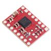
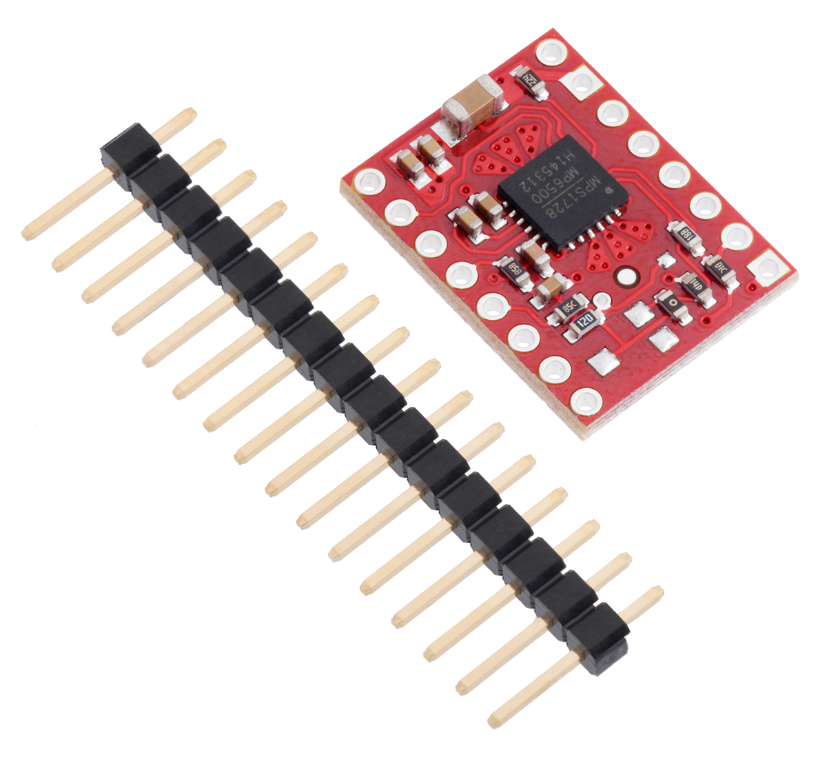
MP6500 Stepper Motor Driver Carrier, bottom view. |
|---|
This product is a carrier board or breakout board for the MP6500 stepper motor driver from Monolithic Power Systems (MPS); Pololu therefore recommend careful reading of the MP6500 datasheet (1MB pdf) before using this product. This stepper motor driver lets you control one bipolar stepper motor at up to approximately 1.5 A per phase continuously without a heat sink or forced air flow (see the Power dissipation considerations section below for more information). Here are some of the driver’s key features:
- Simple step and direction control interface
- Four different step resolutions: full-step, half-step, 1/4-step, and 1/8-step
- Adjustable current control lets you set the maximum current output, which lets you use voltages above your stepper motor’s rated voltage to achieve higher step rates
- Two current limit control options available, each with two header pin assembly options, making four versions in all:
- Potentiometer Current Control uses an on-board trimmer potentiometer to set the current limit up to 2.5 A
- Digital Current Control allows a microcontroller to dynamically adjust the current limit up to around 2 A
- Internal current sensing allows the driver to automatically adjust the decay mode as necessary to provide the smoothest current waveform
- 4.5 V to 35 V supply voltage range
- Can deliver 1.5 A per phase continuously without additional cooling
- Built-in regulator (no external logic voltage supply needed)
- Can interface directly with 3.3 V and 5 V systems
- Over-temperature thermal shutdown, over-current shutdown, short circuit protection, and under-voltage lockout
- 4-layer, 2 oz copper PCB for improved heat dissipation
- Exposed solderable ground pad below the driver IC on the bottom of the PCB
- Module size, pinout, and interface match those of Pololu's A4988 stepper motor driver carriers in most respects
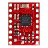
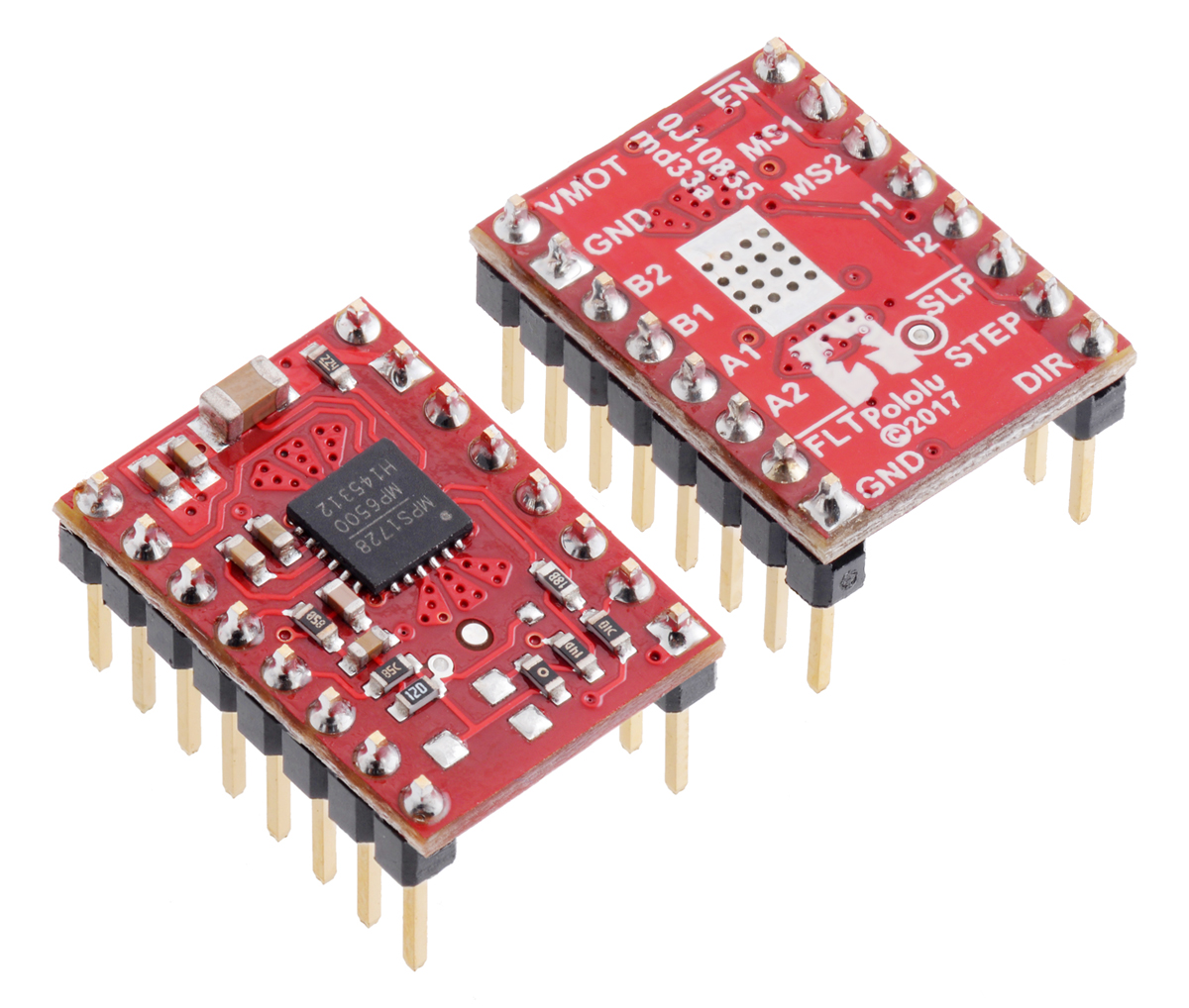
This product ships with all surface-mount components—including the MP6500 driver IC—installed as shown in the product picture.
Some unipolar stepper motors (e.g. those with six or eight leads) can be controlled by this driver as bipolar stepper motors. For more information, please see the frequently asked questions. Unipolar motors with five leads cannot be used with this driver.
Details for item #2968
This version of the MP6500 Stepper Motor Driver Carrier offers digital current control through its I1 and I2 inputs, which allows a microcontroller to make dynamic current limit adjustments. See the Current limiting section below for more details on controlling the current limit.
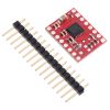
Header pins are included but not soldered (see item #2969 for a version of this carrier with header pins already installed).
Included hardware
The MP6500 stepper motor driver carrier ships with one 1×16-pin breakaway 0.1" male header. The headers can be soldered in for use with solderless breadboards or 0.1" female connectors. You can also solder your motor leads and other connections directly to the board.
|
|
Using the driver
 |
Basic wiring diagram for connecting a microcontroller to an MP6500 Stepper Motor Driver Carrier, Digital Current Control (full-step mode). |
|---|
Power connections
The driver requires a motor supply voltage of 4.5 V to 35 V to be connected across VMOT and GND. This supply should have appropriate decoupling capacitors close to the board, and it should be capable of delivering the expected stepper motor current. The driver has an internal voltage regulator, so it does not require a logic voltage supply.
Warning: This carrier board uses low-ESR ceramic capacitors, which makes it susceptible to destructive LC voltage spikes, especially when using power leads longer than a few inches. Under the right conditions, these spikes can exceed the 40 V absolute maximum voltage rating for the MP6500 and permanently damage the board, even when the motor supply voltage is as low as 12 V. One way to protect the driver from such spikes is to put a large (at least 47 µF) electrolytic capacitor across motor power (VMOT) and ground somewhere close to the board.
Motor connections
Four, six, and eight-wire stepper motors can be driven by the MP6500 if they are properly connected; a FAQ answer explains the proper wirings in detail.
Warning: Connecting or disconnecting a stepper motor while the driver is powered can destroy the driver. (More generally, rewiring anything while it is powered is asking for trouble.)
Step (and microstep) size
Stepper motors typically have a step size specification (e.g. 1.8° or 200 steps per revolution), which applies to full steps. A microstepping driver such as the MP6500 allows higher resolutions by allowing intermediate step locations, which are achieved by energizing the coils with intermediate current levels. For instance, driving a motor in quarter-step mode will give the 200-step-per-revolution motor 800 microsteps per revolution by using four different current levels.
The resolution (step size) selector inputs (MS1 and MS2) enable selection from the four step resolutions according to the table below. These two pins are pulled low through internal 500 kO pull-down resistors, so the driver defaults to full-step mode when these inputs are left disconnected. For the microstep modes to function correctly, the current limit must be set low enough (see below) so that current limiting gets engaged. Otherwise, the intermediate current levels will not be correctly maintained, and the motor will skip microsteps.
| MS1 | MS2 | Microstep Resolution |
|---|---|---|
| Low | Low | Full step |
| High | Low | Half (1/2) step |
| Low | High | Quarter (1/4) step |
| High | High | Eighth (1/8) step |
Control inputs
Each pulse to the STEP input corresponds to one microstep of the stepper motor in the direction selected by the DIR pin. These inputs are both pulled low by default through internal 500 kO pull-down resistors. If you just want rotation in a single direction, you can leave DIR disconnected.
The chip has two different inputs for controlling its power states: SLEEP and ENBL. For details about these power states, see the datasheet. Please note that the driver pulls both of these pins low through internal 500 kO pull-down resistors. The default SLEEP state prevents the driver from operating; this pin must be high to enable the driver (it can be connected directly to a logic “high” voltage between 2.5 V and 5 V, or it can be dynamically controlled by connecting it to a digital output of an MCU). The default state of the ENBL pin is to enable the driver, so this pin can be left disconnected.
The datasheet does not describe how SLEEP and ENBL affect the driver’s internal logic, but based on Pololu's testing, bringing SLEEP low disables and resets the entire driver (including the microstep position) while bringing ENBL high disables only the motor outputs while retaining the microstep position.
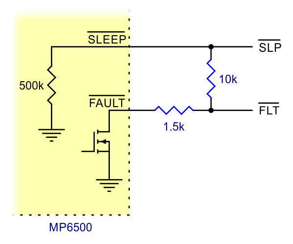 |
Schematic of nSLEEP and nFAULT pins on MP6500 carrier. |
|---|
The MP6500 also features an open-drain FAULT output that drives low whenever the H-bridge FETs are disabled as the result of over-current protection, over-voltage protection, thermal shutdown, or under-voltage lockout protection. The carrier board connects this pin to the SLEEP pin through a 10 kO resistor that acts as a FAULT pull-up whenever SLEEP is externally held high, so no external pull-up is necessary on the FAULT pin. Note that the carrier includes a 1.5 kO protection resistor in series with the FAULT pin that makes it is safe to connect this pin directly to a logic voltage supply, as might happen if you use this board in a system designed for the pin-compatible A4988 carrier. In such a system, the 10 kO resistor between SLEEP and FAULT would then act as a pull-up for SLEEP, making the MP6500 carrier more of a direct replacement for the A4988 in such systems (the A4988 has an internal pull-up on its SLEEP pin).
As a consequence of the connection between SLEEP and FAULT, active faults can pull the SLEEP pin low (below 2.1 V) if it is not externally pulled up strongly enough. Pololu recommend any pull-up resistor used with SLEEP be 4.7 kO or stronger (or just connect SLEEP directly to VCC).
Current limiting
To achieve high step rates, the motor supply is typically higher than would be permissible without active current limiting. For instance, a typical stepper motor might have a maximum current rating of 1 A with a 5 O coil resistance, which would indicate a maximum motor supply of 5 V. Using such a motor with 9 V would allow higher step rates, but the current must actively be limited to under 1 A to prevent damage to the motor. You will typically want to set the driver’s current limit to be at or below the current rating of your stepper motor.
This version of the MP6500 carrier (as opposed to the one with a potentiometer) uses the I1 and I2 inputs to set the current limit. For coarse control, these inputs can be driven low or set to high-impedance to provide four different limit settings in increments of approximately 500 mA:
| I1 | I2 | Current Limit |
|---|---|---|
| Z | Z | 0.5 A |
| Low | Z | 1 A |
| Z | Low | 1.5 A |
| Low | Low | 2 A |
A pin can be set to high-impedance by leaving it disconnected or, if it is connected to a microcontroller, by configuring the microcontroller pin as an input. If both I1 and I2 are disconnected, the current limit defaults to 0.5 A.
For finer control, an analog voltage or a PWM can be supplied to the I1 pin while I2 is driven low:
|
|
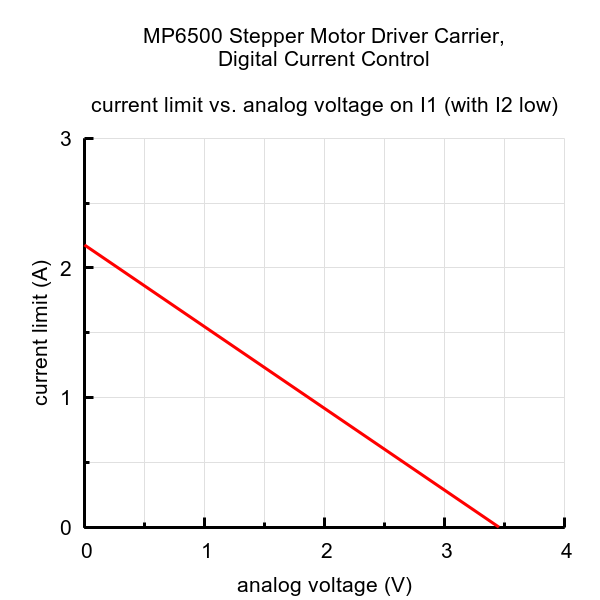
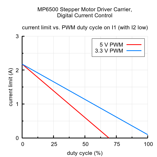
The equation for these curves is:
Pololu recommend using a PWM frequency of 1 kHz or greater.
In practice, Pololu have often observed the actual current limit when using analog or PWM control to be about 10% (sometimes up to 15%) lower than what the equation and graphs show. However, when driving the I1 and I2 pins digitally for coarse control, the current limiting circuit should produce fairly accurate 0.5 A steps as indicated in the table above.
The VREF node on this version of the MP6500 Stepper Motor Driver Carrier does not mean anything; it will always be between around 0.8 V and 1 V.
Note: The coil current can be very different from the power supply current. If you want to confirm that your current limit setting matches what you expect, the appropriate place to put your current meter is in series with one of your stepper motor coils. If the driver is in full-step mode, both coils will always be on and limited to approximately 70% of the current limit setting. If your driver is in one of the microstepping modes, the current through the coils will change with each step, ranging from 0% to 100% of the set limit. See the MP6500 datasheet for more information.
Current limiting circuit changes: As of 28 April 2021, Pololu are changing some of the component values in the current limiting circuit to reduce the time it takes for the current limit to stabilize on driver startup in certain situations (from about half a second to less than 100 ms). This change should not affect the behavior of the board otherwise. The new component values are reflected in the updated schematic diagrams. Please note that you might receive either the old or the new version until Pololu complete this transition.
Power dissipation considerations
The MP6500 driver IC has a maximum current rating of 2.5 A per coil, but the actual current you can deliver depends on how well you can keep the IC cool. The carrier’s printed circuit board is designed to draw heat out of the IC, but to supply more than approximately 1.5 A per coil, a heat sink or other cooling method is required. Note that the version of this board with digital current control has a maximum current limit setting of around 2 A.
This product can get hot enough to burn you long before the chip overheats. Take care when handling this product and other components connected to it.
Please note that measuring the current draw at the power supply will generally not provide an accurate measure of the coil current. Since the input voltage to the driver can be significantly higher than the coil voltage, the measured current on the power supply can be quite a bit lower than the coil current (the driver and coil basically act like a switching step-down power supply). Also, if the supply voltage is very high compared to what the motor needs to achieve the set current, the duty cycle will be very low, which also leads to significant differences between average and RMS currents. Additionally, please note that the coil current is a function of the set current limit, but it does not necessarily equal the current limit setting as the actual current through each coil changes with each microstep.
Schematic diagram
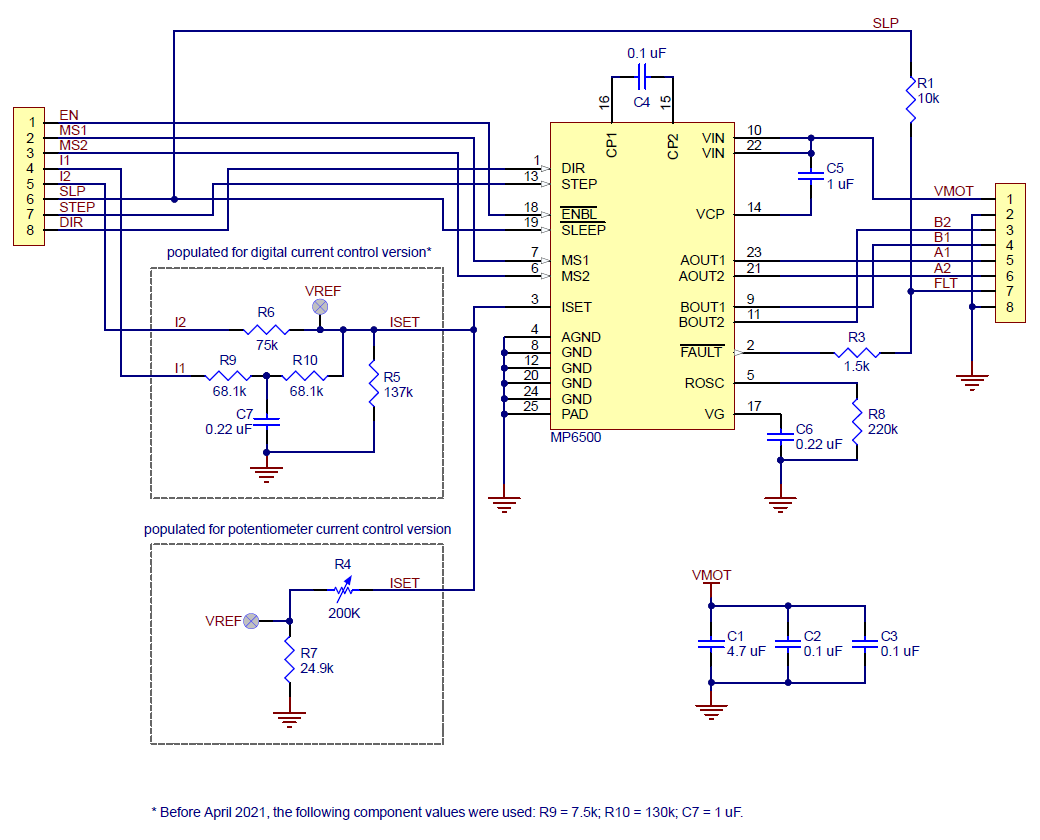 |
Schematic diagram for the MP6500 Stepper Motor Driver Carrier. |
|---|
This schematic is also available as a downloadable pdf (106k pdf).
People often buy this product together with:
 | Pololu Universal Aluminum Mounting Hub for 5mm Shaft, #4-40 Holes (2-Pack) |
 | Stepper Motor: Bipolar, 200 Steps/Rev, 42×38mm, 2.8V, 1.7 A/Phase |
 | MP6500 Stepper Motor Driver Carrier, Potentiometer Current Control |
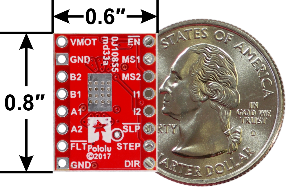
Dimensions
| Size: | 0.6" × 0.8" |
|---|---|
| Weight: | 1.4 g1 |
General specifications
| Minimum operating voltage: | 4.5 V |
|---|---|
| Maximum operating voltage: | 35 V |
| Continuous current per phase: | 1.5 A2 |
| Maximum current per phase: | 2 A3 |
| Minimum logic voltage: | 2.1 V4 |
| Maximum logic voltage: | 6 V5 |
| Microstep resolutions: | full, 1/2, 1/4, and 1/8 |
| Current limit control: | digital |
| Reverse voltage protection?: | N |
| Header pins soldered?: | N |
Identifying markings
| PCB dev codes: | md33a, md33b |
|---|---|
| Other PCB markings: | 0J10855, 0J11019 |
Notes:
- 1
- Without included optional headers.
- 2
- Without a heat sink or forced air flow.
- 3
- With sufficient additional cooling. This limitation comes from maximum achievable current limit setting on this version of the board.
- 4
- This is the input logic high threshold.
- 5
- Absolute maximum voltage on any input is 6.5 V.
File downloads
-
MPS Application Note AN120: Understanding MP6500 Current Control (1MB pdf)
-
Schematic diagram of the MP6500 Stepper Motor Driver Carrier (106k pdf)
-
Dimension diagram of the MP6500 Stepper Motor Driver Carrier (216k pdf)
-
Drill guide for the MP6500 Stepper Motor Driver Carrier (41k dxf)
This DXF drawing shows the locations of all of the board’s holes.
-
3D model of the MP6500 Stepper Motor Driver Carrier, Potentiometer Current Control (5MB step)
-
3D model of the MP6500 Stepper Motor Driver Carrier, Digital Current Control (5MB step)
Recommended links
Exact shipping can be calculated on the view cart page (no login required).
Products that weigh more than 0.5 KG may cost more than what's shown (for example, test equipment, machines, >500mL liquids, etc).
We deliver Australia-wide with these options (depends on the final destination - you can get a quote on the view cart page):
- $3+ for Stamped Mail (typically 10+ business days, not tracked, only available on selected small items)
- $7+ for Standard Post (typically 6+ business days, tracked)
- $11+ for Express Post (typically 2+ business days, tracked)
- Pickup - Free! Only available to customers who live in the Newcastle region (must order online and only pickup after we email to notify you the order is ready). Orders placed after 2PM may not be ready until the following business day.
Non-metro addresses in WA, NT, SA & TAS can take 2+ days in addition to the above information.
Some batteries (such as LiPo) can't be shipped by Air. During checkout, Express Post and International Methods will not be an option if you have that type of battery in your shopping cart.
International Orders - the following rates are for New Zealand and will vary for other countries:
- $12+ for Pack and Track (3+ days, tracked)
- $16+ for Express International (2-5 days, tracked)
If you order lots of gear, the postage amount will increase based on the weight of your order.
Our physical address (here's a PDF which includes other key business details):
40 Aruma Place
Cardiff
NSW, 2285
Australia
Take a look at our customer service page if you have other questions such as "do we do purchase orders" (yes!) or "are prices GST inclusive" (yes they are!). We're here to help - get in touch with us to talk shop.
Have a product question? We're here to help!
 Mini Stepper Motor - 200 Steps - 20x30mm NEMA-8 SizeSKU: ADA4411 Brand: AdafruitThis tiny stepper motor is the same quality and step-size as the big NEMA-17's A ...
- 3401 Series Set Screw Round Belt Pulley (4mm Bore, 16mm PD)SKU: GB-3401-0004-0016 Brand: goBildaA 16mm PD 3401 Series Set Screw Round Belt Pulley (4mm Bore)
- 3401 Series Set Screw Round Belt Pulley (4mm Bore, 8mm PD)SKU: GB-3401-0004-0008 Brand: goBildaA 8mm PD 3401 Series Set Screw Round Belt Pulley (4mm Bore)
- 3401 Series Set Screw Round Belt Pulley (5mm Bore, 16mm PD)SKU: GB-3401-0005-0016 Brand: goBildaA 16mm PD 3401 Series Set Screw Round Belt Pulley (5mm Bore)


- Adafruit A4988 Stepper Motor Driver Breakout BoardSKU: ADA6109 Brand: AdafruitStepper motors are used for CNC machines, 3D printers, and whenever else one nee ...

Videos
View AllGuides

The Maker Revolution

Motor Drivers vs. Motor Controllers
Projects

3D Printed Pico Weather Display

Makers love reviews as much as you do, please follow this link to review the products you have purchased.
Product Comments