In this guide, we will be learning how to use a GPS module with the Raspberry Pi Pico and MicroPython. We will be looking at; how GPS works, how to wire up and code the Pico to use the GPS module, and as a final step we will be putting it all together with a quick little project - a device that takes your current position and points you in the direction of a target destination anywhere on earth, also telling you how far away it is.
We also have a version of this guide for the Arduino and C++ if that is more your style.
Let's get into it!
How does GPS Work?
GPS is one of the most incredible things we as a species have made. Figuring out where you are used to be a skill our ancestors spent a considerable portion of their lives mastering, but now you can do it far more precisely with a GPS module (like in the image on the right) that costs a little more than a cup of coffee. But how does it work? How does such an inexpensive module have the ability to locate you anywhere on Earth?
Well, this is thanks to a system of strategically placed GPS satellites orbiting around the Earth, about 30 of them. And these satellites are constantly beaming out radio messages containing the exact time the signal was sent, and where the satellite is in orbit. These satellites aren't stationary - they're constantly moving in a medium Earth orbit at around 20,000 km above us, completing two full orbits every day. Although they are constantly moving, their strategic placement means that every part of the earth can see 4 to 15 of them.

With that multi-billion dollars of equipment already in space, this inexpensive device just listens for those messages and uses that information to figure out how far away each satellite is, which it calculates using the speed of light. The module measures the time delay between when the signal was sent (as reported by the satellite) and when it was received. Since radio waves travel at the speed of light (roughly 300,000 km per second), the delay tells us the distance. Pretty clever, right?
If it can get this distance from 4 or more satellites at once, it can figure out its latitude, longitude, altitude, and even get a very accurate time reading from the satellite's atomic clock. That's another incredible thing - this module is going to let your project read the time from an atomic clock in space!
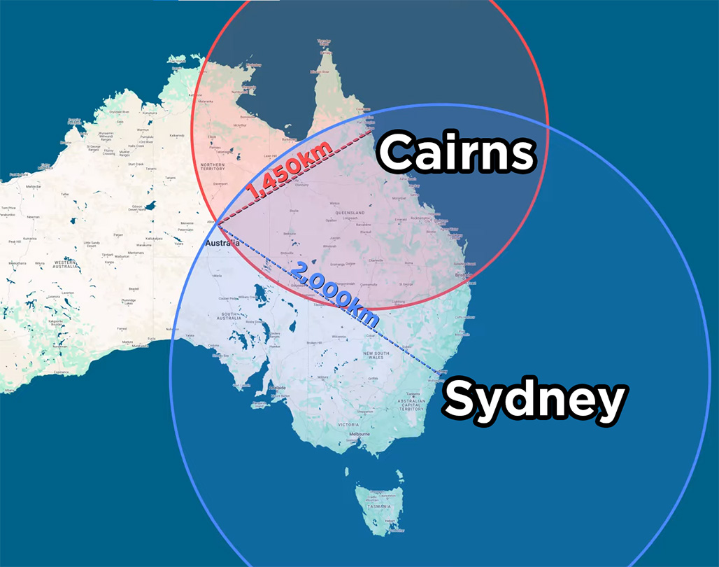
A simplified example of how this locating with distances works: imagine that I was lost somewhere in Australia. But I knew that I was exactly 2,000 km away from Sydney, and I also knew I was exactly 1,450 km away from Cairns. If I drew a 2,000 km circle around Sydney, I know that I could be anywhere on that line. If I drew another circle around Cairns, this time 1,450 km, I could find the place where they both intersect and know that I am in Alice Springs! It gets a bit more complicated in three dimensions, but it's the same idea - if you know how far away the satellites are and where they are, you can find where you are. Remember though, we need 4 satellites for our module to work, not 2 like our cities example!
This process is called trilateration (not triangulation, which is slightly different) and the GPS module we're using handles all this complex math for us, giving us a simple readout of coordinates. And the best part? There is no subscription required for this, and it's a 1-way system as we are just intercepting signals from these satellites - we know where the satellites are, but the satellites have no idea about us!
What You Will Need
To follow along with this guide you will need:
- A Raspberry Pi Pico: Any variant of the Pico will work, but we are using the Pico 2.
- A U-blox NEO-6M GPS Module.
- A Breadboard to house everything.
- Jumper Wires to connect it all.
Connecting and Reading the GPS
First things first, let's connect our GPS to our Pico. Starting off, ensure you have soldered header pins onto your GPS module and Pico, and place them on the breadboard. We will then power it by connecting a ground pin of the Pico to the ground pin of the module, as well as the 3.3-volt pint of the Pico to the Vcc Pin of the Module.
This GPS module can be powered with either 3.3 volts or 5 volts, there is no operational difference, just a handy bit of information.
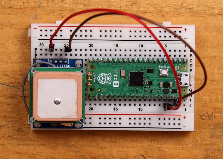
Then connect the TX pin (transmitter pin) of the GPS module to Pin 1 of the Pico which is the RX pin (receiver pin). This is a UART connection and the GPS module is going to transmit data on the TX pin, which we will receive on the RX pin of the Pico.
UART is also a 2-way street meaning that we can send information from the Pico to the GPS module, however, this is unnecessary in our use-case so the connection is not needed. If you wish to make this connection though, connect Pin 0 of the Pico to the GPS's RX pin.

And that is all we need! Let's jump into Thonny and code this up. Now if this is your first time dealing with Thonny and the Pico, or you need a refresher, we have a quick getting started guide which is also a part of an entire comprehensive Pico course if you wanna check that out. Plug in your Pico, select its COM port and paste in the following code which will read and display the raw UART data coming from the GPS module:
from machine import Pin, UART
import time

# Set up UART connection to GPS module
uart = UART(0, baudrate=9600, tx=Pin(0), rx=Pin(1))

# Main loop
while True:
    # Check if data is available from GPS
    if uart.any():
        # Read the available data
        gps_reading = uart.read().decode('utf-8')

        print(gps_reading)
We aren't going to mull over the code very much, but if you want to explore how it works, we have an entire video in our Pico course about UART. Run this code, and you should see the output data of the GPS being printed in the shell. But chances are yours might look like the text below with a lot of commas, and not much information.

This is actually what the GPS outputs when it hasn't gotten a "lock" onto enough satellites yet (it isn't receiving a good enough signal from at least 4 satellites). When writing this I am sitting in our giant metal cage of a warehouse so it's a little difficult to receive those signals, and we aren't able to get our position yet. You can confirm this by seeing a 'V' in the status field in the top line of the message. When your GPS module can see enough satellites and can start finding your location, this will instead be the letter 'A', and the red LED on the module will also start flashing.

It may take your module a few minutes to get a lock if it hasn't been powered on for a while, and if you are like us and inside a giant metal building, you might need to move closer to a window or head outside to get a lock onto those satellites. We found that if we took it outside and powered on the Pico for a few minutes to get a lock, we were able to then work on it inside and it kept that lock.
This also brings up a conversation about accuracy and operating conditions. Essentially, the more that's between you and the satellites in space, the less accurate it will be. When we were outside with a clear view of the sky, the GPS module was accurate to less than a meter. However, when it was really cloudy outside (almost storming), and we were in between a few buildings and under some trees, it was accurate to about 2 or 3 meters. And when we bring it inside the giant metal warehouse, that blows it out to a dozen, sometimes maybe a hundred meters off - it all depends on your conditions. But the more things between you and the satellites that might block signals, the less accurate your GPS will be.
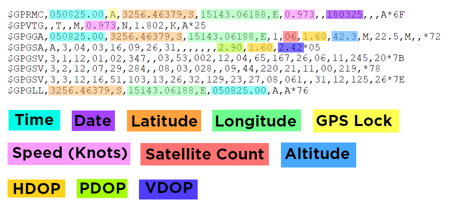
After Going outside and getting a lock, we were able to start receiving a full message as shown on the right, we have also gone ahead and highlighted where the essential information is - this is not mandatory to learn, just a helpful guide if you ever need it. Much of what is not highlighted is information about the satellites that the GPS is receiving from.
All of the information that we want is in there but it's quite hard to use in the format it is in. This format is called the NMEA format and is a standard for GPS outputs. While this is helpful for devices built for this standard, we now have the task of manipulating this string to extract the information we need. This can be quite a difficult task so don't be afraid to turn to an LLM like ChatGPT, Claude or Deep Seek to help you write code for this section as they are quite well-versed with the NMEA format.
Another option is to use a library, and we have already written one for this specific module.
Using a GPS Library
We have written a basic library that greatly simplifies the process of using the module and you can download it here:
Download and unzip the file. Then in Thonny, ensure that you have the file explorer side menu open. You can open this by opening the View tab at the top and ticking Files. On the top window (which is your computer's storage), navigate to the unzipped library, right-click it and upload it to the Pico like in the image on the right.
After uploading you can confirm it is now on your Pico as it should be visible in the lower window (which is your Pico's storage).
This library not only hides a lot of the complexities of extracting the relevant information from the GPS string but also deals with the UART interactions for us as well. The code below is a demo of how to use the library:

from machine import Pin, UART
import time
import gps_parser  # Import our GPS parser library

# Set up UART connection to GPS module
uart = UART(0, baudrate=9600, tx=Pin(0), rx=Pin(1))

# Create a GPS reader object
gps = gps_parser.GPSReader(uart)

# Main loop
while True:
    # Get the GPS data, this will also try and read any new information form the GPS
    gps_data = gps.get_data()

    # Print the GPS data
    print(gps_data.has_fix, gps_data.latitude, gps_data.longitude)

    # Small delay
    time.sleep(0.5)
Paste in this sample code to Thonny, hit run and you should see some more nicely formatted GPS data being printed to the shell, in this case, it is whether the GPS has a lock or not, and its latitude and longitude (which will both be 0 if it doesn't have a lock).
The important commands in this code are the creation of the GPS object using the library, which takes in the UART connection we set up:
# Create a GPS reader object
gps = gps_parser.GPSReader(uart)
And the ".get_data()" command which will tell the library to get the latest reading from the GPS, and extract all the relevant information out of it. In this demo code, the information will be stored in the variable "gps_data". The GPS will only output new data about every second, so if you run this function before the GPS outputs new information, it will just output the last reading. If you try to read the GPS 2 times a second, you will get the same reading twice in a row as it only produces new data every second.
# Get the GPS data, this will also try and read any new information form the GPS
gps_data = gps.get_data()
Now we have the "gps_data" variable which is a structure holding a whole heap of other variables. If we wanted to get time from this structure, we would simply need to use "gps_data.time". In the demo code, we have an example of printing some of these variables:
# Print the GPS data
print(gps_data.has_fix, gps_data.latitude, gps_data.longitude)
If you open the GPS library you can find all the information stored in this structure at the top. Below is what that looks like. Most of these are straight forward but for clarification of the tricky ones; ".satellites" is the number of satellites the GPS is connected to and ".hdop", ".vdop", and ".pdop" are ratings of the horizontal, vertical and overall positional accuracy of the GPS readings. These are called the dilution of precision and essentially the lower the number is, the more accurate it is. Anything under 5 is a good reading.
    def __init__(self):
        self.has_fix = False
        self.latitude = 0.0
        self.longitude = 0.0
        self.speed_knots = 0.0
        self.time = ""
        self.date = ""
        self.satellites = 0
        self.altitude = 0.0
        self.hdop = 0.0  # Horizontal Dilution of Precision
        self.pdop = 0.0  # Position Dilution of Precision
        self.vdop = 0.0  # Vertical Dilution of Precision
An important note here is that this library outputs coordinates in the positive/negative decimal degrees (DD) format. This is different to the raw UART output format the GPS uses which is degrees decimal minutes (DDM) which looks like this:
3256.44393,S,15143.09072,E
There are a lot of different systems of representing coordinates and some are more fit for certain uses than others, but for our projects, the DD format will likely be the best choice. The same GPS reading from the Library will look like this:
-32.94073, 151.71818
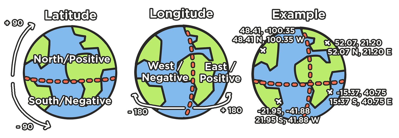
These 2 numbers are not only easier to understand as a person, but also make the math relating to coordinates easier (in a little bit we will be using this math to calculate the distance between coordinates). Below is an image showing this DD coordinate system. Latitude is a measurement of your distance from the equator, and longitude is a measurement of how far away you are from the Prime Meridiam, a single line drawn from the north pole to the south pole cutting through parts of West Africa. This line is also where all timezones are based on, you are currently either a certain amount of hours ahead of this time, or behind it and your GPS will give the time in this zone. This DD system can also use the north/south and east/west format, but this library will use the positive/negative format.
With this library and understanding of it, you are now able to add an accurate reading of location, altitude, and time to your project! Before we finish though, let's take a look at this module in action with a short and sweet project.
Project: Navigate Anywhere in the World
We currently have a Pico that can find our location anywhere on the surface of the planet, and just to show how powerful of a concept that is, we are going to combine it with a few other simple components to build a device that will take a target GPS coordinate and inform us how far away that destination is, and what direction we will need to head. To follow along you will also need a:
- Battery or method of powering the Pico: We love these USB AA battery packs for simplicity (which pair fantastically with rechargeable NIMH batteries).
- SSD1306 OLED: We are using the Piicodev OLED which we assemble in-house, but any generic OLED display will work. If you do use a different display, the connection method will differ a little from this guide as we are using the Piicodev connection system.
- MMC5603 Magnetometer: This is a module that acts like a compass and will allow our Pico to know which direction it is pointing in.
Optionally you may also want to grab the Pico expansion board and Piicodev cables to make wiring this a bit easier. You will also need a method of mounting this all which could be a piece of cardboard or a 3d printed case. In this guide, we will be using this laser-cut platform.
Already knowing how to connect the GPS to the Pico, assembly is straight forward and the image on the right is our version of the final assembly. If you wish to follow along, here is how to assemble it:
First, sit the Pico in its adapter and screw it onto the platform with the included nylon stand-offs and screws.
Then use the stand-offs to mount the GPS to the platform and connect it to the Pico, also ensuring the antenna is securely mounted with something like blu-tack or double-sided tape.
Then mount the screen and and magnetometer with the stand-offs, and connect them to the adapter board with the Piicodev cables. We have a quick guide on making these connections if you need a hand or a refresher.
And finally mount your battery pack to the platform with something like blu-tack, hot glue or double-sided tape.

We are also going to need to download some libraries needed for this project. This process is the same as uploading the GPS library, except these do not need to be unzipped, they are downloaded directly as the library file. Right-click and "save link as" to download them.
- Download the PiicoDev Unified Library: PiicoDev_Unified.py
- Download the device module: PiicoDev_MMC5603.py
- Download the device module: PiicoDev_SSD1306.py
Before using the magnetometer it must first be calibrated which is covered in our magnetometer getting started guide. This process will only need to be done once, and after completion, it will create a calibration data file which is stored on the Pico.
And now we can finally copy and paste the demo code into Thonny:
from machine import Pin, UART
import time
import math
from PiicoDev_SSD1306 import create_PiicoDev_SSD1306
from PiicoDev_MMC5603 import PiicoDev_MMC5603
from PiicoDev_Unified import sleep_ms
import gps_parser

# Set your destination coordinates here (latitude, longitude)
DESTINATION_LAT = -32.940921  # Latitude in decimal degrees
DESTINATION_LON = 151.717916  # Longitude in decimal degrees

# Initialize UART for GPS module
uart = UART(0, baudrate=9600, tx=Pin(0), rx=Pin(1))

# Initialize the GPS reader with our new library
gps = gps_parser.GPSReader(uart)

# Initialize OLED display
display = create_PiicoDev_SSD1306()

# Initialize compass/magnetometer
compass = PiicoDev_MMC5603()

# Variables to store the latest GPS information
latest_distance = 0
latest_bearing = 0

def calculate_distance(lat1, lon1, lat2, lon2):
    """Calculate the great-circle distance between two points on Earth (in meters)"""
    # Convert decimal degrees to radians
    lat1, lon1, lat2, lon2 = map(math.radians, [lat1, lon1, lat2, lon2])

    # Haversine formula
    dlat = lat2 - lat1
    dlon = lon2 - lon1
    a = math.sin(dlat/2)**2 + math.cos(lat1) * math.cos(lat2) * math.sin(dlon/2)**2
    c = 2 * math.asin(math.sqrt(a))
    # Earth radius in meters
    r = 6371000
    distance = c * r
    return distance

def calculate_bearing(lat1, lon1, lat2, lon2):
    """Calculate the initial bearing from point 1 to point 2"""
    # Convert decimal degrees to radians
    lat1, lon1, lat2, lon2 = map(math.radians, [lat1, lon1, lat2, lon2])

    # Calculate the bearing
    dlon = lon2 - lon1
    y = math.sin(dlon) * math.cos(lat2)
    x = math.cos(lat1) * math.sin(lat2) - math.sin(lat1) * math.cos(lat2) * math.cos(dlon)
    initial_bearing = math.atan2(y, x)

    # Convert from radians to degrees
    initial_bearing = math.degrees(initial_bearing)
    bearing = (initial_bearing + 360) % 360
    return bearing

def draw_arrow(angle, center_x, center_y, size):
    """Draw an arrow pointing in the specified angle (in degrees)"""
    # Convert angle to radians
    rad_angle = math.radians(angle)

    # Calculate arrow tip
    tip_x = int(center_x + size * math.sin(rad_angle))
    tip_y = int(center_y - size * math.cos(rad_angle))

    # Calculate base points for arrow
    base_angle_1 = rad_angle + math.radians(150)
    base_angle_2 = rad_angle - math.radians(150)

    base_x1 = int(center_x + (size/2) * math.sin(base_angle_1))
    base_y1 = int(center_y - (size/2) * math.cos(base_angle_1))

    base_x2 = int(center_x + (size/2) * math.sin(base_angle_2))
    base_y2 = int(center_y - (size/2) * math.cos(base_angle_2))

    # Draw the arrow
    display.line(center_x, center_y, tip_x, tip_y, 1)
    display.line(tip_x, tip_y, base_x1, base_y1, 1)
    display.line(tip_x, tip_y, base_x2, base_y2, 1)

# Main loop for display updates
while True:
    # Clear the display
    display.fill(0)

    # Get compass heading
    heading = compass.readHeading()

    # Get current GPS data
    gps_data = gps.get_data()

    # If we have valid GPS data, calculate distance and bearing
    if gps_data.has_fix:
        # Calculate distance to destination
        latest_distance = calculate_distance(gps_data.latitude, gps_data.longitude, DESTINATION_LAT, DESTINATION_LON)

        # Calculate bearing to destination
        latest_bearing = calculate_bearing(gps_data.latitude, gps_data.longitude, DESTINATION_LAT, DESTINATION_LON)

        # Calculate the difference between bearing to destination and current heading
        relative_angle = (latest_bearing - heading) % 360

        # Draw the arrow at the center of the display
        draw_arrow(relative_angle, 30, 26, 26)

        # Show distance
        if latest_distance >= 1000:
            display.text(f"{latest_distance/1000:.1f} km", 0, 57, 1)
        else:
            display.text(f"{latest_distance:.0f} m", 0, 57, 1)

        # Show altitude
        display.text(f"{gps_data.altitude:.1f}", 90, 57, 1)

        # Show current coordinates
        display.text(f"{gps_data.latitude:.6f}", 64, 2, 1)
        display.text(f"{gps_data.longitude:.6f}", 64, 12, 1)

        # Show destination coordinates
        display.text(f"{DESTINATION_LAT:.6f}", 64, 30, 1)
        display.text(f"{DESTINATION_LON:.6f}", 64, 40, 1)

        # Draw the partial octagon around the arrow
        display.line(47, 0, 58, 11, 1)
        display.line(58, 11, 58, 38, 1)
        display.line(58, 38, 47, 49, 1)
        display.line(0, 11, 11, 0, 1)
        display.line(0, 11, 0, 38, 1)
        display.line(0, 38, 11, 49, 1)

        # Draw the partial box around altitude
        display.line(86, 54, 86, 64, 1)
        display.line(86, 54, 128, 54, 1)

        # Draw the line between the current coords and the target
        display.line(70, 24, 128, 24, 1)
    else:
        # No GPS fix - show "Waiting for GPS" and satellite count if available
        display.text("Waiting for GPS", 10, 20, 1)
        display.text("No Fix", 40, 35, 1)

        # Show satellite count
        display.text(f"Satellites: {gps_data.satellites}", 20, 50, 1)

    # Print debug information to the console (optional)
    print(f"Satellites: {gps_data.satellites}, ", end="")
    print(f"Position: {gps_data.latitude}, {gps_data.longitude}, ", end="")
    print(f"Altitude: {gps_data.altitude} m, ", end="")
    print(f"Fix: {'Yes' if gps_data.has_fix else 'No'}")

    # Update the display
    display.show()

    # Update at 10 Hz (1/0.1 seconds = 10 Hz)
    time.sleep(0.1)
Run that code, and you should be greeted by a screen that waits till the GPS has a lock, also displaying how many satellites it is connected to. Once it has a lock, you will see the screen on the right showing you the direction and distance to the target (by default set to the Core Electronics office), as well as your location, altitude and the target's coordinate.
If you want to run this code automatically it is as simple as saving it to the Pico and naming it "main.py". When the Pico is powered on, it will search for a file by this name and automatically start executing the code on it. Once saved you should be able to switch on your battery pack and start navigating without the need for a computer.

And if you want to navigate to somewhere else other than the Core Electronics office (we don't see why you wouldn't want to), you can simply edit the target GPS coordinates at the top of the code:
# Set your destination coordinates here (latitude, longitude)
DESTINATION_LAT = -32.940921  # Latitude in decimal degrees
DESTINATION_LON = 151.717916  # Longitude in decimal degrees
One of the easiest ways to get a target GPS coordinate would be with Google Maps. If you click on any point on earth, it will give you the coordinates of that point in the positive/negative DD format the code uses.
And with that, you now have a device that can navigate you to any location on the surface of the earth, overcoming the need to master a skill that took our ancestors many years to learn. And all of that is thanks to the humble GPS module.

If you made anything cool with this module, or you need a hand with anything we covered here or in the video, feel free to drop post on our forum below, we are all makers here and happy to help!

