Introduction
Welcome to the guide for the Makerverse Essentials Kit. This kit provides the fundamental hardware required to construct many of the kits in the Makerverse Kits range along with providing hardware which will continue to be useful during your electronics adventure.
To follow along you will need:
- The Makerverse Essentials Kit
- A computer capable of running Thonny (a desktop, laptop, or Raspberry Pi)
Kit Contents
Inside the Makerverse Essentials Kit you will find:
- An 830 tie point breadboard
- A tool for quickly building circuits
- A Raspberry Pi Pico with Soldered pin headers
- A programmable microcontroller board
- A Micro USB cable
- A ribbon of 40 male-to-male jumper wires
- An assortment of light emitting diodes (LEDs) with current-limiting resistors
- An assortment of tactile switches with coloured caps
- A Pocket screwdriver
These parts have been chosen for both their immediate applications in the Makerverse Kits range and long term usefullness. Nothing here is "kit specific" - all of these items will continue to be useful beyond the kit experiences.
Breadboard Basics
A breadboard is an electronics tool that allows quick and easy construction of circuits. The included breadboard contains 830 holes for inserting components and has internal terminals which connect holes together into strips.
There are two types of breadboard strips: terminal strips and power rails. The power rails connect along the entire long edges of the breadboard and are typically used to distribute power. The red and black lines indicate a suggested polarity for connecting power and provide a visual cue to avoid connecting power backward or creating short circuits.
Terminal strips are groups of 5 holes connected together and cover the rest of the breadboard. There is a large "ditch" separating the two blocks of terminal strips which indicates that opposite terminal strips are not connected to each other. This allows for devices with two parallel rows of pins to be inserted without opposite pins being connected.

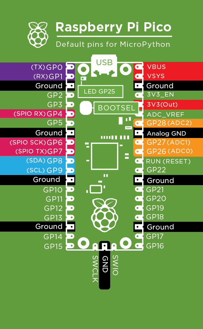
Raspberry Pi Pico
The Raspberry Pi Pico (or just "Pico", for short) will be the "brains" behind most projects. It is a microcontroller board that will be programmed in MicroPython.
At one end you will find a micro USB socket - the included micro USB cable is used for connecting the Pico to a PC for programming.
Connections between the Pico and other project modules are made with the surrounding pins. The pins can be referred to either by their pin number (1, 2, 3, ..., 40) or the pin's function. The adjacent pinout diagram shows the pin functions.
With only a handful of exceptions, the pin functions fall into two broad categories: digital input/output and power. The digital pins are typically referred to as "general purpose" pins and are numbered as GP0, GP1, etc. The general purpose pins can be either inputs or outputs, where an input will "read" as either a logic 0 or 1 depending on the voltage on the pin (0V and 3.3V, respectively) and an output will generate either 0V or 3.3V to "drive" other components.
Most of the digital pins can also be used as special communications ports such as I2C, SPI, or UART. These are all communications standards that some external modules will use.
Lastly, digital pins GP26, GP27, and GP28 (pins 31, 32, and 34) are all connected to Analog to Digital Converters (ADCs) which convert a voltage on the pin to a number that can be used by the program.
The power pins will be used to supply power to external modules. There are 8 "ground" (GND) pins - these are the 0V or "negative" pins, a 3.3V source (pin 36: 3V3(OUT) ) and a 5V source (pin 40 - VBUS). The VSYS pin is typically used to supply external power into the Pico and is protected by a diode so that external power won't flow into the USB cable if it is connected.
Getting Started with Thonny
Thonny is a simple integrated development environment (IDE) designed for developing code in Python. It includes MicroPython support for several popular microcontroller development boards in addition to including a Python interpreter for desktop computer use.
If you're using a Raspberry Pi then Thonny should already be installed. Otherwise, head over to thonny.org and download the installation file for your operating system. There are installation notes for Windows, MacOSX, and Linux.
Once installed, follow these steps to get started programming the Raspberry Pi Pico:
- If your Raspberry Pi Pico is brand new, plug it into a USB port while holding the BOOTSEL button. It will appear as a "USB mass storage" device (ie: a USB flash stick). This is the so-called "bootloader" mode and allows for MicroPython to be uploaded.

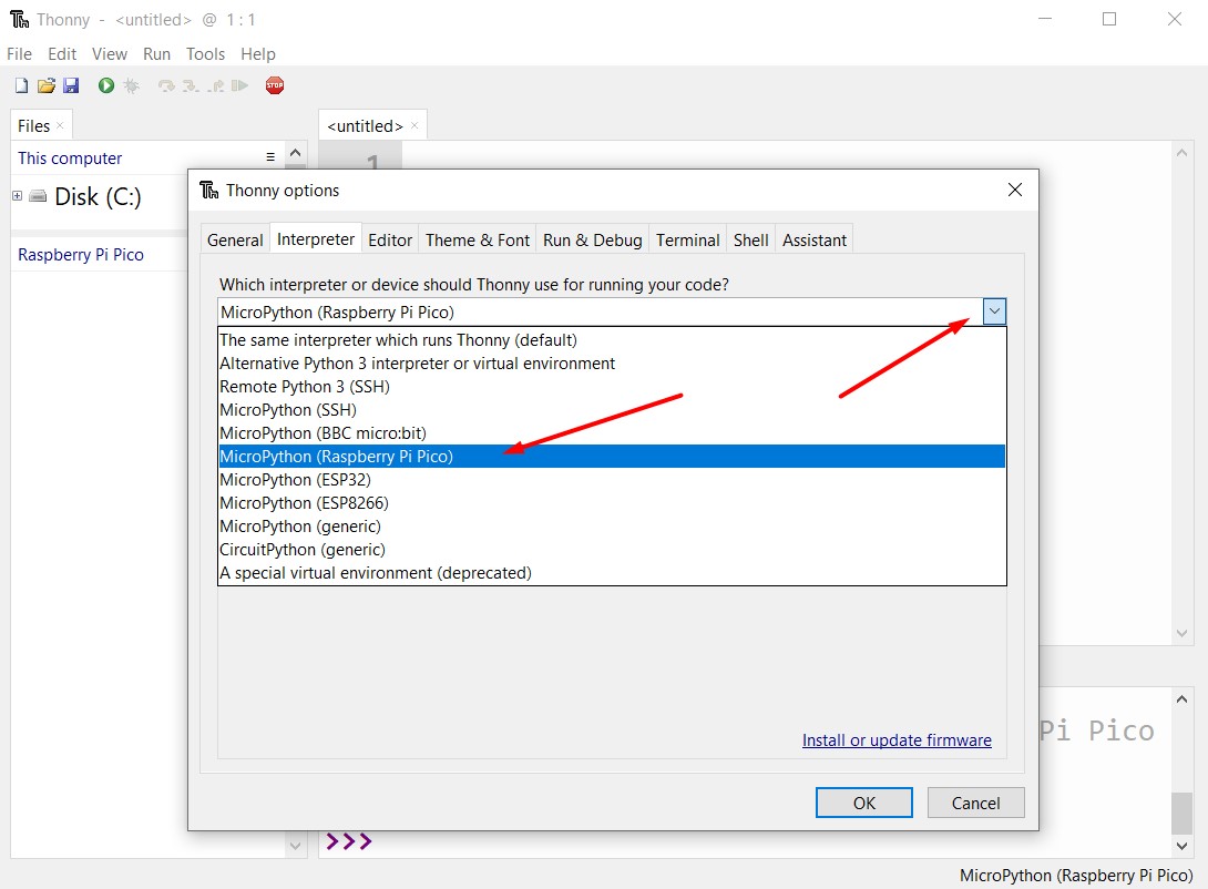
- Open Thonny and set the Python interpreter to the Raspberry Pi Pico. The setting is found under Run > "Select Interpreter..." followed by selecting "MicroPython (Raspberry Pi Pico)" from the top drop-down menu.
- With the Pico selected as the MicroPython interpreter, Thonny will attempt to find a connected Pico and communicate with the MicroPython firmware. If your Pico is brand new it will need MicroPython installed. This can be done by clicking "Install or update firmware" in the lower right. This will bring up the "Install MicroPython firmware for Raspberry Pi Pico" dialog box. Click "Install" to copy across the MicroPython firmware.
- Once complete, the dialog boxes can be closed and you should be presented with the MicroPython prompt in the Shell.
- You can test the MicroPython shell by typing in any MicroPython command and pressing Enter. It is recommended, however, that scripts are saved to the Pico because debugging and editing in the command prompt is tedious and nothing is saved!
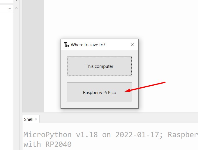
To create a simple test script type "print("hello")" into the editor then press ctrl+r to tell Thonny to run the code. You will be prompted with the option to save the script to your PC or to the Pico, so click "Raspberry Pi Pico". - A save dialog box will appear. For this guide we will save the script as "example.py":
- Once saved you should see the file listed on the left side "Files" tab along with the output from the program in the Shell. If the file list isn't visible you can enable it with View > Files. In the Shell you should see "hello" printed - this is the output from running the script.


MicroPython Programming Examples
Example: Turning on the onboard LED. The Raspberry Pi Pico has a small light emitting diode (LED) connected to pin GP25. This pin isn't connected to an external pin so it can only be used to control the onboard LED.
Copy the code below into the Thonny editor, press ctrl+r to run it, and, if you haven't yet done so, save it to the Pico as example.py. It will take about half a second to run and you will notice that the onboard LED turns on and the shell presents the >>> command prompt to indicate that the code has finished executing.
# This example turns an LED on!
from machine import Pin # The "Pin" module is used to control GPIO
led = Pin(25, Pin.OUT)  # configure GP25 (the built-in LED) as an output
led.on()
After the code has finished the LED "object" will still exist. To turn the LED off you can type LED.off() in the shell.
Example: Blinking the onboard LED. This example uses a while True: "loop". This is code that will continue executing the same code forever.
Furthermore, it uses the sleep_ms() method from the time library. This method provides a delay with millisecond resolution.
from machine import Pin
from time import sleep_ms # sleep_ms is used to create a delay

LED = Pin(25, Pin.OUT)

while True:       # Loop forever
    LED.on()      # Turn the pin on
    sleep_ms(500) # wait half a second
    LED.off()     # Turn the pin off
    sleep_ms(500) # wait half a second

Automatic Execution with main.py
If a script is saved as main.py it will have special behaviour: it will start executing when the Pico is powered-on. This is how a project can be deployed without being plugged into a computer.
Take the blinking LED code from the previous section click File > Save As... and save it to the Pico as main.py.
Unplugging the Pico then plugging it back in should result in the onboard LED blinking without Thonny being connected. Note disconnecting the Pico will cause Thonny to produce an error; click the "Stop / Restart backend" icon (or press ctrl+F2) to reconnect to the Pico and stop main.py from executing.
Using Light Emitting Diodes (LEDs)
Light emitting diodes (LEDs) are electronic components which emit light when current is passed through them. This kit includes five LEDs of different colours, along with five current-limiting resistors. These devices will typically be used as indicators and driven by digital output ports from the Raspberry Pi Pico.
All LEDs are polarised: current will only pass through them in one direction. The longer pin (known as the "anode") is the positive pin while the shorter ("cathode") pin is the negative. All Makerverse kit LED applications will require them to be wired with the positive pin "pointing towards" the Pico and negative pin pointing towards ground.
The included resistors must be connected in series with the LED. Without them, the LED or Pico can be damaged due to high current flow. The resistor can go before or after the LED.
The example code below is the classic "blinky" example from above moved to GP15. Connect the LED as shown for an external LED blink example in the colour of your choice.
# A simple example to blink an LED forever

from machine import Pin
from time import sleep_ms

LED = Pin(15, Pin.OUT) # Set GP15 as an output

while True:
    LED.on()
    sleep_ms(500)
    LED.off()
    sleep_ms(500)

Using Tactile Switches
Tactile switches (or, less formally, buttons) are the simplest form of human input, allowing for the generation of true/false digital signals from finger presses.
Physically, tactile switches are either an "open circuit" (current is blocked from flowing) or a "short circuit" (current flows with insignificant loss). The included tactile switches are "normally open" types - they are an open circuit when not pushed and a short circuit when pushed.
Makerverse kits will typically connect one side of the switch to 3.3V (pin 36 of the Pico) and the other to a digital input pin. The pin will then be configured with a so-called "internal pull-down" so that it reads a logic 0 when not pushed and a logic 1 when pushed.
Note that the buttons have four pins, with two pairs of pins on opposite sides. They are inserted into the breadboard with the two pairs of pins "bridging" the central ditch. In this orientation pressing the button connects the top two pins to the bottom two.

Example: Printing the value of a switch pin.
from machine import Pin
from time import sleep_ms

button = Pin(16, Pin.IN, Pin.PULL_DOWN)

while True:
    buttonPressed = button.value()   # Read the GP16's logic state as 1 (ON) or 0 (OFF)
    print(buttonPressed)
    sleep_ms(100)

Controlling LEDs with Buttons
Finally, lets combine our knowledge of LEDs and buttons to allow a blinking LED to be controlled by a button. The code below uses the LED and button objects from earlier, along with a "while True:" infinite loop, and adds an if-else block so that the LED only blinks if the button is pressed.
from machine import Pin
from time import sleep_ms

LED = Pin(15, Pin.OUT)
button = Pin(16, Pin.IN, Pin.PULL_DOWN)

while True:
    if button.value() == 1:    # The code "inside" the if only runs if button.value() is 1.
        LED.on()
        sleep_ms(100)
        LED.off()
        sleep_ms(100)
    else:                      # Code below "else" runs if button.value() was NOT 1.
        LED.off()
Conclusion
Now that we've covered how to use the parts supplied with the Essentials kit you are well equipped to dive into the other Makerverse Kits and the broader world of hobby electronics!
If you make something cool from this starter guide we'd love for you to share it on our forums! And if you'd like some help with this guide, start the conversation below - We're full-time makers and here to help!
