In this guide, we will be exploring ultra-wideband modules and how you can use them to add robust distance measurements to your next maker project. We'll be learning how these incredible little boards work, what you can expect from them, and how to configure and connect them to your microcontroller to get distance measurement readouts. This guide is going to be looking specifically at the BU03 boards as they are one of the cheapest entry points for this technology, and we will have MicroPython examples for a board like the Raspberry Pi Pico, and C++ examples for boards like an Arduino or ESP32.
Let's get into it!
What is Ultra-Wideband and how Does it Work?
Ultra-wideband (UWB) has been around for a while, but only in the last few years has it really taken off and seen widespread adoption. UWB is cropping up in many places and is now able to be found onboard many flagship smartphones. Even Apple's Airtag system partially uses UWB so you may be using this system without even realising it!
At its core UWB is a low-power, short-range, high-bandwidth (meaning it can transmit a lot of data) radio communication technology that spreads its communication across a wide band in the radio spectrum - about 500 Mhz. This makes it suitable for a growing number of use cases such as data transfer, radar imaging and distance ranging/locating. This last use case is the most rapidly growing and is what we will be looking at in this guide.
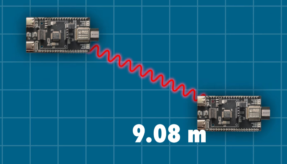
The ultra-wideband board we will be looking at is the AI Thinker UB03, and when we first started playing around with these boards, it made UWB technology seem like magic. We set up two boards and it gave us a reasonably accurate distance reading between the boards' antennae. Now you might be thinking that you could achieve something similar with a laser or ultrasonic distance sensor. But the magic lies in the fact that we didn't have to orientate the boards in a certain way, you can rotate them all you like and it still reads accurately. It also lies in the fact that it can ignore obstacles to a certain degree; a human or piece of furniture in the way didn't interfere.
Where it kicks up a notch is that you can have a small network of these all working together to get distance measurements between multiple boards. That suddenly opens up the possibility of adding 3d spatial tracking to your projects, allowing you to locate something anywhere in a room like a DIY indoor GPS. If this isn't activating your maker neurons, we don't know what will!
UWB distancing has also finally reached the point that is affordable and accessible for maker-tier projects at home. At the time of writing this guide, the BU03 board is one of the cheapest available ways to add it to your project.
But how do these boards work? These boards can operate in a few different ways, but we will be using a time-of-flight method. One board initiates this process by sending a message (in frequencies somewhere between 6.25 and 8.25 GHz). Then the other board that we are measuring the distance to receives this message, and repeats it back. The first board then uses the time it took that signal to return to figure out how far apart they are.
But that message is travelling at the speed of light. If these boards are 30cm or a foot apart, it takes only a billionth of a second to move from point A to point B, so there are some crazy precise clocks onboard these things for that required timing. That is also a simple overview of how it works - there is a whole heap of advanced signal processing going on at mind-boggling speeds to make this system work, and fortunately, we can treat it like that - a black box that just works.

What You Will Need
To follow along with this guide, you will need a:
- BU03 ultra-wideband board. You will need at least 2 to get started and as we will explore in the guide, this system will support up to 9 boards.
- Method of powering the BU03 boards. This guide series may have you powering boards in weird and hard-to-reach places. The easiest way to power these boards is through USB-C which can be plugged into your computer or something like a phone wall charger or a phone power bank (a USB-C Raspberry Pi power supply will also work if you have some around). Longer USB-C cables can be a great help here. There is also an option to power it via GPIO with either 5 V or 3.3 V. If you are using a phone power bank just be aware that some of them have power-saving modes that switch off USB power if not enough current is drawn. These boards will likely not draw enough to keep them from going into this power-saving mode, so test your power bank before committing to multiple of them.
- Microcontroller to read and process the distance data. This guide will have code snippets for both MicroPython and C++. We will be using a Raspberry Pi Pico 2 as our MicroPython example board and an Arduino Uno R4 as our example C++ board. This guide can be adapted to work on most microcontroller boards that have dedicated UART hardware like an ESP32. Please note that the Arduino Uno R3 and older Uno boards are not suitable for this guide as they share their UART hardware with the USB serial port - you won't be able to read the UWB data and print it to your computer at the same time.
- Method of prototyping this all together. A breadboard and some jumper wires will suffice.
Configuring the Boards and AT Commands
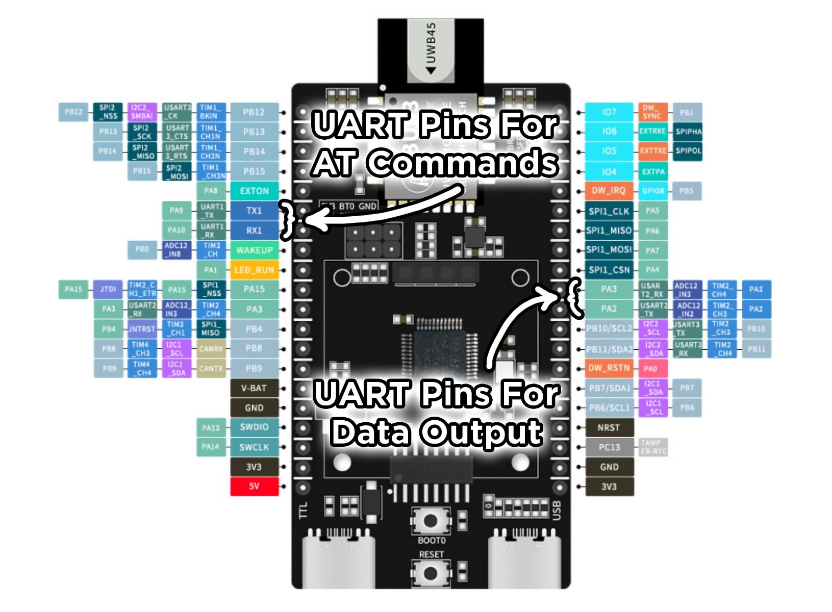
Now that we have our hardware sorted, it's time to configure our UB03 boards. These boards actually have 2 UART channels - one for sending AT commands (which is used for configuration), and another for data output (this is where we will get all of our distance data). There are 2 USB ports and 2 sets of TX and RX pins to access these channels, which can be a bit confusing at first but makes sense once you understand the system.
For configuration, we're going to use our microcontroller to send AT commands to the boards. Let's start by connecting the TX and RX pins of the configuration UART to the microcontroller. These will be labelled as TX1 and RX1 on the underside of the BU03 board.
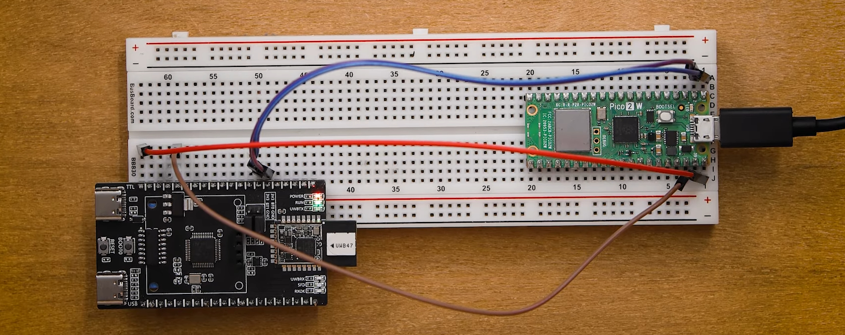
You can connect these to any UART peripheral on your microcontroller. We are using pins 0 and 1 on the Pico for this example, if you use other pins you will need to alter your code accordingly. We will also need to supply power to the board which can be done through GND and any of the 3.3 V and 5 V pins. The image below shows the board fully connected.
Unfortunately, this board is a tad too wide to fit on a standard breadboard. We are making do and hanging it off one side like in the image as it makes it easy to swap out boards if you are configuring a number of them.
We are going to be using Thonny IDE to program our Pico. Plug the Pico into a PC, open up Thonny, and paste in the following configuration code:
from machine import UART, Pin
import time

# Initialize UART 0 on Pico, TX pin is GP0 and RX pin is GP1
uart = UART(0, baudrate=115200, tx=Pin(0), rx=Pin(1))

uart.write('AT+SETCFG=0,0,1,1\r\n')

time.sleep(1)

if uart.any():
    message = uart.read()
    print(message)

time.sleep(3)

uart.write('AT+SAVE\r\n')

time.sleep(3)

if uart.any():
    message = uart.read()
    print(message)


uart.write('AT+GETCFG\r\n')

time.sleep(0.1)

if uart.any():
    message = uart.read()
    print(message)
Configuring the board is straightforward and primarily relies on the "AT+SETCFG=1,1,1,1" command. This command has 4 options which configure the behaviour of the board. Here is a rundown of them in order:
- Board ID (0 to 7): This first number is the ID number that will be assigned to that board and is vitally important when reading distances. Each board in your network has to have a unique ID (except for the tag which we will look at next). If two boards share an ID, you will get conflicting data and incorrect readings. Distance measurements are only output from a board with an ID of 0. If you plug your pico into a board with an ID of 1 or 3 or 6, nothing will come out. Only boards with an ID of 0 will output distance data.
- Board Mode (0 or 1): The second number sets up the board to either be a tag or a base station. 0 is for a tag, 1 is for a base station. The tag can be thought of as the device that will be tracked in a system, and the base stations are what track it. The data output from the system will be the distance from the tag to each base station. At a minimum, you need one tag and one base station to measure distance. If you add a second base station, you will get the distance from the tag to the second base station. You cannot get the distance between base stations. The tag must have an ID of 0 and there can only be one tag. You can have up to eight base stations in a system with IDs from 0 to 7.
- Operating Channel (0 or 1): The third number dictates the frequency on which the board will operate. If set to 0, the board will operate in the range of 7.75 GHz to 8.25 GHz and if set to 1, the board will operate in the 6.25 GHz to 6.75 GHz range. After some brief testing, we found that the lower frequency gave better performance by setting this value to 1. All boards must share the same frequency to work together.
- Data Rate: (0 or 1): This final number dictates the data rate which these boards communicate at. A value of 0 means they will communicate at 850 Kbps, and a value of 1 sets the data rate to 6.8 Mbps. We found very little difference between these values and decided to leave this value at 1. Like frequency, all boards must share the same data rate.
Let's start by setting up a tag. We will set the ID to 0, the mode to 0, and keep the channel and data rate to 1. The line should look like this:
uart.write('AT+SETCFG=0,0,1,1\r\n')
Run the code and it will send that config command, followed by a save command and then a final command which asks the board for its current configuration so we can check it was successful.
After running the code, you should see the confirmation in the shell like in the image on the right.

Now let's set up our first base station! Unplug your tag and plug in the board you wish to use as base station 0. It is a very smart idea to label the boards with their ID and role as you configure them. With the board plugged in, alter the config line to have an ID of 0, a mode of 1 (base station), and a channel and data rate of 1 - ensure all of these boards share the same channel and data rate. Your line should look like this:
uart.write('AT+SETCFG=0,1,1,1\r\n')
Run the code, confirm the settings in the shell, and you now have base station 0! You can set up more base stations by increasing the ID number. If you wanted to set up a second base station (which we would call base station 1), you would use the following line:
uart.write('AT+SETCFG=1,1,1,1\r\n')
And a third base station (which we would call base station 2), would use the following line:
uart.write('AT+SETCFG=2,1,1,1\r\n')
This pattern would repeat up to the 8 maximum base stations we can use and we would call the last one base station 7 as it would have an ID of 7.
Before we move on, there is one more thing that we might use AT commands for, and that is to read the 3-axis accelerometer that these boards have. You can access this data by sending the following command:
uart.write('AT+GETSENSOR\r\n')
This will return acceleration data in X,Y,Z as well as an estimated angle the board is tilted at. We aren't gonna be using this in this guide, but it's just a handy thing to know if your project calls for it. With our boards configured, we are ready to get the all-important distance data, which is going to come out of the 2nd UART channel. AT commands will not work on this 2nd channel - it only outputs distance data, so ensure you have sorted all your configurations before moving on.
Now that we have our hardware sorted, it's time to configure our UB03 boards. These boards actually have 2 UART channels - one for sending AT commands (which is used for configuration), and another for data output (this is where we will get all of our distance data). There are 2 USB ports and 2 sets of TX and RX pins to access these channels, which can be a bit confusing at first but makes sense once you understand the system.
For configuration, we're going to use our microcontroller to send AT commands to the boards. Let's start by connecting the TX and RX pins of the configuration UART to the microcontroller. These will be labelled as TX1 and RX1 on the underside of the BU03 board.
You can connect these to any UART peripheral on your microcontroller. We are using pins 0 and 1 on the Arduino for this example, if you use other pins you will need to alter your code accordingly. We will also need to supply power to the board which can be done through GND and any of the 3.3 V and 5 V pins. The image below shows the board fully connected.
Unfortunately, this board is a tad too wide to fit on a standard breadboard. We are making do and hanging it off one side like in the image as it makes it easy to swap out boards if you are configuring a number of them.

We are going to be using Arduino IDE to program our Pico. Plug the Pico into a PC, open up the IDE, and paste in the following configuration code:
void setup() {
  // Initialize USB Serial for debugging
  Serial.begin(115200);
  while (!Serial) {
    ; // Wait for USB serial port to connect
  }
  Serial.println("Starting board configuration...");

  // Initialize hardware UART on pins 0 (RX) and 1 (TX) for UWB communication
  Serial1.begin(115200);

  delay(2000); // Give some time for everything to get ready

  // Send configuration command
  Serial.println("Sending AT+SETCFG command...");
  Serial1.print("AT+SETCFG=0,0,1,1\r\n");
  delay(1000);

  // Check for response
  if (Serial1.available()) {
    String response = Serial1.readString();
    Serial.println(response);
  }

  delay(3000);

  // Save configuration
  Serial.println("Sending AT+SAVE command...");
  Serial1.print("AT+SAVE\r\n");
  delay(3000);

  // Check for response
  if (Serial1.available()) {
    String response = Serial1.readString();
    Serial.println(response);
  }

  // Get current configuration to verify
  Serial.println("Sending AT+GETCFG command...");
  Serial1.print("AT+GETCFG\r\n");
  delay(100);

  // Check for response
  if (Serial1.available()) {
    String response = Serial1.readString();
    Serial.println(response);
  }

}

void loop() {
}
Configuring the board is straightforward and primarily relies on the "AT+SETCFG=1,1,1,1" command. This command has 4 options which configure the behaviour of the board. Here is a rundown of them in order:
- Board ID (0 to 7): This first number is the ID number that will be assigned to that board and is vitally important when reading distances. Each board in your network has to have a unique ID (except for the tag which we will look at next). If two boards share an ID, you will get conflicting data and incorrect readings. Distance measurements are only output from a board with an ID of 0. If you plug your pico into a board with an ID of 1 or 3 or 6, nothing will come out. Only boards with an ID of 0 will output distance data.
- Board Mode (0 or 1): The second number sets up the board to either be a tag or a base station. 0 is for a tag, 1 is for a base station. The tag can be thought of as the device that will be tracked in a system, and the base stations are what track it. The data output from the system will be the distance from the tag to each base station. At a minimum, you need one tag and one base station to measure distance. If you add a second base station, you will get the distance from the tag to the second base station. You cannot get the distance between base stations. The tag must have an ID of 0 and there can only be one tag. You can have up to eight base stations in a system with IDs from 0 to 7.
- Operating Channel (0 or 1): The third number dictates the frequency on which the board will operate. If set to 0, the board will operate in the range of 7.75 GHz to 8.25 GHz and if set to 1, the board will operate in the 6.25 GHz to 6.75 GHz range. After some brief testing, we found that the lower frequency gave better performance by setting this value to 1. All boards must share the same frequency to work together.
- Data Rate: (0 or 1): This final number dictates the data rate which these boards communicate at. A value of 0 means they will communicate at 850 Kbps, and a value of 1 sets the data rate to 6.8 Mbps. We found very little difference between these values and decided to leave this value at 1. Like frequency, all boards must share the same data rate.
Let's start by setting up a tag. We will set the ID to 0, the mode to 0, and keep the channel and data rate to 1. The line should look like this:
Serial1.print("AT+SETCFG=0,0,1,1\r\n");
Upload the code to the board and it will send that config command, followed by a save command and then a final command which asks the board for its current configuration so we can check it was successful.
After running the code, you should see the confirmation in the serial monitor like in the image on the right.

Now let's set up our first base station! Unplug your tag and plug in the board you wish to use as base station 0. It is a very smart idea to label the boards with their ID and role as you configure them. With the board plugged in, alter the config line to have an ID of 0, a mode of 1 (base station), and a channel and data rate of 1 - ensure all of these boards share the same channel and data rate. Your line should look like this:
Serial1.print("AT+SETCFG=0,1,1,1\r\n");
Run the code, confirm the settings in the serial monitor, and you now have base station 0! You can set up more base stations by increasing the ID number. If you wanted to set up a second base station (which we would call base station 1), you would use the following line:
Serial1.print("AT+SETCFG=1,1,1,1\r\n");
And a third base station (which we would call base station 2), would use the following line:
Serial1.print("AT+SETCFG=2,1,1,1\r\n");
This pattern would repeat up to the 8 maximum base stations we can use and we would call the last one base station 7 as it would have an ID of 7.
Before we move on, there is one more thing that we might use AT commands for, and that is to read the 3-axis accelerometer that these boards have. You can access this data by sending the following command:
Serial1.print("AT+GETSENSOR\r\n");
This will return acceleration data in X,Y,Z as well as an estimated angle the board is tilted at. We aren't gonna be using this in this guide, but it's just a handy thing to know if your project calls for it. With our boards configured, we are ready to get the all-important distance data, which is going to come out of the 2nd UART channel. AT commands will not work on this 2nd channel - it only outputs distance data, so ensure you have sorted all your configurations before moving on.
Reading Distances
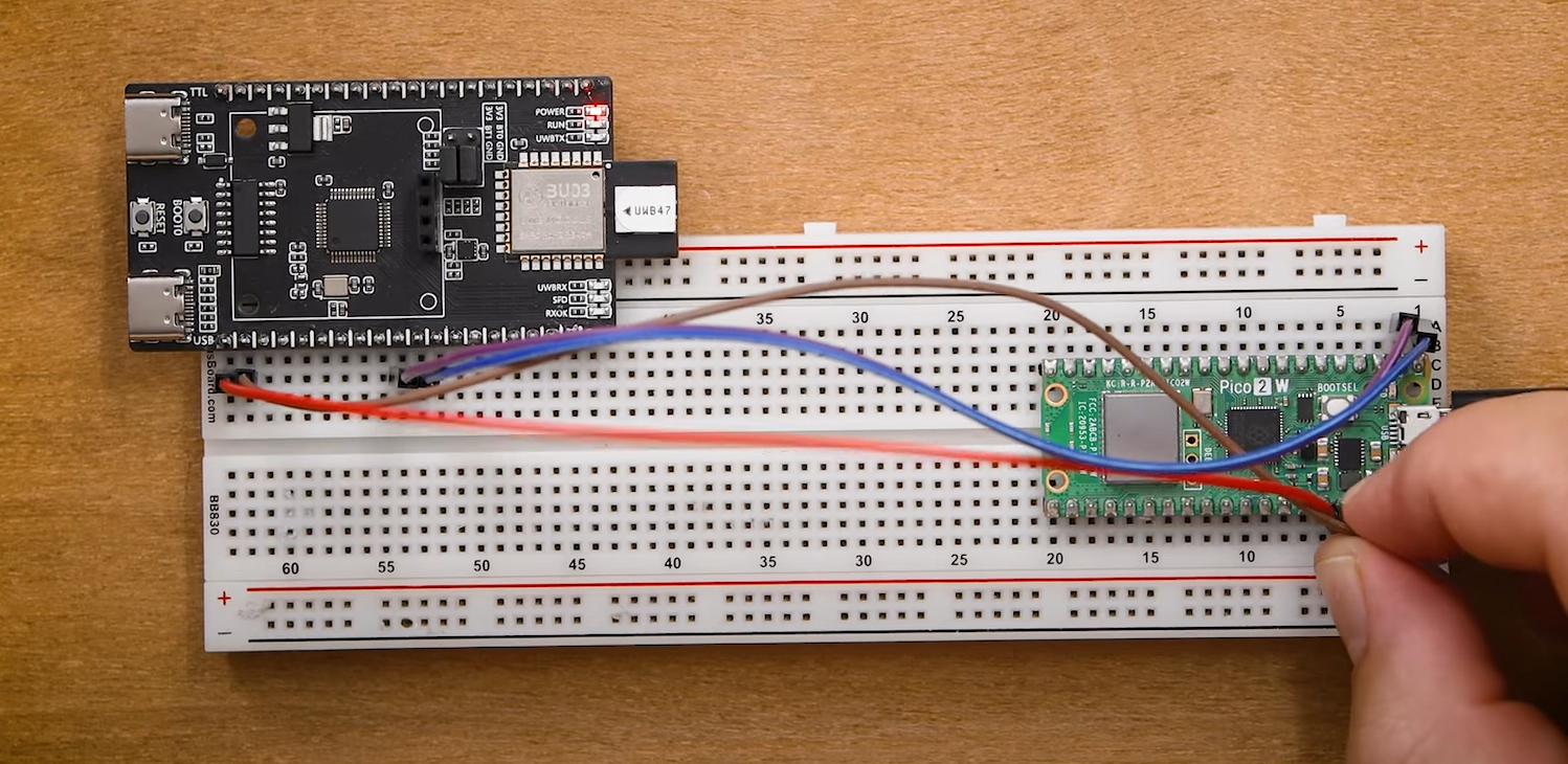
Let's now take a look at how to get the distances between each base station and the tag. To start, we will need to plug our microcontroller into that second UART channel which is going to be accessible through the pins labelled PA2 and PA3 on the underside. PA2 is the TX pin and PA3 is the RX - why are they not labelled like this on the board? No idea. As always ensure you supply power to the board through any of the 3.3 V or 5 V pins. The image on the right shows our complete setup.
After connecting base station 0 to the Pico's UART (we are using pins 0 and 1 again), plug it in and optionally run the following code which is going to print out the raw data coming from the board:
from machine import UART, Pin

uart = UART(0, baudrate=115200, tx=Pin(0), rx=Pin(1))

while True:
    # Check if anything is available in buffer
    if uart.any():
        # recieve and store the message in a variable
        message = uart.read() # this .decode() removes the byte string format
        print(message)
Once this is running, power on the tag either through the GPIO pins or by plugging in a USB-C cable. Once a board is configured, we no longer need a microcontroller to operate it. The board will take a couple of seconds to power on, then it should automatically connect to the base station and finally, both will show 2 flashing blue lights to let us know they have connected. Once they are connected, you should see an output like this in the shell:

This is a pretty stock standard UART message, with a header at the front, and a tail at the end, with the distance data in the middle. This distance data is in a format called 16-bit little-endian and every 4 bytes is going to be a distance measurement in millimetres. This string holds the information for up to 8 distances (the tag to each of our base stations), and if a base station is not detected on the network, it will be left as zeroes. Base stations 4 and 5 are unplugged in the image above, so there you will see some "\x00\" characters where they should be.
What? Are you unable to read 16-bit little-endian format in its raw format? Well lucky for you here is a script that parses this data to make it human readable:
from machine import UART, Pin
import struct
import time

uart = UART(0, baudrate=115200, tx=Pin(0), rx=Pin(1))

def decode_uwb_distances(data):
    """
    Decode UWB distance data from binary message
    Returns list of distances in meters for each base station
    """
    if len(data) < 35:  # Minimum expected length
        return None

    # Check for header pattern
    if data[0:3] != b'\xaa%\x01':
        return None

    # Extract distance data (skip header, process 4-byte chunks)
    distances = []

    # Starting from byte 3, read 4-byte chunks for each base station
    for i in range(8):  # 8 base stations (0-7)
        byte_offset = 3 + (i * 4)  # Each distance is 4 bytes
        if byte_offset + 3 < len(data):
            # Read as little-endian 32-bit integer
            distance_raw = struct.unpack('<I', data[byte_offset:byte_offset+4])[0]
            # Convert to meters
            if distance_raw > 0:
                distance_meters = distance_raw / 1000.0
                distances.append(distance_meters)
            else:
                distances.append(None)  # No signal/not visible
        else:
            distances.append(None)  # Base station not in data

    return distances

def print_distances(distances):
    """Print distances in a readable format"""
    if distances is None:
        print("Invalid data received")
        return

    print("Base Station Distances:")
    for i, distance in enumerate(distances):
        if distance is not None and distance > 0:
            print(f"  BS{i}: {distance:.3f}m")
        else:
            print(f"  BS{i}: Not visible")
    print("-" * 30)

while True:
    # Check if anything is available in buffer
    if uart.any():
        # Receive and store the message in a variable
        message = uart.read()
        print(f"Raw data: {message}")

        # Decode distances
        distances = decode_uwb_distances(message)
        print_distances(distances)
Run that code and you should see an output like the image on the right. Move your tag around and observe the change in your distances. It might help to have a mobile source of power for the tag to help with testing.
If you unplug a base station and plug it back in, it will automatically reconnect to your network. This highlights one of the incredible things about these boards - they just work. This is some pretty complex hardware we are using here and we had nine of these boards all seamlessly working together without a hitch. The only issue we encountered was a rare instance that a board couldn't connect to the network (no flashing blue lights), but turning it off and on again always fixed this. Once everything was connected, we were able to run it for hours without skipping a beat.
And with this, you now have the knowledge and demo code to apply ultra-wideband in your projects!

Let's now take a look at how to get the distances between each base station and the tag. To start, we will need to plug our microcontroller into that second UART channel which is going to be accessible through the pins labelled PA2 and PA3 on the underside. PA2 is the TX pin and PA3 is the RX - why are they not labelled like this on the board? No idea. As always ensure you supply power to the board through any of the 3.3 V or 5 V pins. The image on the right shows our complete setup.
After connecting base station 0 to the Arduino's UART (we are using pins 0 and 1 again), plug it in and optionally run the following code which is going to print out the raw data coming from the board:

const int BUFFER_SIZE = 256;
uint8_t buffer[BUFFER_SIZE];
int bufferIndex = 0;
unsigned long lastByteTime = 0;
const unsigned long messageTimeout = 10; // milliseconds timeout between messages

void setup() {
  Serial.begin(115200);
  Serial1.begin(115200);
}

void loop() {
  // If bytes are available on UART:
  while (Serial1.available()) {
    uint8_t incomingByte = Serial1.read();
    if (bufferIndex < BUFFER_SIZE) {
      buffer[bufferIndex++] = incomingByte;
    }
    lastByteTime = millis(); // Reset timeout whenever we get a byte
  }

  // Check for timeout between messages
  if (bufferIndex > 0 && (millis() - lastByteTime > messageTimeout)) {
    // timeout occurred, assume message ended, print message:
    for (int i = 0; i < bufferIndex; i++) {
      Serial.print("0x");
      if (buffer[i] < 16) Serial.print("0");
      Serial.print(buffer[i], HEX);
      Serial.print(" ");
    }
    Serial.println(); // new line for next message
    bufferIndex = 0; // clear buffer
  }
}
While this is running, power on the tag either through the GPIO pins or by plugging in a USB-C cable. Once a board is configured, we no longer need a microcontroller to operate it. The board will take a couple of seconds to power on, then it should automatically connect to the base station and finally, both will show 2 flashing blue lights to let us know they have connected. Once they are connected, you should see an output like this in the serial monitor:

This is a pretty stock standard UART message, with a header at the front, and a tail at the end, with the distance data in the middle. This distance data is in a format called 16-bit little-endian and every 4 bytes is a distance measurement in millimetres. This string holds the information for up to 8 distances (the tag to each of our base stations), and if a base station is not detected on the network, it will be left as zeroes. Base stations 4 and 5 are unplugged in the image above, so there you will see a field of "0x00" characters where they should be.
What? Are you unable to read 16-bit little-endian format in its raw format? Well lucky for you here is a script that parses this data to make it human readable:
void setup() {
  Serial.begin(115200);
  Serial1.begin(115200);
}

bool decodeUwbDistances(uint8_t* data, int dataLen, float* distances) {
  // Initialize all distances to -1 (equivalent to None)
  for (int i = 0; i < 8; i++) {
    distances[i] = -1.0;
  }

  if (dataLen < 35) {
    return false;
  }

  // Check for header pattern
  if (data[0] != 0xaa || data[1] != 0x25 || data[2] != 0x01) {
    return false;
  }

  // Extract distance data (skip header, process 4-byte chunks)
  for (int i = 0; i < 8; i++) {  // 8 base stations (0-7)
    int byteOffset = 3 + (i * 4);  // Each distance is 4 bytes
    if (byteOffset + 3 < dataLen) {
      // Read as little-endian 32-bit integer
      uint32_t distanceRaw = data[byteOffset] |
                            (data[byteOffset + 1] << 8) |
                            (data[byteOffset + 2] << 16) |
                            (data[byteOffset + 3] << 24);

      // Convert to meters
      if (distanceRaw > 0) {
        distances[i] = distanceRaw / 1000.0;
      } else {
        distances[i] = -1.0;  // No signal/not visible
      }
    }
  }

  return true;
}

void printDistances(float* distances, bool validData) {
  if (!validData) {
    Serial.println("Invalid data received");
    return;
  }

  Serial.println("Base Station Distances:");
  for (int i = 0; i < 8; i++) {
    if (distances[i] > 0) {
      Serial.print("  BS");
      Serial.print(i);
      Serial.print(": ");
      Serial.print(distances[i], 3);
      Serial.println("m");
    } else {
      Serial.print("  BS");
      Serial.print(i);
      Serial.println(": Not visible");
    }
  }
  Serial.println("------------------------------");
}

void loop() {
  static uint8_t buffer[256];
  static int bufferIndex = 0;
  static bool messageStarted = false;

  // Check if anything is available in buffer
  while (Serial1.available()) {
    uint8_t incomingByte = Serial1.read();

    // Look for start of message
    if (!messageStarted && incomingByte == 0xAA) {
      messageStarted = true;
      bufferIndex = 0;
      buffer[bufferIndex++] = incomingByte;
    } else if (messageStarted) {
      buffer[bufferIndex++] = incomingByte;

      // Check if we have a complete message (35+ bytes expected)
      if (bufferIndex >= 35) {
        // Print raw data
        Serial.print("Raw data: b'");
        for (int i = 0; i < bufferIndex; i++) {
          if (buffer[i] >= 32 && buffer[i] <= 126) {
            Serial.print((char)buffer[i]);
          } else {
            Serial.print("\\x");
            if (buffer[i] < 16) Serial.print("0");
            Serial.print(buffer[i], HEX);
          }
        }
        Serial.println("'");

        // Decode distances
        float distances[8];
        bool validData = decodeUwbDistances(buffer, bufferIndex, distances);
        printDistances(distances, validData);

        // Reset for next message
        messageStarted = false;
        bufferIndex = 0;
      }

      // Prevent buffer overflow
      if (bufferIndex >= 256) {
        messageStarted = false;
        bufferIndex = 0;
      }
    }
  }
}
Run that code and you should see an output like the image on the right. Move your tag around and observe the change in your distances. It might help to have a mobile source of power for the tag to help with testing.
If you unplug a base station and plug it back in, it will automatically reconnect to your network. This highlights one of the incredible things about these boards - they just work. This is some pretty complex hardware we are using here and we had nine of these boards all seamlessly working together without a hitch. The only issue we encountered was a rare instance that a board couldn't connect to the network (no flashing blue lights), but turning it off and on again always fixed this. Once everything was connected, we were able to run it for hours without skipping a beat.
And with this, you now have the knowledge and demo code to apply ultra-wideband in your projects!

Usage Tips, Range and Fixing Accuracy
We now have the system running, but how does it perform and what are its limits? In terms of accuracy, once you have any potential offsets calibrated (we will touch on that in a bit), you can expect them to be accurate within 10 centimetres, which is a pretty standard number for ultra-wideband distancing. At shorter ranges of less than a meter, this margin of error may seem quite large, but at the longer distances these can measure at, it is a lot less of an issue.
Speaking of range, after some extensive testing we found that these boards can read up to 10 meters through minor obstacles - things like furniture in the way, maybe a person or through a doorway. If the 2 boards have a direct line of sight, you can expect even more but this will depend heavily on your set-up and environment. If the two boards are directly facing each other like in the most optimal orientation in the image on the right, we were able to get up to 25 meter measurements. It could be a little hit-and-miss at these ranges though and any minor obstacles blocking the line of sight stopped measurements entirely. If the two boards have a line of sight, but in the least optimal orientation, we were still able to get up to 15 meters of distance without any issues.
Your mileage may vary but you can expect a pretty reliable 10-meter range, maybe not through a solid concrete wall, but with a few pieces of furniture or people in the way. And if you have a clear line of sight between the boards, you could expect 15 meters, maybe more depending on your environment.

You may have noticed at this point that your boards may be reading consistently too high or too low - we need to fix this with some calibration. Of the 8 base stations, only 1 of them required no calibration, and the other 7 read anywhere between 30cm too low and 20cm too high. There is an AT command that sets something called the antenna delay and with a bit of trial and error, you could fix this offset on the board itself. The line for this is:
uart.write('AT+SETDEV=10,16336,1,0.018,0.642,1.0000,0.00,0,0\r\n')
With the second number being the antenna delay value. If your device is reading too high, try changing this value from 16,336 to something lower. It may require a lot of trial and error to get this value right.
The better option that we found was to instead incorporate the offset into any code being used. If a board read 20 cm too high, we would simply take 20 cm from the reading before using it in the code. In the next guide, we will be using this method in our spatial tracking set-up. It's not the most elegant, but it is far easier than changing the antenna delay.
Where to From Here?
You now have a system that can reliably measure the distance from the tag to each base station through minor obstacles - and that is quite an incredible thing to have in a maker project. We have also only scratched the surface of what these boards can do. In the development of this guide, we got what could be called the "simple mode" of these boards going and found it to be enough for the needs of most makers. Even with this simple mode, we were able to get 2D and 3D spatial tracking running with a series of these which we also have a guide for (coming very soon).
These boards are capable of a lot more and it is a very deep rabbit hole with little documentation. There are plenty more AT commands available that can change how these boards operate. The documentation for these is quite poor and this PDF seems to be the best documentation available. If you arm yourself with some page translation tools, you might find some helpful information on the Mandarin AI Thinker Forums. There are some helpful posts from the developers and users from the community relating to these boards. Unless it was poor translation we even saw that it was possible to track multiple tags at once, but it seemed like there was a complex binding process to do so.
Regardless, we just wanted to let people know that there is a lot these boards can do if you are looking for something to experiment with. Be warned though, that it has very little documentation and you may be exploring uncharted territories so help may not be possible. If you do get stuck, you can always reset the boards with an AT command.
If you do find something really cool or need a hand with the steps from this guide, let us know in the community forums below! Until next time though, happy making!

