 Raspberry Pi right? It’s amazing! Raspberry Pi has taken the world by storm and changed the way that people think about computing. The Raspberry Pi 3 builds on this with some amazing new features, however one feature that is still absent is the ability to output a true analogue voltage from the GPIO pins. In this tutorial, we'll look at creating a DAC (Digital-Analog-Converter).
Analog vs. Digital
In the digital age that we live in, the world ‘analogue’ is often avoided like the plague, however you’ll find that the ability to output analogue voltages is vital for many computing applications. But first let’s clarify exactly what we mean when referring to ‘digital’ and ‘analogue’.
Digital communication consists of nothing more than binary data. That is 1’s and 0’s. When you turn an LED on via a digital output, you are simply sending a HIGH signal to that output at whatever voltage the chip operates on (3.3V and 5V being standard logic level voltages).


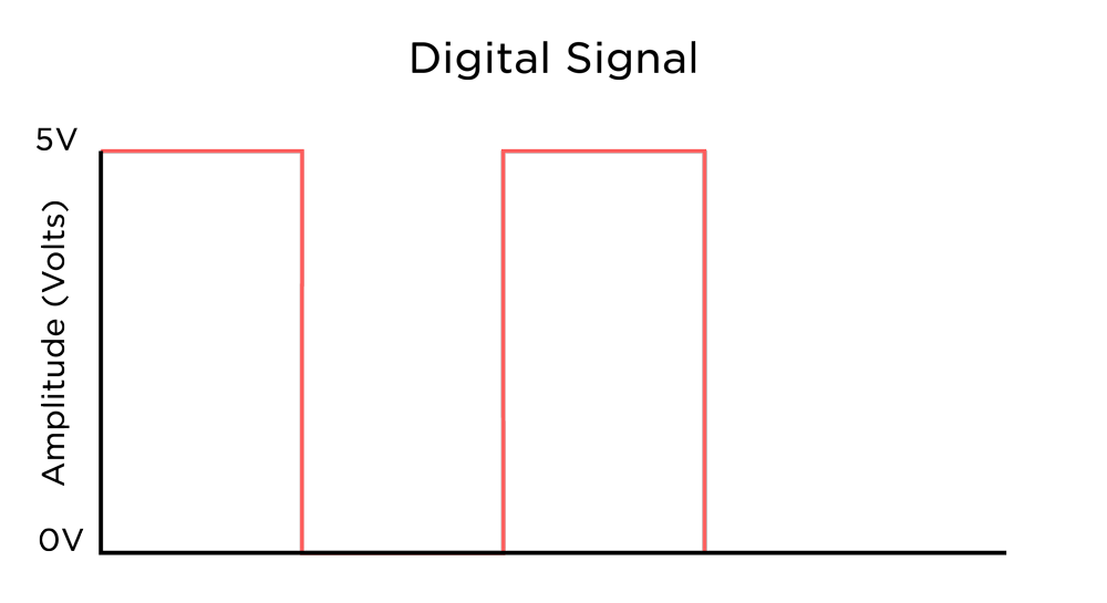
An Analogue signal however is completely different. Analogue signals can only be captured as mathematical functions, they are organic signals with an infinite resolution (down to a molecular level) which presents an issue when trying to capture them using digital logic. You might’ve heard the term 8 bit audio, or 16 bit audio etc… this is referring to the resolution that a digital system can capture an analogue signal. 8
bit resolution means that there are 256 different values that we can read, which if you zoomed in closely to an analogue waveform, consists of little steps at each of those values.
As you can see, using analogue signals in a digital system can be tricky. Whilst some special chips have the ability to output analogue voltages straight from the chip, most devices don’t have that luxury.
So how can we get an analogue output from our Raspberry Pi you ask? A bit of magic called PWM.
What is PWM?
PWM stands for Pulse Width Modulation, and it’s a clever method of using a digital output to emulate an analogue effect.
A PWM signal is essentially a pin which switches from HIGH to LOW very quickly, to a set frequency. Let’s assume we have a PWM signal at 10Khz, in other words it modulates 10000 time per second. The ‘strength’ or level of a PWM signal is determined by the duty cycle. The duty is the proportion of time spent HIGH vs LOW over one time interval.


By using PWM signals, we can easily control things like the brightness of LEDs, motor speeds etc… An LED with a PWM signal is actually flashing really quickly, however our eyes can’t interpret that flashing fast enough, so it averages the on/off time to a brightness. Likewise, due to the mechanical and electrical properties of a bushed DC motor, the motor responds to the PWM signal as an average rather than rapid switching.
The Gear
To follow along with this tutorial you will need:
- Raspberry Pi board (we recommend the Pi 3)
- Male-Male Jumper Wires
- Female-Male Jumper Wires
- LM3914 LED Bar Graph Driver
- 10 Segment LED Bar Graph
- Large Breadboard
- 2x 1uF Electrolytic Capacitors
- 1k Resistor (we recommend the Sparkfun Resistor Kit)
- 2x 4.7k Resistors
Along with this things, you will need everything required to use the Pi 3 board such as a power supply, display etc… for more info on this, check out our Hello World with Raspberry Pi tutorial. As always, we strongly recommend using the Pimoroni Pibow Coupe case. The hardware access and pin labelling will change your life
The Circuit – Part 1
To test this out, we’re going to build a really simple circuit using an LED and a current limiting resistor.

The Code
Whilst you could write out the code to create a PWM signal from scratch, it’s not a great use of time, or computer resources, but instead, the RPi.GPIO module contains easy to use functions for generating PWM outputs.
Take a look at the code below and read through the comments to understand how it works, then write the code into your Python 3 script editor. To do this go to the Menu -> Programming -> Python 3 (IDLE), then go to File -> New File.
#import modules
import RPi.GPIO as GPIO
import time

#declare variables
count = 0
delay = 0.01

#GPIO setup
ledPin = 2
GPIO.setmode(GPIO.BCM)
GPIO.setwarnings(False)

GPIO.setup(ledPin, GPIO.OUT)    #set pin 2 (ledPin) as output
pwmLed = GPIO.PWM(ledPin, 1000) #create new PWM object 'pwmLed'

pwmLed.start(0) #start PWM aat 0 duty cycle (off)

#main loop
try:
    while 1:    #infinite loop
        if count < 100: #if the variable 'count' is less than 100
            count = count   1    #add one to the variable 'count'
            pwmLed.ChangeDutyCycle(count)   #change the duty cycle to value of 'count'
            time.sleep(delay)   #wait for our delay time

        if count == 100:    #if count is equal to 100, reset count to 0
            time.sleep(delay*10)
            count = 0
            pwmLed.ChangeDutyCycle(count)
            time.sleep(delay*10)


except KeyboardInterrupt:   #if Ctrl   C is pressed, cleanly exit our program
    pwmLed.stop()
    GPIO.cleanup()
    print("Program Exited")
Your LED should ramp up to full brightness, then drop to zero, and loop.
This is all well and good, except that a PWM signal isn’t really an analogue voltage, it’s just a rapidly switching digital signal. Never fear though, there is a solution, read on to the low pass filter.
Filtering a PWM Signal
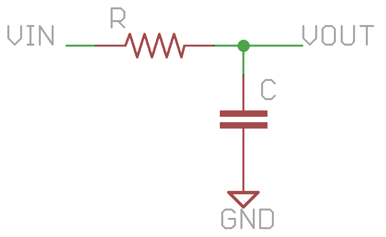 The final step in extracting a true analogue output from our Raspberry Pi is a low pass filter. A simple low pass filter can be constructed using a capacitor and resistor to form an RC network. A low pass filter (LPF) does exactly what its name implies, it allows the low frequencies to pass, whilst cutting off frequencies above a certain point. We won’t go into the theory and math behind this type of filter, that’s for another time, however the standard low pass filter looks like this:

 Using values of 4.7K and 1uF for our resistor and capacitor gives us a cut off frequency of approximately 33Hz, which well and truly blocks out the PWM modulation of 10Khz. But our filter doesn’t act like a brick wall at 33Hz, it slopes off starting at our cut-off frequency. However we can increase the steepness of that slope by adding another pole to the filter. A single RC filter is a single pole filter, if we add another RC filter in series to it, it becomes a two pole filter, with a steeper cut-off gradient.

Whilst the two curves might look similar, you can see the vertical amplitude scale is doubled for the two pole filter, giving a much steeper cut-off gradient.
Now, if we pass the PWM output through our LPF, the sudden changes in the PWM signal which occur above the cut-off frequency are filtered out, giving us a voltage proportional to the duty cycle. A 50% duty cycle will produce a voltage of roughly ½ our signal HIGH voltage.
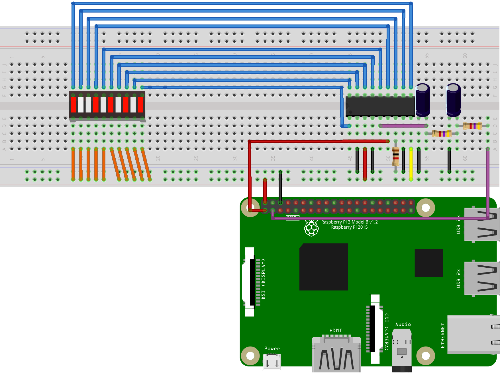
Now that we have got a nice stable analogue voltage to work with, let’s do something fun with it. Driving LED bar graphs can be fun, but uses lots of digital pins, and you need code to drive each one properly. The LM3914 is an LED bar graph driver which allows us to drive a 10 LED bar graph from an analogue voltage signal. This is useful for metering audio signals, but also allows for easy visualisation using only a signal pin.
Using the LM3914

Hooking up the LM3914 is fairly straightforward, we’ll just need a lot of jumper wires to connect everything up. Using the information from the datasheet (found here), we can work out what we need to do to get it working. The beauty of the LM3914 chip is that the current supply for the LEDs is programmable and controlled by the chip, so we only need one resistor to set the current using one of the pins, rather than one for each LED.
LED Pins: Pins 1, 10-18 are the 10 pins for our LEDs, the anode (positive side) or each LED connects to our supply voltage, and the cathode (negative side) connects the LED pins on the LM3914.
Supply Pins: Pins 2 and 3 are the supply pins for the chip, 2 (V-) will connect to ground and 3 (V ) will connect to 5V.
Divider Pins: Pins 4 and 6 set the high and low limits for our analogue input voltage. Because the output pins on the Raspberry Pi output a max of 3.3V, we’ll connect pin 6 (high) to 3.3V, and pin 4 (low) to ground.
*Note that V most be at least 1.5V greater than the high divider. 3.3V gives us 1.7V of headroom from our 5V supply voltage.*
Mode Select: This pin sets the mode that our LED bar graph will operate as. Left floating (unconnected) and our bar graph will be in dot display mode; a single LED will light up to show the input signal and all others will be off. Connected to V (5V) and our bar graph will be in bar graph mode; every LED below the signal point will light up, and only the LEDs above the signal point will be off. You can set this whichever way you would like, however we chose to use the bar graph mode, so our diagram will show it tied to V .
Reference Pins: Pins 7 (ref. out) and 8 (ref. adjust) are voltage reference pins which can be used to control the brightness and current for the LEDs. You could use a potentiometer, or even another analogue output to control the brightness, however to keep things simple, pin 7 is connected to ground via a 1k resistor to set the current draw, and pin 8 is tied straight to ground.
 The Circuit – Part 2
 The Circuit – Part 2
Awesome, now we know how the LM3914 works, let’s get it connected up to use as a bar graph.
We’re connecting everything up as per the pin descriptions above. As usual, make sure that your Raspberry Pi board is off and unplugged from power before connecting anything to the GPIO pins.
We’re connecting the positive bread board rail to the 5V output on the Raspberry Pi, and only using the 3.3V output for the reference voltage.
We're going to use the exact same code as we used to ramp the brightness of the LED previously, so run that code again, and your LED bar graph should sequence from 0-10.
What Now?
Dimming LEDs, or creating analogue signals to control the LM3914 are only a few of the many applications that you can use PWM output for. There are also many standalone DAC boards which can receive data via serial communication and convert it into audio or other analogue functions, which adds various audio functionality, however for creating simple analogue outputs, our PWM filtering method works well.

