In this guide, we will be exploring how to use PETG as a support interface layer for PLA prints (and vice versa), a multi-material technique that allows you to print perfectly clean and smooth overhangs. We are going to be looking at the basic theory of the process, how to set this up in your slicer, and the limitations across different 3D geometries. Regardless if you have a dual nozzle, or even a single nozzle printer, this method might just change the way you approach overhangs and 3d printing design.
Let's get into it!
Why This Process Works
To understand why this multi-material trick gives us better results, we first need to look at why regular supports give us a rough surface on overhangs.
If you have a shape with a massive, flat underside suspended in mid-air (like the coin-shaped object on the right) it is inherently not an ideal shape to be printed. Slicing it standing up is not an option, so you would likely slice it face down and enable supports. But the slicer has to do a bit of a balancing act here; the slicer has to make the supports stick to the part enough that it doesn't fall off, while also not sticking enough that it can be snapped off and removed.
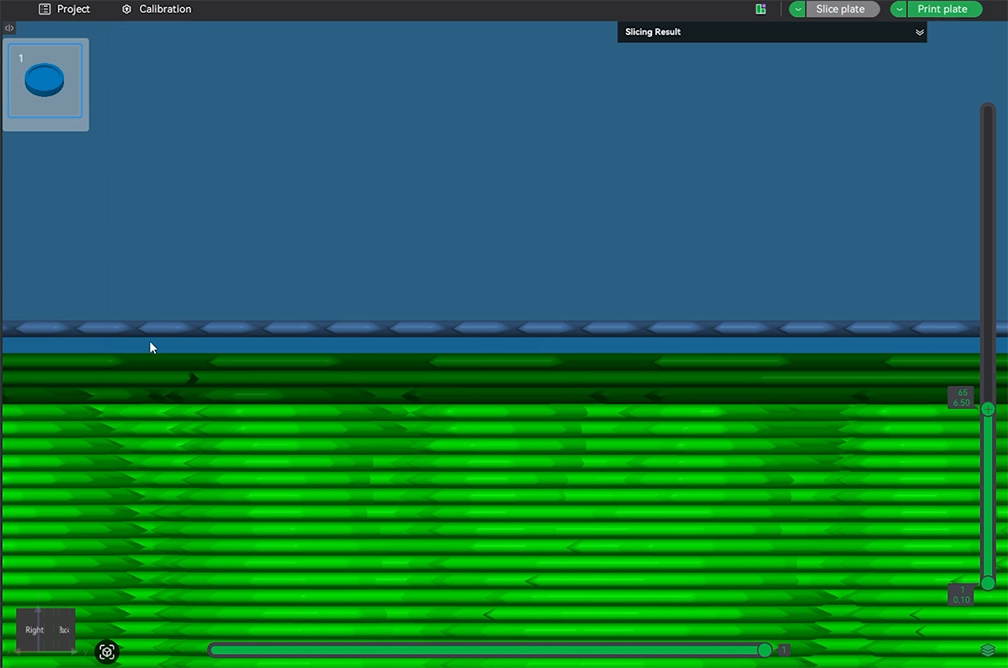
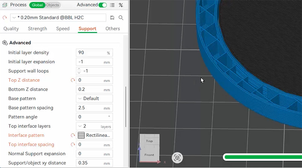
To achieve this, the slicer automatically leaves a tiny physical gap (usually about 0.2mm) between the top of the support structure and the bottom of your print. This gap creates a weak point, ensuring the support material snaps away instead of fusing into your model like a solid piece of plastic. The image on the right shows this tiny gap in slicer.
However, this gap means that you are printing over thin air (just a 0.2mm gap of it). The hot filament sags as it prints in mid-air, and this gap is largely what creates the rough surface you often see on the underside of a print. This gap is what makes support removal possible, but at the cost of a rougher surface. It's a decent middle ground that has been largely accepted, but it can be better!
This is where PETG comes in to save the day. On a molecular level, PETG (Polyethylene Terephthalate Glycol) and PLA (Polylactic Acid) are fundamentally different.
Normally, when you melt two layers of the same plastic together, the plastic molecules mix together and get tangled up. When it cools down, the molecules get locked together, and the two layers stick together! However, if you melt PLA and PETG together, their molecules naturally repel each other as they are chemically different - for similar reasons that water and oil refuse to mix. So if you print a layer of PETG DIRECTLY on top of a layer of PLA, they won't stick together!
Because they simply will not fuse together, we can cheat the system a little. We don't need that 0.2mm gap anymore! We can tell our slicer to print our PLA part directly on top of a solid layer of PETG with a 0mm gap, and they naturally won't stick. Because it's printed flush, the PLA has a perfectly flat, solid surface to rest on, eliminating a lot of the sagging and roughness on the underside of our prints. You'll also find that PETG supports are easier to remove than regular supports as well!
And of course, the same logic works in reverse. We can use PLA supports for a PETG part, and they won't stick either.
Slicer Settings
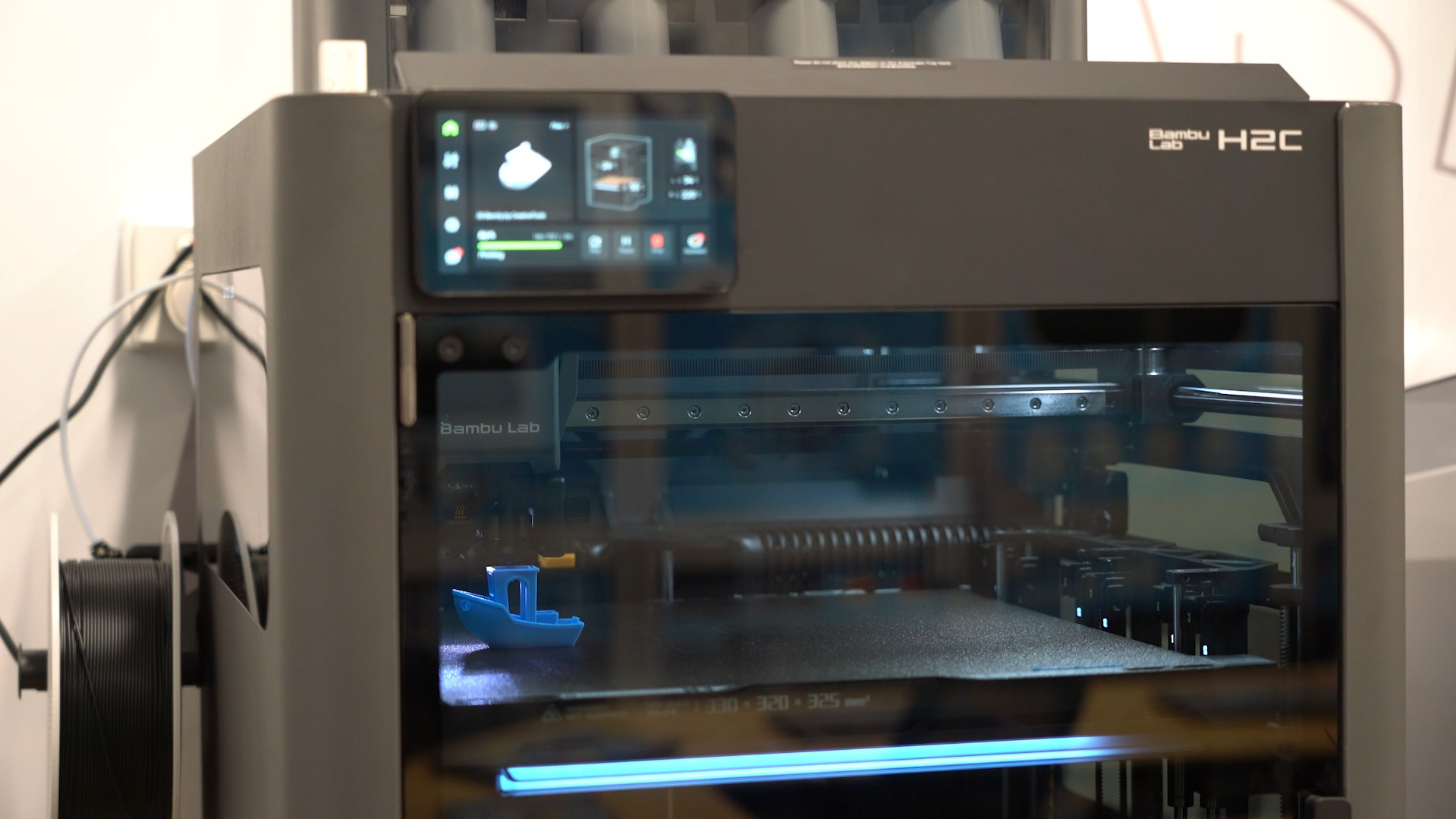
For this demonstration, we will be using Bambu Studio as we are printing on our Bambu H2C dual-extrusion printer, but I can confirm that this works in OrcaSlicer, as I have done this at home on my Bambu P1S.
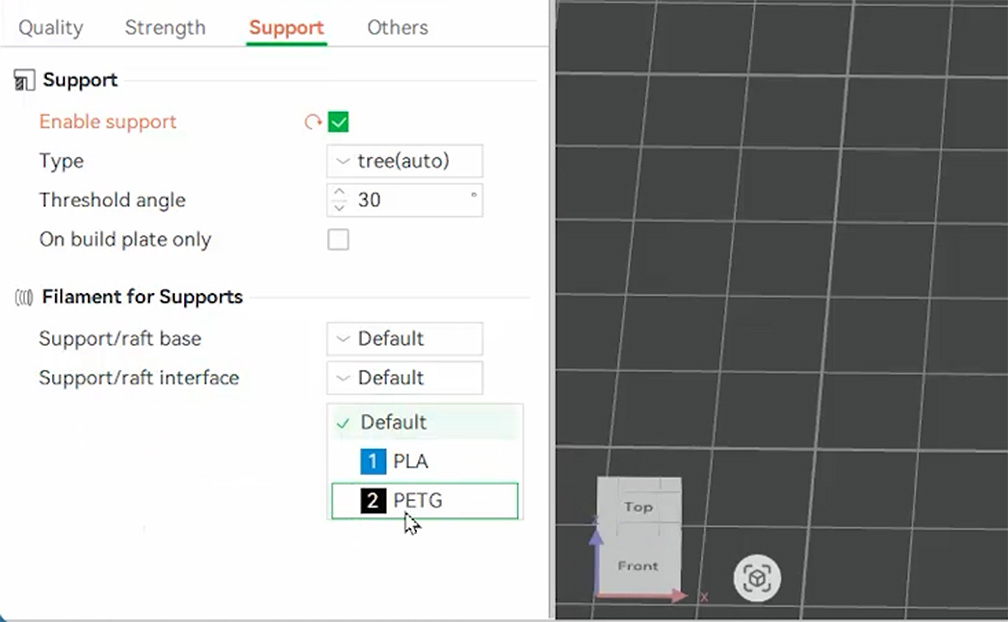
To begin, import your model (we are using our coin test piece), and ensure you have both PLA and PETG as filaments in your project. Then enable supports as usual. Next, scroll down a tad till you see a setting for Support/raft interface, and set it to PETG (or if you are printing a PETG part, select PLA). A little window will pop up asking you to change some other settings, accept the changes as they are important, and we will look at them in a bit.
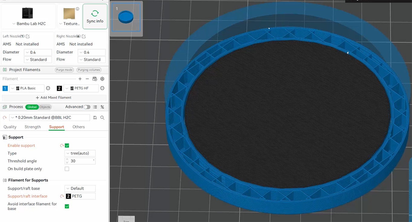
If we slice the model and take a look at the preview, you can see something interesting. The vast majority of the support structure itself is still being printed in PLA; it is only the very top contact layers that are printed in PETG. When we say "PETG supports" throughout this guide, this is what we are referring to - only the interface layer being made of PETG (though we will explore printing the entire support structure out of PETG a little later).
If we toggle on the advanced mode in our slicer, we can take a peek at those important settings that the pop-up window automatically changed for us:
- Top Z distance: First and foremost, it sets this to 0mm. As we discussed before, this is that physical gap, and because our materials don't mix, we obviously want it to be zero. (For reference, the standard default gap is usually around 0.2mm).
- Top interface pattern and spacing: When you normally slice supports, the top layer of the support structure isn't solid. It's usually printed with gaps to help prevent the PLA support from sticking too strongly to the PLA model. The image on the right shows the top layer of a regular support structure. The new settings change this pattern to be completely solid, ensuring our model has a perfectly flat foundation to build upon.
Settings-wise, that is really all there is to it!
Comparisons to Regular Supports
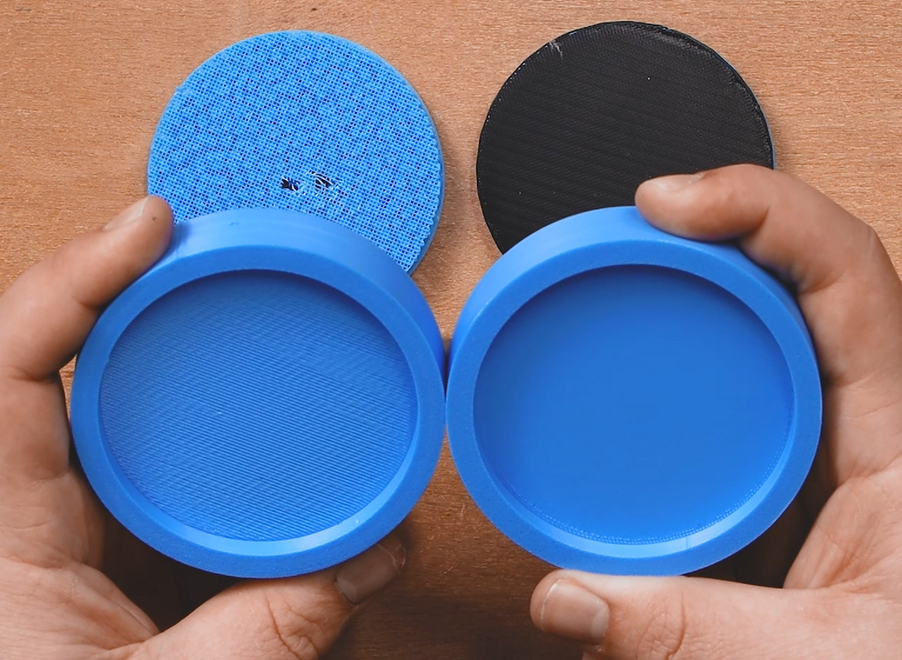
Printing our coin with this method, the support material popped off easily. And we are left with three distinct pieces: our PLA part, our PETG interface layer, and our PLA support structure, with none of them sticking to each other. It is genuinely a bit mind-bending to see three individual parts that were printed together as one solid piece come apart so cleanly.
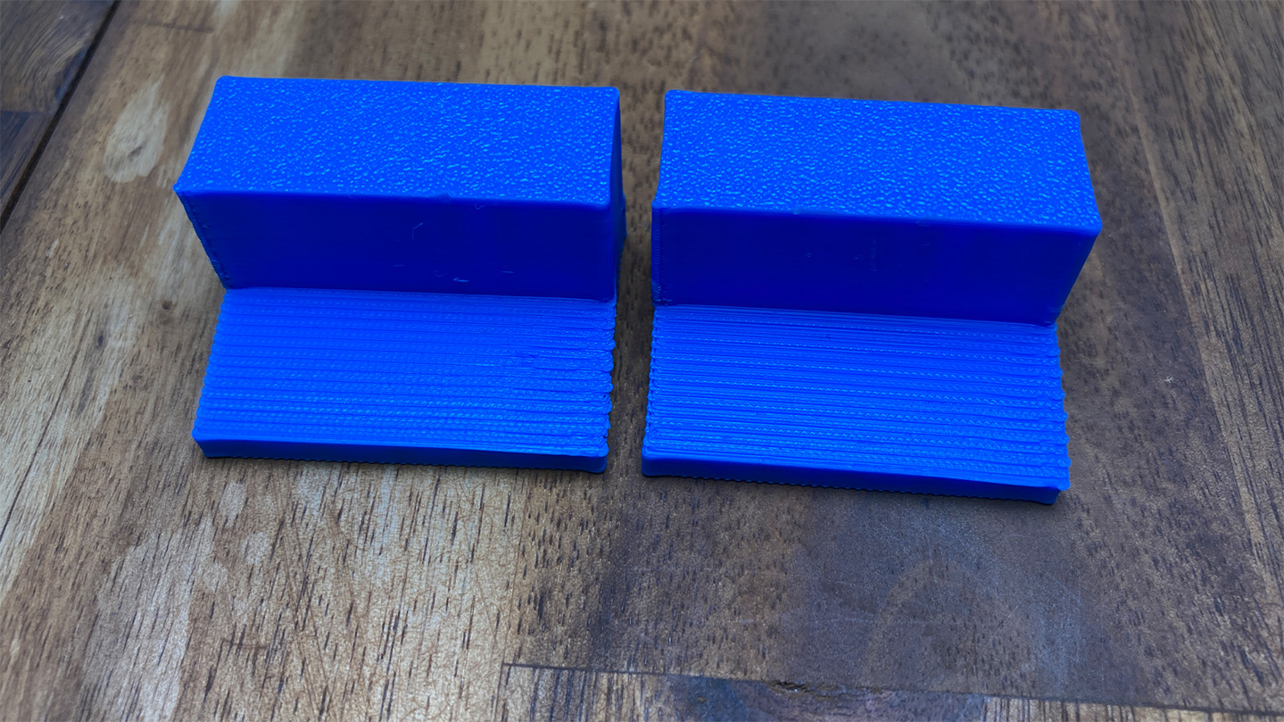
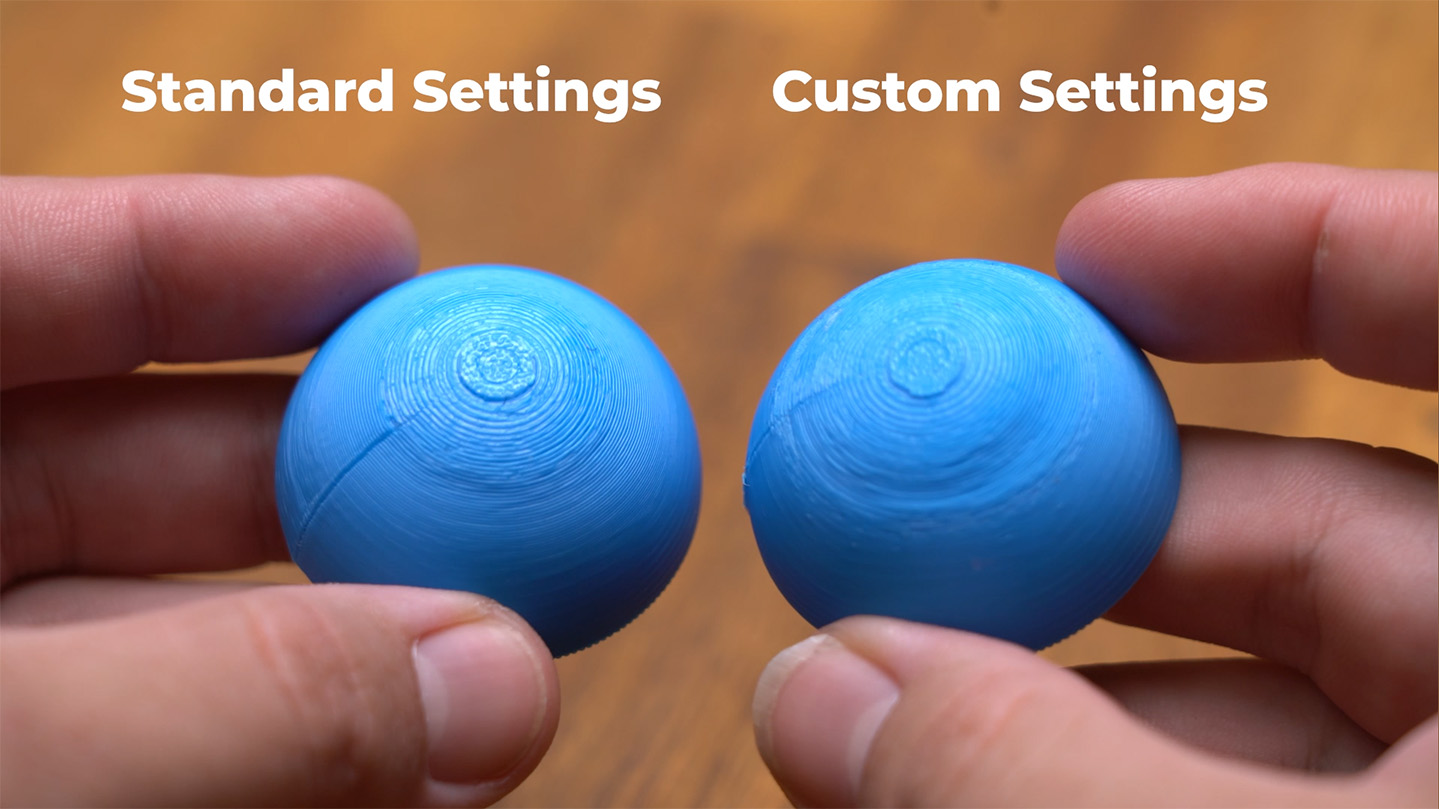
Comparing this to a coin printed with standard PLA supports, in the image on the right, the difference is quite clear. The PETG interface has made the supported surface look much better; it feels completely smooth to the touch, it's more geometrically accurate, it was easier to remove, and besides a different surface texture, it resembles the top surface of the coin.
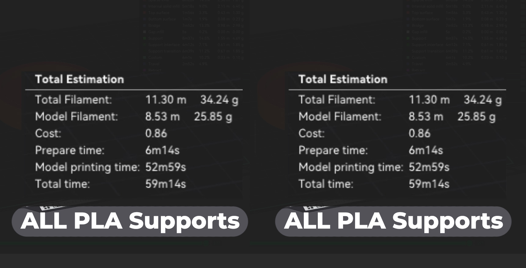
Now, to address the elephant in the room: we are using a dual-nozzle printer for this test. However, if you are using a single-nozzle printer with an automatic material system (like an AMS), this specific Coin example doesn't actually use much more filament, nor did it drastically increase the print time. We will break down this later in more detail, but for flat, parallel overhangs like this coin, this method is an absolute no-brainer even on single-nozzle machines.
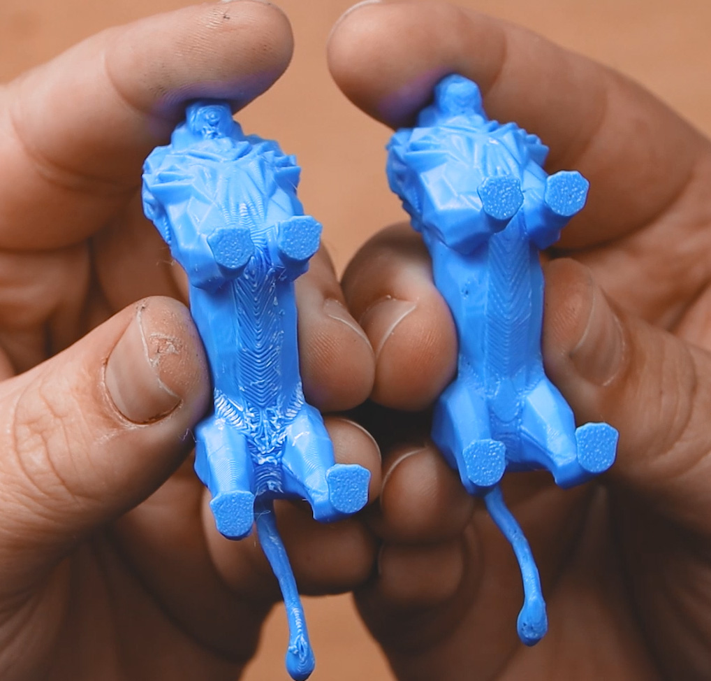
But how does this technique hold up on more complex geometries? To find out, we tested a statue-like model we'll call "Lion", a very common scenario for needing support. Again, the results were fantastic, as shown in the image on the right. Compared to regular PLA supports, there was significantly less sagging and a much smoother surface.
However, if you look closely at the results, you may see a bit of a distinct flaw: tiny black spots of PETG were permanently stuck inside our final PLA part. In the image on the right, you can see one on the side of the belly of the lion on the right.
Why did this happen? Well, for these initial tests, we grabbed a spool of wet PETG straight off the shelf. When your PETG isn't fully dialled in (or is full of moisture), it tends to string and create tiny blobs while printing that crucial interface layer. When the printer then lays the first layer of PLA over the top, those stray PETG blobs get swallowed up and embedded into the PLA part.
Once we properly dried our filament for later tests, the large majority of these black blobs disappeared. The important takeaway here is that your PETG profile must be dialled in for this to work flawlessly. If you are printing a functional part, a few discoloured specks are no worries. But for a display piece where colour matters, it might be a good idea to use the exact same colour for both your PLA and PETG, just to hide any potential imperfections!
An Interesting Observation: When doing the reverse (printing a PETG part with a PLA support interface), this blobbing issue is almost non-existent. PLA just prints so cleanly by default that it rarely blobs up the way PETG can.
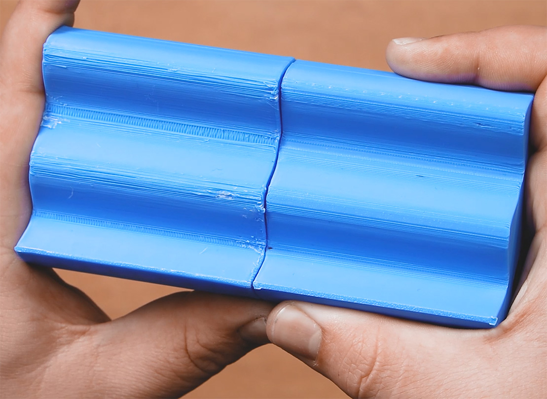
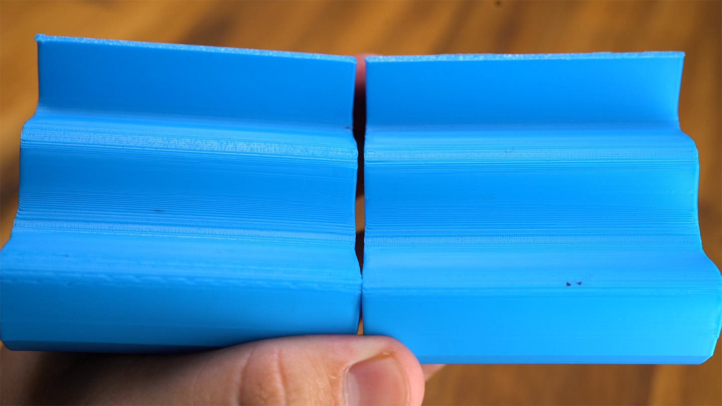
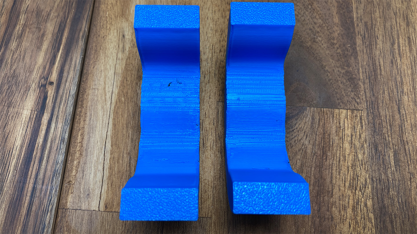
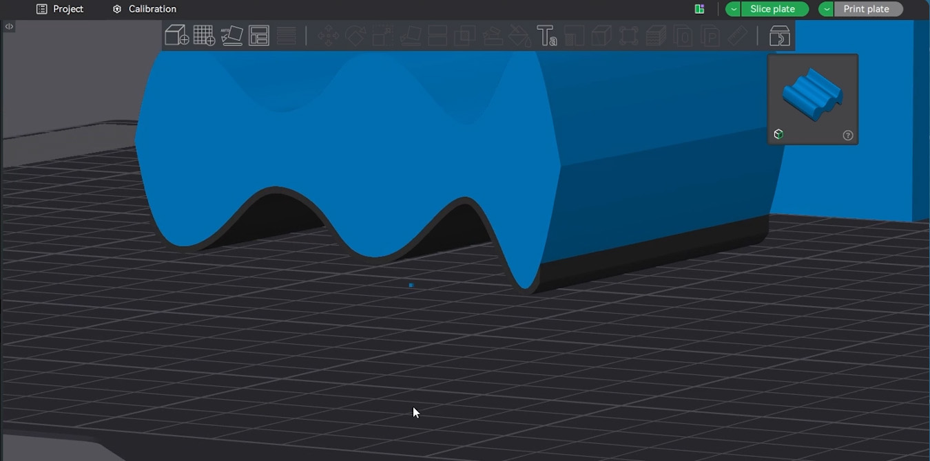
We then threw a printer's nightmare at it: a curvy piece printed almost entirely in mid-air that we call "Wiggly". Yet again, it was a night-and-day difference between PETG interfaces and regular supports. They were smoother, had less sagging, and were easier to remove most of the time.
We also ran some generic overhang angle tests. On extreme 70 or 80-degree overhangs, the multi-material supports offered a noticeable improvement, though the difference was less pronounced on shallower angles. One minor quirk we noticed on these steep overhangs was a slight "elephant footing" effect right where the first layer of PLA touched the PETG. It wasn't anything crazy and could easily be cleaned up with a hobby knife, but it is an artifact that pops up on certain angles.
We have been printing a heap of other parts around the office for other non-guide purposes with this method, and every single thing requiring supports came out better with this interface layer method.
However, as you may have gathered, this method works better on some shapes than others. The flat, parallel overhang of the Coin is the undisputed poster child of this technique. With regular PLA supports, it would probably score a 7.5/10, but with PETG supports, we would give that underside a 9.5/10. It is incredibly close in quality to the top side. The curved, organic undersides of shapes like Wiggly or the lion? We would probably say it improved from a 4/10 to a 6/10 or 7/10. There is a large improvement, but it's not as perfect as the coin.
Testing Improved PETG Supports
So, that got us thinking: if flat surfaces like the Coin get a perfect 9.5 out of 10, could we tweak a few slicer settings to get those tricky curved and organic geometries looking just as good?
The answer is... eh, sorta?
We started playing around with our support settings, and after a bunch of test prints, we found a combination that yielded slightly better results on curvy, organic surfaces:
- Threshold Angle: Bumping this up from the default 30 degrees to 40 or even 50 degrees.
- Support/raft interface layers: Increasing the PETG interface layers from the default of 2 up to 4 or sometimes 5 layers.
However, we need to put a massive emphasis on the word "marginal" here. By tweaking these settings, our Wiggly test piece went from a 7 out of 10 to maybe an 8 out of 10. The Lion statue was also a tiny bit better, but you would need to look closely; there was probably a 0.5 point increase in quality. But our simple overhang tests saw absolutely no gains, another test piece called Archy saw no improvement whatsoever either, and interestingly, an upside-down sphere test actually came out worse every single time.
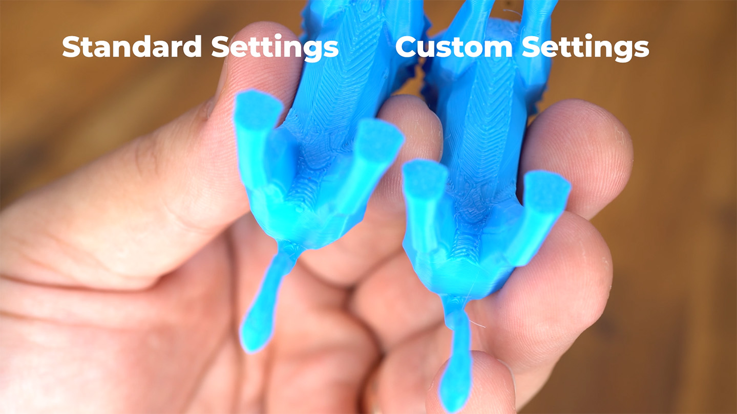
In all the following images, the default PETG interface settings are on the left, and the "enhanced" settings are on the right. A lot of these minor differences didn't come through on camera as you often need to rotate them around in the light to see the improvement.
Some reasoning on these more aggressive supports. There could be a wealth of reasons why this sometimes works / sometimes doesn't, but here is a guess from our many years of 3D printing.
When Bambu Studio tries to generate the interface layer, it seems to be quite reserved with it, and in shapes with steeper curves, it seems like it REALLY tries not to use it. In fact, even with PETG support layers enabled, in places it would ignore it and place a PLA support surface instead and refuse to generate a PETG one. OrcaSlicer seemed to do this even more so as well.
This is why we bumped up the overhang threshold and the thickness of the interface layer. It seemed to trick the slicer into generating the interface layer better, and in shapes like the lion and wiggly, where the slicer wasn't generating enough interface on its sharper curves, we got a bit better results. These better results came from the fact that more surfaces that needed supporting, were being supported by the interface layer.
However, and this is our guess, with shapes like the simple overhang tests, and the archy shape, the slicer was already generating the supports as needed, so the benefits were not seen. But why did it come out worse on the sphere? We thought this was a misprint and did it again and found the exact same results.
We are unsure exactly why, but from noticing it in other tests, a curved surface that contacted the PETG support layer ALWAYS came out slightly rough. Better than standard supports, but always a bit rough. On the sphere when we bumped up the overhang threshold, parts of the sphere that could happily print without supports were suddenly being supported. So parts that could print cleanly without them were suddenly over-supported, leading to a rougher result. This is probably happening to some extent on other curved pieces, but on the simple geometry of a sphere it is probably most aparent.
Long story short: tweaking these settings can lead to a slightly better underside on specific organic shapes, playing around with these settings is well into the territory of diminishing returns. If you end up experimenting with these interface settings and find a magical combination that works flawlessly for curves, please do let us know!
This was not the end of our "enhanced" supports quest; we had a few more things to try.
In experimenting, trying to fix the slicer not generating enough PETG supports, we ran a few tests on different shapes where we manually modelled in a custom solid shape beneath the part that would be printed out of PETG. There were some instances where this gave again VERY marginal improvements, but the effort was deemed not to be worth it.
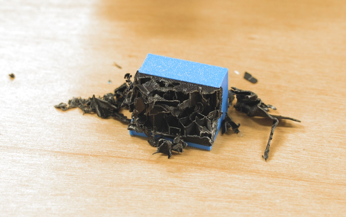
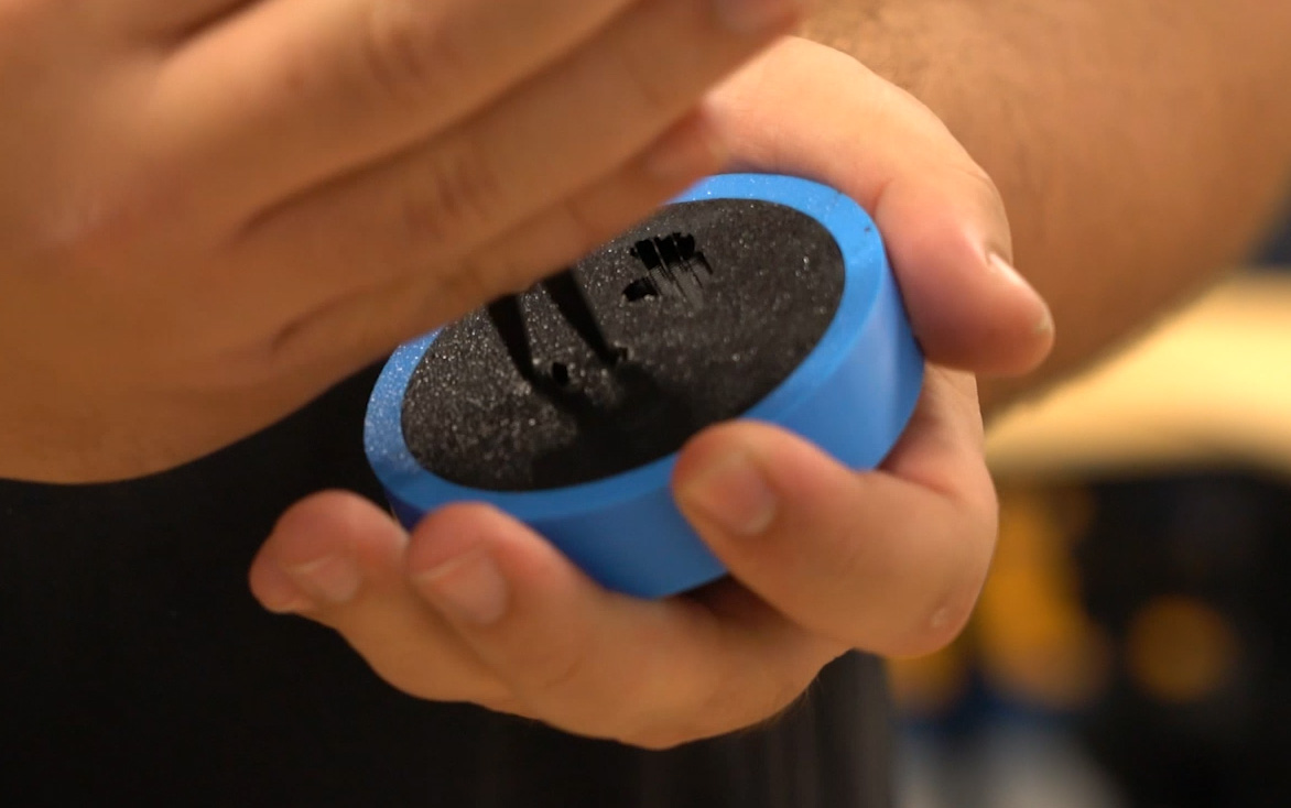
At best, it gave basically the same result as increasing the overhange threshold and interface thickness in the slicer, and at worst, it created a support structure that could not be removed, as shown on the right.
In fact, that image above highlights an issue you may encounter if you play around with more aggressive support structures - they stick too well.
We think there are two reasons for this. First, standard slicer-generated support material is designed with thin walls and sparse patterns so it can bend, crumple, and break away easily. A solid, manually modelled block of plastic cannot do that.
Second, when a vertical wall of PETG is printed flush against a vertical wall of PLA (like two books touching each other while standing up on a shelf), the physical layer lines create a mechanical lock. Even though they aren't chemically sticking, the horizontal ridges of the PLA layer lines sink into the horizontal grooves of the PETG layer lines. It creates a zipper or "Velcro" effect. It is exactly like taking two phone books and interleaving their pages one by one; the friction makes it physically impossible to pull them apart. The image on the right is an extreme case of this where the PETG and PLA were stuck so tightly together they could not be removed.
We actually encountered this Velcro effect from time to time as well. If we set the overhang threshold too high, or if we had bad PETG bubbling from wet filament, this mechanical locking would make it quite difficult to remove supports. It is definitely something to keep in mind if you start experimenting with your settings!
For our final round of testing, we went back to the slicer and changed not only the interface layer, but the entire support structure to be made of PETG.
The results? We didn't really get a better underside surface, and logically, there is no reason why we would have, since the actual contact layer remains exactly the same.
If anything, this approach was a bit more of a hassle because you are now trying to print large amounts of both PETG and PLA directly onto the same print bed. This creates a temperature clash. Generally, PLA likes a cooler bed, while PETG needs a hotter bed to prevent warping. Luckily, if you are using a textured PEI sheet, the maximum recommended bed temperature for PLA is about 60°C, and the absolute minimum for PETG is about 60°C. If you manually adjust your filament profiles, you can force them to meet in the middle and make it work.
But honestly, this is just extra effort to get the exact same results. While printing the entire structure in PETG did make removing the supports on the flat Coin and the lion models a tiny bit easier, it is such a niche case that we would probably just stick to using PETG for the interface layers only.
The Verdict and When You Should Use This
Alright, let's round this up and interpret what these results actually mean for your daily 3D printing workflow. Ultimately, whether you should use this technique comes down to the shape of your model and the printer you have.
If your part has a flat overhang surface that is parallel to the print bed (like our Coin, or the underside of the letter H or T), PETG support interfaces are an absolute no-brainer, even on a single-nozzle printer!
Because the interface is so thin, there are only a couple of layers of PETG being printed, meaning the nozzle only has to swap filaments twice. On a single-nozzle machine with an AMS (like a P2S, or an A1), the prime tower and the purged filament "poops" ejected out the back only waste an extra 2 to 3 grams of material, which is practically nothing. In terms of print time, this PETG interface only added about 8 minutes to the Coin compared to printing with regular PLA supports.
Because the time and material costs are so low, we simply don't stress about flat, parallel overhangs anymore. Yes, we will still avoid them if it's an easy design fix, or if we are mass-producing 200 of a specific part. But for regular, everyday prints? We are confident the supports will give us a surface quality nearly identical to the topside.
Curved and organic surfaces are where you really have to decide if the juice is worth the squeeze.
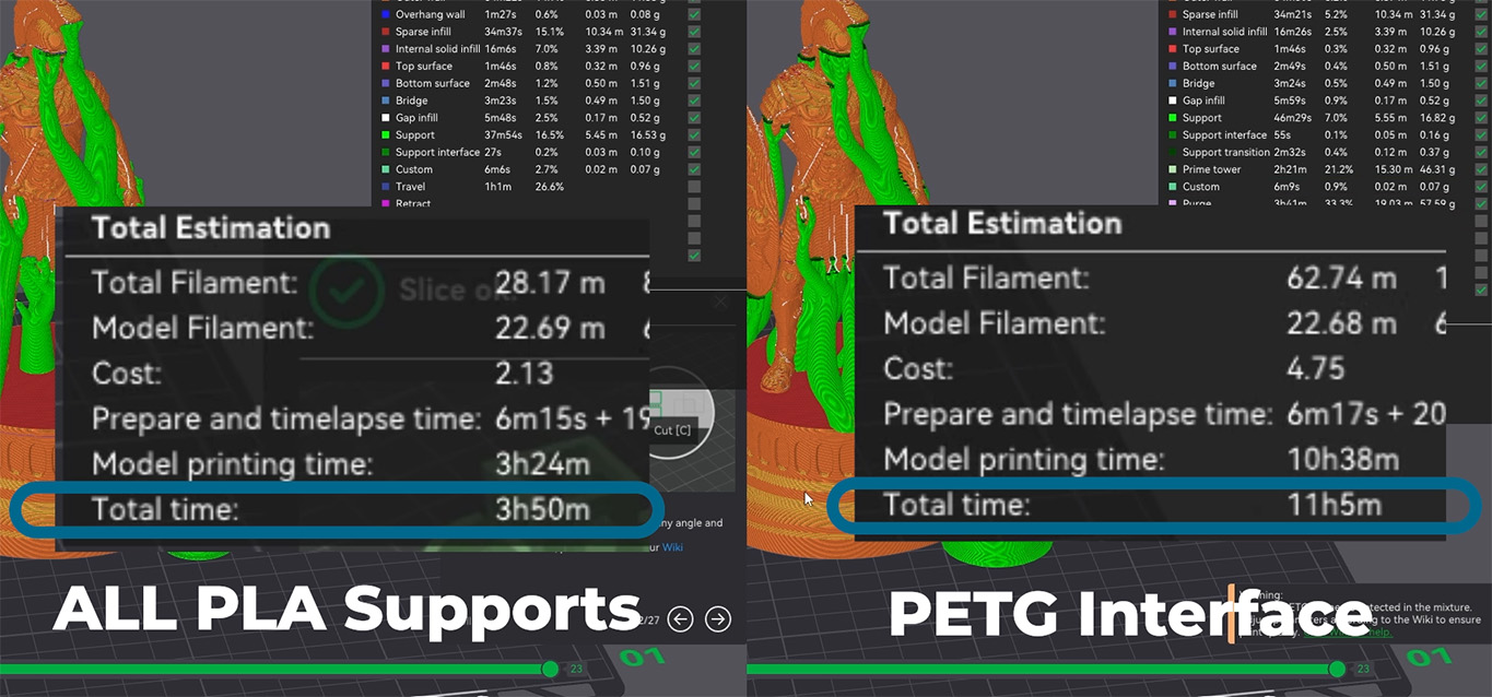
First of all, as we saw with the Wiggly and Lion tests, the quality is greatly improved, but it's not flawless like the flat Coin. More importantly, trying to use PETG support interfaces on a single-nozzle printer for a complex curve is a massive time sink. Because the printer has to constantly swap filaments on every single layer of that curved interface, you can expect anywhere from a 30% increase to double or even triple the total print time compared to regular PLA supports. On top of that, you are wasting a significant amount of material with the nozzle needing to be purged repeatedly.
So, on a single-nozzle printer, you will really need to weigh up whether you just use ye olde PLA supports or a PETG interface, depending entirely on how badly you want that nicer underside.
If you have a dual-nozzle printer like the H2C or the H2D? Well, none of that matters!
Because you have two dedicated nozzles, your printer is handling two materials simultaneously without needing to constantly cut, swap, and purge filament. It is going to take roughly the exact same amount of time and material as standard supports, so you might as well do it! On a dual-nozzle machine, PETG interface layers are an almost free upgrade in underside surface quality, costing little more than having both filaments loaded and a prime tower that weighs a few grams.
Mid-range 3D printers with dual nozzles are becoming more common with releases such as the Bambu X2D, and this specific technique is honestly one of the biggest arguments for upgrading to one of these machines. For not much more in price, the ability to have a dedicated support interface nozzle is quite worth.
We hope we have convinced you to give this a try! If you have a dual-nozzle printer, this is basically a single button press in your slicer to get vastly improved overhangs. And if you are rocking a single-nozzle machine at home, it is still an incredibly worthwhile trick to keep up your sleeve for flat overhangs.
If you experiment with your slicer and find a way to get even better results with multi-material supports on curved surfaces, or if you just have a question about something we covered in this guide, feel free to head on over to our community forum at the bottom of this page. We are all makers and happy to help!
Until next time though, happy making!