
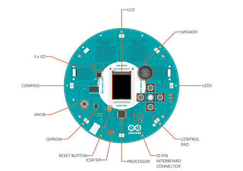
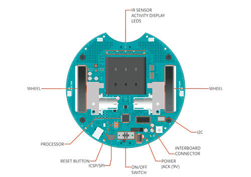
The Arduino Robot is the first official Arduino on wheels. The robot has two processors, one on each of its two boards. The Motor Board controls the motors, and the Control Board reads sensors and decides how to operate. Each of the boards is a full Arduino board programmable using the Arduino IDE.
Both Motor and Control boards are microcontroller boards based on the ATmega32u4 (datasheet). The Robot has many of its pins mapped to on-board sensors and actuators.
Programming the robot is similar to the process with the Arduino Leonardo. Both processors have built-in USB communication, eliminating the need for a secondary processor. This allows the Robot to appear to a connected computer as a virtual (CDC) serial / COM port.
As always with Arduino, every element of the platform – hardware, software and documentation – is freely available and open-source. This means you can learn exactly how it's made and use its design as the starting point for your own robots. The Arduino Robot is the result of the collective effort from an international team looking at how science can be made fun to learn. Arduino is now on wheels, come ride with us!
Control Board Summary

Motor Board Summary

Schematic & Reference Design
EAGLE files for control and motor boards: arduino-robot-reference-design.zip
Power
The Arduino Robot can be powered via the USB connection or with 4 AA batteries. The power source is selected automatically.
The battery holder holds 4 rechargeable NiMh AA batteries. NB : Do not use non-rechargeable batteries with the robot
For safety purposes, the motors are disabled when the robot is powered from the USB connection.
The robot has an on-board battery charger that requires 9V external power coming from an AC-to-DC adapter (wall-wart). The adapter can be connected by plugging a 2.1mm center-positive plug into the Motor Board's power jack. The charger will not operate if powered by USB.
The Control Board is powered by the power supply on the Motor Board.
Memory
The ATmega32u4 has 32 KB (with 4 KB used for the bootloader). It also has 2.5 KB of SRAM and 1 KB of EEPROM (which can be read and written with the EEPROM library).
The Control Board has an extra 512 Kbit EEPROM that can be accessed via I2C.
There is an external SD card reader attached to the GTFT screen that can be accessed by the Control Board's processor for additional storage.
Input and Output
The Robot comes with a series of pre-soldered connectors. There are a number of additional spots for you to install additional parts if needed.
All the connectors are labelled on the boards and mapped to named ports through the Robot library allowing access to standard Arduino functions. Each pin can provide or receive a maximum of 40mA at 5V.
Some pins have specialized functions:
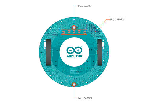
Control Board TK0 to TK7: these pins are multiplexed to a single analog pin on theControl Board's microprocessor. They can be used as analog inputs for sensors like distance sensors, analog ultrasound sensors, or mechanical switches to detect collisions.
Control Board TKD0 to TKD5: these are digital I/O pins directly connected to the processor, addressed using Robot.digitalRead() and Robot.digitalWrite) functions. Pins TKD0 to TKD3 can also be used as analog inputs with Robot.analogRead() Note: if you have one of the first generation robots, you will see that the TKD* pins are named TDK* on the Robot's silkscreen. TKD* is the proper name for them and is how we address them on the software.

Motor Board TK1 to TK4: these pins are named in software as B_TK1 to B_TK4, they can be digital or analog input pins, and support Robot.digitalRead(), Robot.digitalWrite) and Robot.analogRead().

Serial Communication: The boards communicate with each other using the processors' serial port. A 10-pin connector connects both boards carries the serial communication, as well as power and additional information like the battery's current charge.
Control Board SPI: SPI is used to control the GTFT and SD card. If you want to flash the processor using an external programmer, you need to disconnect the screen first.
Control Board LEDs: the Control Board has three on-board LEDs. One indicates the board is powered (PWR). The other two indicate communication over the USB port (LED1/RX and TX). LED1 is also accessible via software.
Both boards have I2C connectors available: 3 on the Control Board and 1 on the Motor Board.
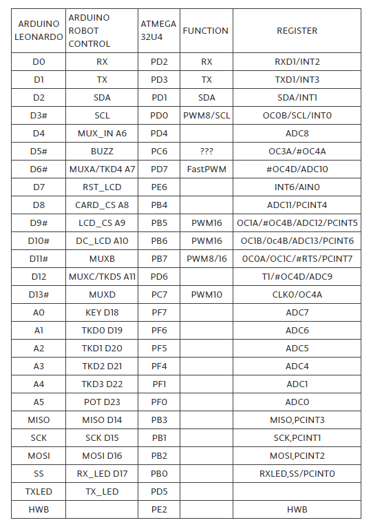
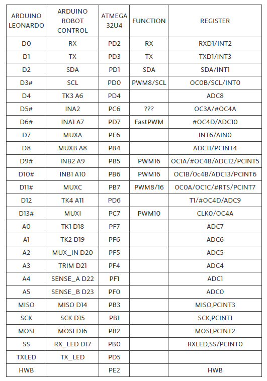
Control Board Pin Mapping
Motor Board Pin Mapping
Communication
The Robot has a number of facilities for communicating with a computer, another Arduino, or other microcontrollers. The ATmega32U4 provides UART TTL (5V) serial communication, which is available on digital the 10-pin board-to-board connector. The 32U4 also allows for serial (CDC) communication over USB and appears as a virtual com port to software on the computer. The chip also acts as a full speed USB 2.0 device, using standard USB COM drivers.On Windows, a .inf file is required. The Arduino software includes a serial monitor which allows simple textual data to be sent to and from the Robot board. The RX (LED1) and TX LEDs on the board will flash when data is being transmitted via the USB connection to the computer (but not for serial communication between boards).
Each one of the boards has a separate USB product identifier and will show up as different ports on you IDE. Make sure you choose the right one when programming.
The ATmega32U4 also supports I2C (TWI) and SPI communication. The Arduino software includes a Wire library to simplify use of the I2C bus; see the documentation for details. For SPI communication, use the SPI library.
Programming
The Robot can be programmed with the Arduino software (download). Select "Arduino Robot Control Board" or "Arduino Robot Motor Board" from the Tools > Board menu.
The ATmega32U4 processors on the Arduino Robot come preburned with a bootloaderthat allows you to upload new code to it without the use of an external hardware programmer. It communicates using the AVR109 protocol.
You can bypass the bootloader and program the microcontroller through the ICSP (In-Circuit Serial Programming) header.
Automatic (Software) Reset and Bootloader Initiation
Rather than requiring a physical press of the reset button before an upload, the Robot is designed in a way that allows it to be reset by software running on a connected computer. The reset is triggered when the Robot's virtual (CDC) serial / COM port is opened at 1200 baud and then closed. When this happens, the processor will reset, breaking the USB connection to the computer (meaning that the virtual serial / COM port will disappear). After the processor resets, the bootloader starts, remaining active for about 8 seconds. The bootloader can also be initiated by double-pressing the reset button on the Robot. Note that when the board first powers up, it will jump straight to the user sketch, if present, rather than initiating the bootloader.
Because of the way the Robot handles reset it's best to let the Arduino software try to initiate the reset before uploading, especially if you are in the habit of pressing the reset button before uploading on other boards. If the software can't reset the board you can always start the bootloader by double-pressing the reset button on the board. A single press on the reset will restart the user sketch, a double press will initiate the bootloader.
USB Overcurrent Protection
Both of the Robot boards have a resettable polyfuse that protects your computer's USB ports from shorts and overcurrent. Although most computers provide their own internal protection, the fuse provides an extra layer of protection. If more than 500 mA is applied to the USB port, the fuse will automatically break the connection until the short or overload is removed.
Physical Characteristics
The Robot is 19cm in diameter. Including wheels, GTFT screen and other connectors it can be up to 10cm tall.
Conformity Declaration
Exact shipping can be calculated on the view cart page (no login required).
Products that weigh more than 0.5 KG may cost more than what's shown (for example, test equipment, machines, >500mL liquids, etc).
We deliver Australia-wide with these options (depends on the final destination - you can get a quote on the view cart page):
- $3+ for Stamped Mail (typically 10+ business days, not tracked, only available on selected small items)
- $7+ for Standard Post (typically 6+ business days, tracked)
- $11+ for Express Post (typically 2+ business days, tracked)
- Pickup - Free! Only available to customers who live in the Newcastle region (must order online and only pickup after we email to notify you the order is ready). Orders placed after 2PM may not be ready until the following business day.
Non-metro addresses in WA, NT, SA & TAS can take 2+ days in addition to the above information.
Some batteries (such as LiPo) can't be shipped by Air. During checkout, Express Post and International Methods will not be an option if you have that type of battery in your shopping cart.
International Orders - the following rates are for New Zealand and will vary for other countries:
- $12+ for Pack and Track (3+ days, tracked)
- $16+ for Express International (2-5 days, tracked)
If you order lots of gear, the postage amount will increase based on the weight of your order.
Our physical address (here's a PDF which includes other key business details):
40 Aruma Place
Cardiff
NSW, 2285
Australia
Take a look at our customer service page if you have other questions such as "do we do purchase orders" (yes!) or "are prices GST inclusive" (yes they are!). We're here to help - get in touch with us to talk shop.
Have a product question? We're here to help!
Guides

The Maker Revolution
Projects

The Rats Nest VCC Desktop Power Supply

Remote-Controlled Mars Rover

FlipperMate: Hands-Free Pinball

Makers love reviews as much as you do, please follow this link to review the products you have purchased.
Product Comments