So you’ve got your Particle Photon or Electron, you’ve got your sensors and external components and you’re ready to build an IoT device to make the world your slave. But hang on a minute, the sensor you have only operates on 5V and you vaguely recall that using 5V with the Particle I/O pins could be bad. Well you’re not wrong, that would be very bad. You see, the Particle Photon/Electron, like many other DIY platforms operates on 3.3V rather than 5V. If you’re not sure what we mean talking about voltage levels and other such terms, check out our Analogue Electronics Crash Course to get a handle on how electricity and electronics components all work. Particle does say that the some of the pins are 5V tolerant, meaning they won't be damaged by 5V, but certainetly won't outpt 5V, however it's better practice to protect them all.
Logic Levels
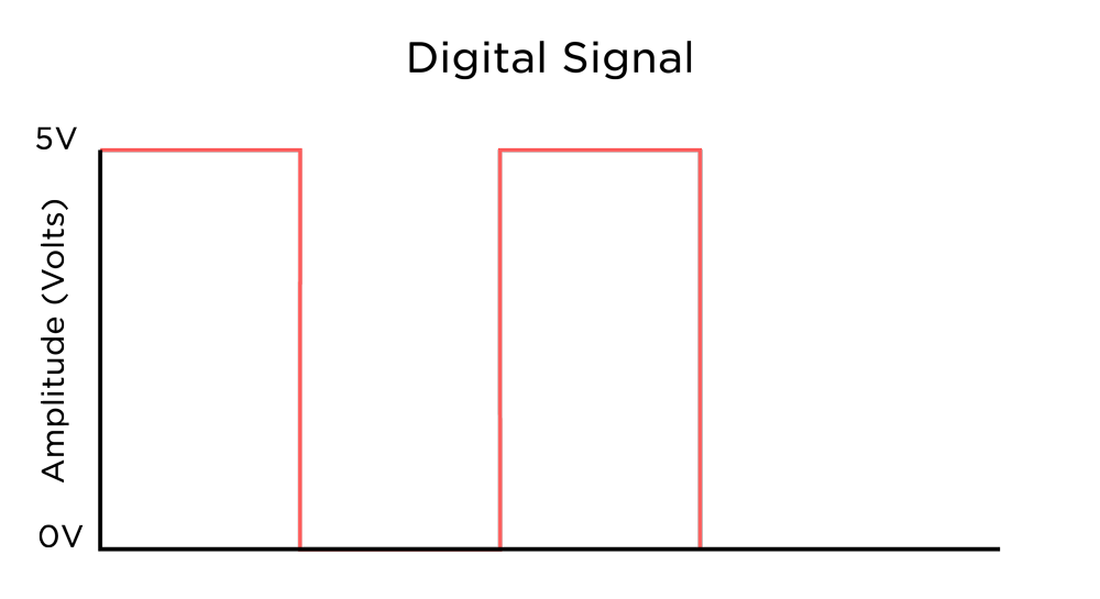
So what do we mean when we’re talking about logic levels? Simply put, a logic level is the voltage recognised by a system as the typical voltage of a high signal. This voltage level issued used by chips to determine whether the signal is high or low (binary logic) and then can make computations based off that. Traditionally, 5V was the default logic level for most systems, however as silicon chips have gotten smaller and more efficient, 3.3V is now the standard for most microprocessors (higher level processors like those found in modern desktops/laptops can be as low 1.2V).
The issue with this is that for a chip running at 3.3V, if you connect 5V up to its pins, unless it’s specifically tolerant to the higher voltage, you can risk damaging the pin, or the entire chip. Now that damage only goes one-way. If you connect 3.3V up to a 5V pin, you won’t damage it, however 3.3V may not be high enough for it to register a high signal, so it may not work properly. So the general rule of thumb is to match the logic level voltage of external components, shields, modules, or other boards to the board/chip you’re connecting to. Now how can we interface two things that operate on different voltages? A magic piece of hardware called a ‘Logic Level Converter (or shifter)’.
Logic Level Converters
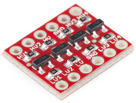 One of our most popular logic level converters is this one from Sparkfun. It’s a four channel, bi-directional converter which is awesome because it means that it will convert from a high to a low voltage, and from a low to a high voltage which makes it so handy to have going between 3.3V and 5V devices. Now don’t think that this board will step-up your 3.3V to 5V by itself. You can see on the board the HV and LV pads which means you need to have 3.3V and 5V lines to connect to it, and then the on board BSS138 FET shifts the signal up or down. You can use this board with voltages other than 5V and 3.3V (the BSS138 is rated for up to 50V) however it’s mostly used for shifting these logic level voltages. Now we know a bit about what logic level converters are, let’s take a look at how to use them to interface 5V devices with our Raspberry Pi.
Using Converter with Particle
Let’s say that we’re using an I2C bus to communicate with various devices in a project and we want our Photon/Electron to be on this bus too, but the logic level of the I2C bus is 5V, well we can use the Sparkfun logic level converter to connect our Particle board up to it. Bear in mind you can use this to interface with a sensor or output device as well, but because the I2C bus is capable of bi-directional communication, it highlights the bi-directional capabilities of the converter. So let's use the converter to connect an Arduino Uno (5V) via I2C to our Photon (3.3V). Note that whilst we're using a Photon in this example, this is compatible with the Electron too.

As you can see, it’s incredibly simple, and we’ve attached ground wires along with voltage taps from each board, then connected the SDA and SCL wires from each board to the converter which will take care of the voltages, and we can use the I2C bus to communicate bi-directionally without any danger of damaging the Photon from the 5V.
The Sparkfun converter used in this tutorial is our favourite converter by far and because they’re so cheap, it’s well worth keeping a few on hand for projects of any kind.

