Electronics is fun, so far we have covered off on communicating between devices, making LEDs flash and LCD screen operation. However using electricity to control some form of movement in your project is a fun and interesting aspect to investigate. There is no better place to start than electric motors! We are going to learn the basic principles of an electric motor, common specifications to be aware of when working with electric motors and some key differences between the types of motors available to us.
Electric motors take electrical energy and convert it to mechanical energy. We see motors every day, in fans, blowers, pumps, tools, appliances and the list goes on! We will narrow our focus to DC motors for this tutorial. The two types of motors at the focus of today’s tutorial are brushed and brushless DC motors; both of which turn electromagnetic energy into a rotational force.
Magnets, how do they work?!

The basic principle of magnets is that opposite charges attract each other, I’m sure at least once in your life you have tried to force the same end of two magnets together and found they really do not want to go. Electromagnets allow us to decide the charge of a piece of metal at a certain time. By controlling the charge of a magnet, we can choose when to attract and when to repel charges.
Inside a brushed DC motor, we have any number of field magnets that generate a constant charge. This field surrounds electromagnets that are attached to a spinning armature. When the brushes come into contact with the commutator (which is attached to the armature) the charge of the electromagnets is changed. This continual process creates rotational motion. Unfortunately, as the brushes physically contact the commutator, they can wear down giving these motors a limited lifespan.
The answer? Brushless Motors.
Brushless motors remove this susceptibility to mechanical wear by changing the charge of the magnets around the armature. The field magnets are now attached to the armature. The brush/commutator system of control is replaced by a simple electrical controller that switches the charge of the now surrounding electromagnets to keep the armature turning. This design change has a bunch of benefits namely higher efficiency (more mechanical energy for power provided), less noise and a longer lifespan!
Common Specifications
Operating voltage: This is a voltage that the motor is designed to operate at. By design, it's the voltage at which your motor will have the most optimal performance. Refer to this voltage when finding a power source for your motor driver circuit.
Rated Speed: This is the speed the motor will run at when operating at the specified voltage. Usually measured in Rotations Per Minute (of the output shaft).
Stall Current: This is the maximum current drawn when the motor is at maximum torque. This happens when the motor is prevented from moving or is under too much load. If you are looking for a motor driver, you'll want something that can cover this amperage.
Torque: This is the Rotational Force the motor is capable of delivering.
Load: Refers to the weight the motor is capable of turning under.
Output shaft Diameter and Length - This is the measurement of the shaft that protrudes from the motor and spins!
The Project
We are going to drive a small hobby motor using a few components that come with most kits, grab whatever you need and get started
- 1 x Arduino Uno
- 1 x Solderless breadboard
- 5 x Jumper Wires
- 1 x 220 Ω Resistor
- 1 x Diode
- 1 x NPN Transistor
- 1 x Hobby Brushed DC Motor
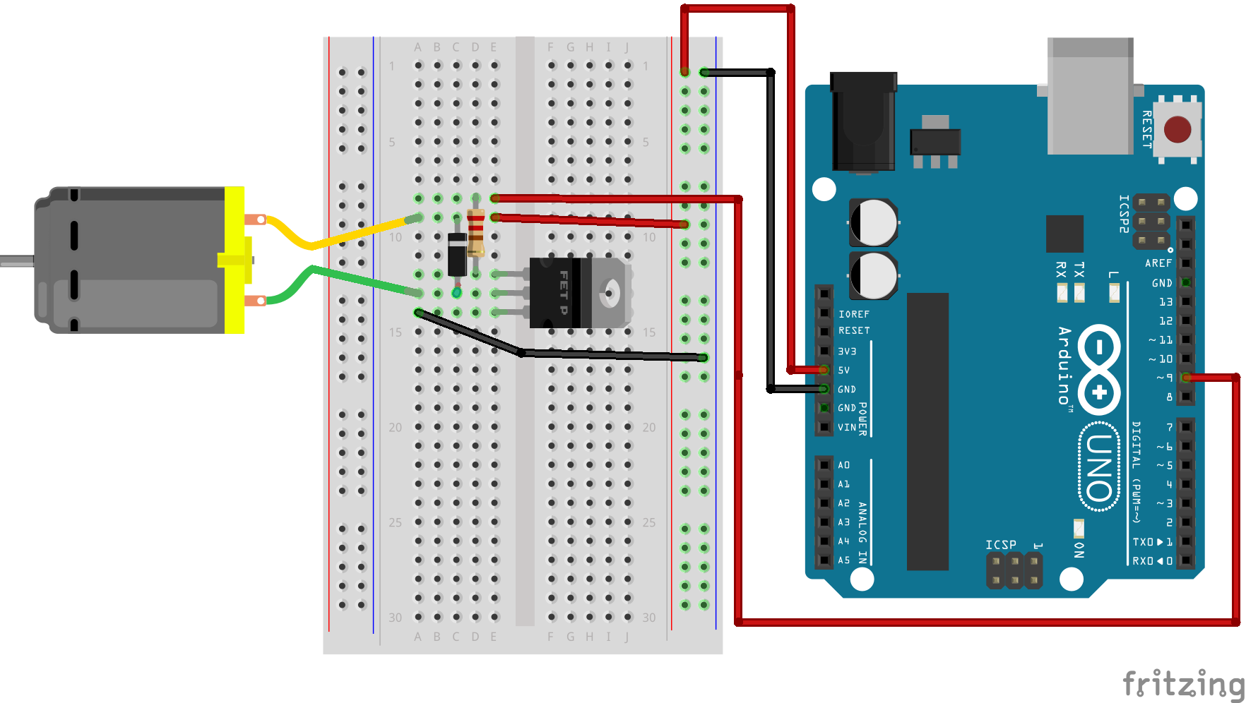
The Setup
- Connect 5v Power and Ground from your Arduino to your power and ground rails on your breadboard
- Insert your transistor on three separate lines of your breadboard, with the flat side facing outward.
- Connect your DC motor to separate lines on your breadboard, one to the 5v power line, the other to connect to the middle (collector) leg of the transistor.
- Connect your Diode between the two motor cables
- Connect a 220-ohm Resistor from the base (left) leg of the transistor to a separate line, then from that line to your digital IO pin.
- Connect the emitter (right) leg to the ground rail.
The Code
int motorControlPin = 9;                                                                   //Set pin 9 as motor control pin

void setup() {
  pinMode(motorControlPin, OUTPUT);                                                        //Set MotorControlPin as output Pin
  Serial.begin(9600);                                                                      //Start Serial Comms
  Serial.println("Enter a Value between 0-255 to set the speed of the motor");             //Let user know range of values to enter
}

void loop()
{
  if (Serial.available())                                                                   //If something is entered into the Serial Monitor
   {
    int speed = Serial.parseInt();                                                         //Take the first Integer entered and set the speed variable to the entered value
    analogWrite(motorControlPin, speed);                                                   //Write the 'speed' value to motorControlPin
   }
}
Upload the code to your board, if you want a more thorough understanding of the coding process read through the comments within the code.
Voila! Is nothing happening? Good! Open your serial monitor and follow the instructions. You should be able to set the motor speed in real time. Pretty neat right?
We used a power transistor to amplify the current for our motor control. Check out the Analog Electronics Crash Course put together by Sam if you want a quick rundown on the particulars of transistor operation. Sometimes we have bigger motors that require more current and voltage than our little Uno is able to deliver. We could try, but we would almost definitely fry something.
Our friends over at Adafruit have provided us with a wonderful solution in the form of an Arduino Motor Shield Kit. After some soldering, this shield provides the capability of controlling 4 DC motors at any time with 1.2A available per motor. The board also uses i²c communication to interface with our Arduino. If you want a quick refresher on I²C to check out our tutorial. We have also put together some introductory tutorials on using other types of motors:

